
Related Manuals for pyroscience Pico-O2


Summary of Contents for pyroscience Pico-O2
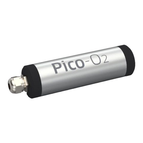
- Page 1 Pico-O OEM Fiber-Optic Oxygen Meter MANUAL PyroScience GmbH www.pyroscience.com...
- Page 2 Pico-O2 | Manual Pico-O OEM Fiber-Optic Oxygen Meter Document Version 1.08 The Pico-O2 is released by: PyroScience GmbH Kackertstr. 11 52072 Aachen Germany Phone +49 (0)241 5183 2210 +49 (0)241 5183 2299 Email info@pyroscience.com www.pyroscience.com Registered: Aachen HRB 17329, Germany...
-
Page 3: Table Of Contents
4.2 Using the software Pyro Developer Tool ................14 Option 3: Simplified Custom Integration ................15 5.1 Configuring the Module using PyroScience Software ........... 15 5.2 Electrical Connector for Custom Integration ..............15 5.3 Configuration of the Serial Interface ..................16 5.4 Communication Protocol ...................... - Page 4 Pico-O2 | Manual 5.4.8 #LOGO – Flash Status LED ................... 23 5.4.9 #PDWN – Power Down Sensor Circuits ..............23 5.4.10 #PWUP – Power Up Sensor Circuits ................ 24 5.4.11 #STOP – Enter Deep Sleep Mode ................24 5.4.12 #RSET – Reset Device ....................24 5.4.13 #RDUM –...
-
Page 5: Introduction
Pico-O2 | Manual INTRODUCTION Pico-O2 (item no. PICO-O2) is a fiber-optic OEM meter for read-out of optical oxygen sensors from PyroScience. The measures oxygen gas (e.g. %O2) or dissolved Pico-O2 oxygen in liquids (DO) and the firmware provides internal calculation of all major oxygen units taking into account adjustable values of temperature, pressure, humidity, and salinity. -
Page 6: Overview
OPROB3 is a fiber based optical sensor. The fiber has a length of 1 meter and is connected to the optical port of the Pico-O2. The dipping probe OPDIP20 is made out of stainless steel and has a length of 20 mm. Both probes have a diameter of 3 mm and are applicable in gas and liquid phase. -
Page 7: Contactless Sensor Spots
0-10 mm and PICROD3 for 10-20 mm. Figure 3: Connection of oxygen sensor spots to Pico-O2 via an optical fiber (left) or a rod (right). 2.1.3 Flow-through cells Oxygen flow-through cells (e.g. OXFLOW) can be connected via the optical fiber PICFIB2 to a Pico-O2. -
Page 8: Vials
Pico-O2 | Manual Figure 4: Connection of oxygen flow-through cell to Pico-O2 via an optical fiber. 2.1.4 Vials Oxygen vials (e.g. OXVIAL20) can be connected via the optical fiber PICFIB2 to a PICO- O2. To connect the optical fiber to the vial, an adapter (ADVIAL20T) is necessary. -
Page 9: External Temperature Sensor
First, remove the protective caps from both ends of the optical probe / fiber / rod. Then slightly unscrew and loosen the nut at the sensor port of the Pico-O2. The nut must not be removed from the sensor port. Typically, unscrewing the nut with a single half turn (180°) is sufficient. -
Page 10: Status Led
USB interface cable For the operation of Pico-O2 with a Windows PC, a coded USB interface cable (item no. PICO-USB) is available from PyroScience. It includes a license for the comfortable logger software and the software Tool. Especially for initial... -
Page 11: Option 1: Operating The Module With Pyro Workbench
Pico-O2 | Manual OPTION 1: OPERATING THE MODULE WITH PYRO WORKBENCH For initial evaluation purposes the module can be operated with the simple and customer-friendly software Pyro Workbench, which is typically used by end-users. This software offers comfortable settings and calibration wizards, as well as advanced logging features. -
Page 12: Using The Software Pyro Workbench
Pico-O2 | Manual • Start the Pyro Workbench software. Using the software Pyro Workbench Please refer to the Pyro Workbench manual for general operation instructions for the software (available on our website). Please refer to the Oxygen Sensor manual for general information on handling and calibration of the oxygen sensors (available on our website). -
Page 13: Option 2: Operating The Module With Pyro Developer Tool
Pico-O2 | Manual OPTION 2: OPERATING THE MODULE WITH PYRO DEVELOPER TOOL For advanced evaluation purposes the module can be operated with the software Pyro Developer Tool. It offers simple settings and calibration procedures, as well as basic logging features. Furthermore, additional advanced settings offer full control on all features of the module. -
Page 14: Using The Software Pyro Developer Tool
Pico-O2 | Manual • connect the USB plug to an USB port of the PC. The status LED of the Pico-O2 should flash shortly indicating the correct startup of the module. • Start the software. Pyro Developer Tool Using the software Pyro Developer Tool... -
Page 15: Option 3: Simplified Custom Integration
The module can then be integrated into a specific setup, and your custom software can perform measurements using a proprietary USB/UART communication protocol. Configuring the Module using PyroScience Software Please install either the Pyro Workbench... -
Page 16: Configuration Of The Serial Interface
Pico-O2 | Manual Figure 7: Electrical connectors of Pico-O2 The pin configuration of the connector X1 is given in Table 2 Table 2: Pin configuration of the connector X1 Name Function Description Power Power supply min. 3.3 VDC max. 5.0 VDC... - Page 17 Pico-O2 | Manual Note: The serial interface of this module is not an RS232 interface. However, the UART interface can be made compatible to RS232 by integrating an appropriate "level shifter electronics". © PyroScience GmbH...
-
Page 18: Communication Protocol
Pico-O2 | Manual Communication Protocol 5.4.1 General Definitions A command always starts with a specific command header (e.g. MEA, #VERS, #LOGO) optionally followed by several input parameters. Input parameters are given as human readable decimal numbers, separated by spaces from each other. Each command must be terminated by a carriage return. - Page 19 Pico-O2 | Manual Bit 5 (add 32): case temperature (temperature within the module) Example: S = 1 + 2 + 4 + 8 + 32 = 47 means, that the command will trigger the following measurements: optical channel (oxygen), sample temperature, case temperature, ambient air pressure, and relative humidity within the module housing.
- Page 20 Pico-O2 | Manual This command is the essential command for triggering measurements. If the input parameter S is requesting several sensor types to be measured, the optical oxygen measurement ("optical channel") is always performed as the last measurement. This ensures that for enabled automatic temperature compensation the sample temperature measurement (typ.
-
Page 21: Chi - Calibrate Oxygen Sensor At Ambient Air
Pico-O2 | Manual ambientLight = 11.788 mV percentO2 = 20.980 %O2 CHI – Calibrate oxygen Sensor at ambient air 5.4.3 This command is used for calibrating the upper calibration point of the oxygen sensor at ambient air. Command: CHI˽C˽T˽P˽H↵ Response: CHI˽C˽T˽P˽H↵... -
Page 22: Vers - Get Device Information
#VERS↵ Response: #VERS˽D˽N˽R˽S˽B˽F↵ Output Parameters: Device ID, identifies the specific device type. For the Pico-O2 the device ID is always 4. Number of optical channels. For the Pico-O2 this value is 1. Firmware version, e.g. R=403 designates firmware version 4.03... -
Page 23: Idnr - Get Unique Id Number
Pico-O2 | Manual Bit 3: analog out 4 Bit 8: user memory Bit 4: user interface (display, Bit 9-31: reserved buttons) Example: F = 1 + 2 + 4 + 8 + 256 = 271 means that 4 analog outputs are supported and the module possesses a user memory. -
Page 24: Pwup - Power Up Sensor Circuits
Pico-O2 | Manual command (e.g. MEA) requiring a sensor measurement. This is also the case if a broadcast measurement takes place. 5.4.10 #PWUP – Power Up Sensor Circuits This command switches on the power supply of the sensor circuits. Command: #PWUP↵... -
Page 25: Wrum - Write User Memory
Pico-O2 | Manual 2147483648 to 2147483647) which is located in the flash memory and is therefore retained even after power cycles. This read command returns N (N=1…64) consecutive values Y from the user memory starting at the user memory address R (R=0…63). - Page 26 Pico-O2 | Manual Note: Warnings and errors directly related to the sensor measurements (e.g. a broken Pt100 temperature sensor, or a "worn out" optical oxygen sensor) will not result in such an #ERRO response. Instead, such warning and errors are given in the output parameter of the MEA command (see above).
- Page 27 Pico-O2 | Manual Error Type Description General A non-specific error occurred. The requested optical channel does not exist. Channel Memory Access Memory access violation either caused by a not existing requested register, or by an out of range address of the requested value.
-
Page 28: Available Implementations Of Communication Protocol
Pico-O2 | Manual Available Implementations of Communication Protocol We offer libraries for controlling Pico-O2 using LabView programming language. The libraries and corresponding documentation are free for download from our website. © PyroScience GmbH... -
Page 29: Option 4: Advanced Custom Integration
Pico-O2 | Manual OPTION 4: ADVANCED CUSTOM INTEGRATION For advanced custom integration the full USB/UART communication protocol is available on request, allowing custom software full control on all settings, calibration and measurement features of the module. © PyroScience GmbH... -
Page 30: Technical Drawing
Pico-O2 | Manual TECHNICAL DRAWING The solder pads have 2.54mm pitch. © PyroScience GmbH... -
Page 31: Specifications
Pico-O2 | Manual SPECIFICATIONS General Specifications Dimensions L=59 mm, Ø 17mm (without the optical port) Weight ca. 20 g Power supply min. 3.3 VDC max. 5.0 VDC Connector plug Phoenix Contact PTSM0,5/4-P-2,5 Power consumption -during operation typ. 10 mA -during deep sleep mode typ. - Page 32 Pico-O2 | Manual Accuracy +-0.3 °C Range -40 to 125 °C © PyroScience GmbH...
-
Page 33: Safety Guidelines
Pico-O2 | Manual SAFETY GUIDELINES Before using the Pico-O2 and its sensors, read carefully the instructions and user manuals. In case of problems or damage, disconnect the instrument and mark it to prevent any further use. Consult PyroScience for advice. There are no serviceable parts inside the device. - Page 34 Pico-O2 | Manual CONTACT PyroScience GmbH Tel.: +49 (0)241 5183 2210 Kackertstr. 11 Fax: +49 (0)241 5183 2299 52072 Aachen info@pyroscience.com Deutschland www.pyroscience.com www.pyroscience.com...
Need help?
Do you have a question about the Pico-O2 and is the answer not in the manual?
Questions and answers