Table of Contents
Advertisement
Quick Links
Advertisement
Table of Contents

Related Manuals for pyroscience FireStingO2


Summary of Contents for pyroscience FireStingO2
- Page 1 FireStingO IBER OPTIC XYGEN ETER ANUAL...
- Page 2 Document Version 3.07 Refers to Pyro Oxygen Logger Software version >3.1 FireStingO2 is manufactured by PyroScience GmbH Hubertusstr. 35 52064 Aachen Germany Phone +49 (0)241 4004 555 +49 (0)241 4004 558 Email info@pyro-science.com Internet www.pyro-science.com Registered: Aachen HRB 17329, Germany...
-
Page 3: Table Of Contents
ABLE OF ONTENT OVERVIEW ................6 SAFETY GUIDELINES .............. 8 INTRODUCTION TO THE FIRESTINGO2 ........11 SOFTWARE INSTALLATION ........... 13 OXYGEN SENSOR TYPES............14 ............14 EEDLE ENSORS ..............17 IBER ENSORS ..............19 OBUST ROBES ................ 20 ENSOR POTS ............ - Page 4 7.1.6 Calibration Mode: Custom Mode ........61 O2 ....... 65 ALIBRATION WITH A ENERATION TING 7.2.1 Calibration Mode: Factory (1. Generation FireSting) .... 66 7.2.2 Calibration Mode: 1-Point (1. Generation FireSting) ..... 66 7.2.3 Calibration Mode: 2-Point (1. Generation FireSting) .... 69 7.2.4 Calibration Mode: Custom (1.
- Page 5 12.4 ............102 EASURING RINCIPLE 12.5 ......104 PERATING SEVERAL TING IN PARALLEL 12.6 ..........105 EFINITION OF XYGEN NITS 12.7 ..........107 ABLE OF XYGEN OLUBILITY 12.8 ........109 XPLANATION OF THE ENSOR...
-
Page 6: Overview
1 Overview The compact USB-powered fiber-optic oxygen meter FireStingO2 with 1, 2, or 4 channels unifies several innovative technological improvements making it the new standard of high precision oxygen sensing with fiber-optical oxygen sensors (optodes). The FireStingO2 utilizes measuring principle... - Page 7 OEM solutions. More information concerning our products can be found at www.pyro-science.com or contact us under info@pyro-science.com. We would be pleased to serve you concerning all needs for high precision oxygen sensing. Your PyroScience Team...
-
Page 8: Safety Guidelines
2 Safety Guidelines FireStingO2 is a laboratory instrument to be used with fiber- optic oxygen sensors (optodes) from PyroScience for measuring oxygen at high precision and resolution. In order to guarantee an optimal performance of the FireStingO2 please follow these operation instructions and safety guidelines. - Page 9 When used in the field, the environmental conditions (like high humidity, dust, exposure to direct solar radiation) may cause damage or interference of the FireStingO2, which is on the user's authority.
- Page 10 Before using the FireStingO2 and its sensors, read carefully the instructions and user manual for the oxygen meter FireStingO2. In case of problems or damage, disconnect the instrument and mark it to prevent any further use! Consult PyroScience advice! There are no serviceable parts inside the device. Please...
-
Page 11: Introduction To The Firestingo2
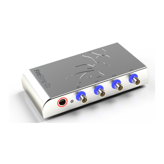
3 Introduction to the FireStingO2 FireStingO2 is an optical oxygen meter that is compatible with a broad range of oxygen sensors from PyroScience: microsensors and minisensors (retractable needle-type, fixed needle-type, or bare fiber), robust probes and contactless sensors (sensor spots, respiration vials, flow-... - Page 12 FireStingO2 comes with 1, 2, or 4 channels (connectors 1 to 4) on the right side panel for up to 4 fiber-optic oxygen sensors and one connector (T) for a temperature sensor. The Micro-USB connector on the left side panel provides the energy supply and the data exchange with the PC.
-
Page 13: Software Installation
4 Software Installation IMPORTANT: Do not connect the FireStingO2 to your PC before Pyro Oxygen Logger software has been installed. The software will install automatically the appropriate USB-drivers. System requirements: PC with Windows XP/Vista/7/8 (but not Windows RT) and min. -
Page 14: Oxygen Sensor Types
The needle-type oxygen sensors are composed of a fiber-optical cable (C) with an ST-plug (P) for connection to the FireStingO2 meter, a metal housing (H, fixed or retractable), and a syringe needle (N; 40 mm standard length) including the fiber with a fragile sensing tip and protected with a protective cap (PC). - Page 15 sensor tip of ca. 40-60 µm in diameter (A) and minisensors with a flat sensor tip of 230 µm or 430 µm (B), as well as fixed minisensors with 0.5 mm and 1.1 mm tip diameter (C). The retractable sensors are available as microsensors (OXR50; A) and as minisensors (OXR230, OXR430;...
- Page 16 Then the sensor should be fixed in a stable set-up like a solid laboratory stand or a micromanipulator mounted on a heavy stand from PyroScience. Move gently the push-button from the retracted position 0 to one of the extended positions 1-3. In position 1 the sensor tip is flush with the needle tip, whereby in positions 2 or 3 the fragile sensor tip extends ca.
-
Page 17: Bare Fiber Sensors
Please always use a stable stand and a micromanipulator to move the sensor into a semisolid sample like sediment, biofilm or soil. The minisensors are standard sensors for robust long-term oxygen measurements in gaseous or aquatic environments. Fixed minisensors with a mechanically protected tip (OXF500PT; C) can be used for insertion through a rubber septum without addition of air to gas samples. - Page 18 (P) to the oxygen meter FireStingO2. On each sensor, a label (L) with a specific Sensor Code is attached to the fiber-optic cable. The protective plastic tube (PT) covering the bare fiber has to be removed carefully before using the sensor. For this, fix the plastic tube in a stable laboratory stand, loosen the clamping screw and carefully pull out the bare fiber sensor.
-
Page 19: Robust Probes
5.3 Robust Probes Robust Oxygen Probes composed of a black fiber and a stainless steel tubing 3 mm in diameter, and 30 or 100 mm in length (e.g. item no. OXROB3, OXROB10). oxygen sensitive part is the disc 3mm in diameter located at the very end of the tubing (green disc in image below). -
Page 20: Sensor Spots
REDFLASH indicator with PET foil or glass as carrier material. The sensor spots allow oxygen measurements in closed vessels in combination with the FireStingO2 equipped with Optical Fibers (e.g. item no. SPFIB or SPFIB-CL2). The sensor spots have standard diameters of 5 mm (item no. OXSP5) and can be optionally obtained with an optical isolation (black coating) on the sensing surface (e.g. - Page 21 The spot adapter is then connected with the Optical Fiber (item no. SPFIB, SPFIB- BARE) to one channel of the FireStingO2.
-
Page 22: Flow-Through Cells
The flow-through cell can be directly connected with the Optical Fiber (item no. SPFIB or SPFIB-BARE) to the FireStingO2. CAUTION: For measurements in liquids, a flow rate of ca. 10-100 mL min is recommended for the OXFTC and of ca. 20-500 mL... -
Page 23: Respiration Vials
SPFIB-BARE SPFIB-BARE-CL2), which connects the respiration vial to one channel of the FireStingO2. The bare-fiber-versions of the optical fiber allow submersion in a water bath, as their fiber ends do not contain metallic parts potentially prone to corrosion. The position of the adapter rings (and the spot fiber) can be fixed by clamping screws. -
Page 24: Connecting The Sensors
The fiber-optic oxygen sensors, including needle-type and bare fiber micro- and minisensors, robust probes, as well as optical fibers needed for contactless sensors (sensor spots, flow-through cells, respiration vials) are connected to the ST-connectors of the FireStingO2 (1 to 4) with a male fiber plug. First, remove... -
Page 25: Cleaning And Maintenance Of The Sensors
5.8 Cleaning and Maintenance of the Sensors All oxygen sensors can be sterilized with ethylene oxide (EtO) and can be cleaned with peroxide (3% H2O2), soap solution or ethanol. They can be applied in gas phases, aqueous solutions, ethanol, methanol and isopropanol. Other organic solvents and gaseous chlorine (Cl2) induce interferences with the sensor reading. - Page 26 The bare fiber sensors need to be secured in the delivered plastic tube or in any customized housing to protect the fragile sensor tip. For the robust probes, put on carefully the small piece of plastic tubing onto the tip of the steel tubing to prevent any (destructive) impact on the sensor surface.
-
Page 27: The Software "Pyro Oxygen Logger
The four panels Channel 1-4 correspond to the channels 1-4 of the fiber-optic oxygen sensors connected to the FireStingO2. For the 1- or 2-channel version of the FireStingO2, only the respective panels will be visible. The default sensor readings show uncalibrated sensor readings (in raw value), which give only a qualitative information of the actual oxygen concentration. - Page 28 Note that placing the mouse on many elements of the window will show a short description (“tool tip”). By clicking on the right mouse button and selecting “Description and Tip” a more detailed description might be available additionally. After the activation of the respective channels in the Settings (see chapter 6.2), the sensor readings of each channel are displayed in...
- Page 29 A reasonable oxygen sensor shows signal intensities well above 20 (typically 50-500) . If the signal intensity drops below 50, this indicator bar turns gradually from grey to red indicating that the sensor might get degraded soon. Most sensors will still work even at a signal intensity of ca.
- Page 30 The unit of the x-axis can be changed with the selector Time Scale (using the arrows or clicking onto the field). The time scale can be displayed in Seconds (s), Minutes (min), Hours (h), Relative Time (HH:MM:SS), Absolute Time (HH:MM:SS), Absolute Time and Date and in Data Points.
- Page 31 button will allow inspection of older data which are not displayed anymore in the actual graph, e.g. during longtime measurements. The Plot Style of the charts can be changed by clicking with the right mouse button onto the black field of the respective color control (CC) above the chart recorder, opening a pop-up menu.
- Page 32 They can be reloaded anytime by pressing the button Load Setup. This allows e.g. to switch between different laboratory setups with a single FireStingO2. This function might be also useful if different computers are used for the calibration and for the actual measurements.
- Page 33 FireStingO2 meters. The different windows operate completely independent of each other and are assigned to exactly one FireStingO2. This allows measurements in different setups at the same time. The flashing of the logo (for ca. 1 sec after pressing the Flash Logo...
- Page 34 continuous sampling (default setting) or as continuous sampling limited to a defined time interval. The duration of the time interval can be adjusted in the duration display (DUD) shown as hour (HH): minutes (MM): seconds (SS). The Sample Interval (s) for continuous sampling can be defined in the field designed with set.
-
Page 35: Settings
Comment, the measurements can be commented and this comment is then saved together with the next data point into the data file. During data logging, the data file can be displayed and opened by clicking on the button Show File. The data saving is indicated by the light green arrow in the grey Log to File button and can be stopped by clicking this button again. - Page 36 Sensor Settings and (2) also the environmental Conditions in the Sample under investigation. Each oxygen channel of the FireStingO2 meter has its own tab in the FireSting Settings window. By clicking on Copy these Settings, all settings adjusted in the active channel tab can be pasted to all other channels.
-
Page 37: Basic Settings
NOTE: The Charts are automatically cleared in the panels of the Main Window after the Settings have been modified. Re- adjustments in the Settings might require also a recalibration of the sensor(s). If the changes of the Settings require a sensor recalibration, a warning Not Calibrated appears right-hand side of the Calibrate button in the corresponding channel panel of the Main Window. -
Page 38: Advanced Settings
6.2.2 Advanced Settings If Advanced Sensor Settings are chosen, more complex setting controls get visible. Please ensure that the correct sensor code attached to the sensor has been entered in the field Sensor Code. For robust probes (sensor type: X), the Fiber Length (m) of the connected robust probe must be entered. -
Page 39: Conditions In The Sample
Phase. Further, it needs to be selected if during the measurements the temperature will be determined by the External Temperature Sensor connected to the FireStingO2, by the Internal Temperature Sensor of the FireStingO2 (only possible for measurements in a Gas Phase!) - Page 40 PyroScience connected to the FireStingO2, and has to be adjusted manually. This Compensation Temperature, either entered manually at constant temperature conditions or measured by the external or internal temperature sensor of the FireStingO2, will be displayed in the corresponding channel panel of the main window (TD).
-
Page 41: Temperature
(e.g. mg/L or µM/L). 6.2.4 Temperature An External Temperature Sensor connected to the FireStingO2 and the Internal Temperature Sensor inside the FireStingO2 be activated in the panel Temperature. Both temperature sensors... - Page 42 (see also chapter 10). Alternatively, if the temperature extension module TeX4 is coupled to the FireStingO2, then automatic temperature compensation can be performed for each channel independently using the temperature sensor connected to the corresponding port of the TeX4.
-
Page 43: Options
In the panel Options, several internal sensors and an Analog In can be activated. The Internal Pressure Sensor and the Internal Humidity Sensor inside the FireStingO2 can be independently activated by clicking on the respective buttons and are displayed in the Overview panel (see chapter 0) of the main window and saved into the data file. - Page 44 Max. Data Points in Graphs (default: 10800). A change of the number will clear the graphs and high values (>>10000) might decrease the maximum sample rate. FireStingO2 offers four analog outputs (0-2.5V) at the extension port which can be configured by pressing the Analog Output button.
-
Page 45: Overview Panel
6.3 Overview Panel The sensor readings of all activated oxygen sensors (left y-axis), external and internal temperature sensors, internal pressure and humidity sensors (right y-axis) and signals from the Analog In (left y-axis) are displayed in the panel Overview. Each sensor reading is shown also as a numerical value in the chosen unit on top of the overview graph. -
Page 46: Raw Data Window
Ambient Light (in mV) gives a measure of the ambient light entering the sensor from outside. At too high ambient light levels the detector of the FireStingO2 might get saturated giving the warning Signal too high in this window and in the warning display... - Page 47 (Internal Temp. (°C)) in the FireStingO2 meter, the Pressure (mbar) and Humidity (%) measured by the internal sensors inside the FireStingO2, as well as the Analog In (mV) are also displayed. On the left side, the Status and different warnings can be...
-
Page 48: Calibration With "Pyro Oxygen Logger
“Pyro Oxygen Logger”. Please note that the possible calibration modes differ depending on the connected FireStingO2 device: If your device has integrated humidity and pressure sensors (e.g. FireStingO2 devices with micro-USB connector, firmware >3.0) proceed with chapter 7.1. -
Page 49: Calibration Procedure
7.1 Calibration Procedure Before starting the calibration, ensure that the correct Sensor Code has been entered in the settings (refer to chapter 6.2). To calibrate a sensor click on the button Calibrate in the corresponding channel panel. Note that during data logging this button cannot be used until Log to File was stopped. - Page 50 calibration in air saturated water or water-vapor saturated air for precise measurements around 100% air saturation. 2-Point in Ambient Air: taking the 0% and the air calibration value from a manual calibration for precise measurements over the full range (0-21% O2). This mode uses the ambient air for determining the air calibration value.
-
Page 51: Calibration Mode: Factory
Possible 0% Calibration Types in the Custom Mode: a manual 0% Calibration a Factory 0% Calibration. In the following the different calibration modes are described. 7.1.1 Calibration Mode: Factory NOTE: The Factory Calibration is intended only for rough measurements and testing purposes. -
Page 52: Calibration Mode: 1-Point In Ambient Air
If possible, position the oxygen sensor and the external temperature sensor (if used) close to the air holes at the backside of the FireStingO2. Ensure that the oxygen sensor and the external temperature sensor (if used) are completely dry; otherwise the relative humidity around the sensor will differ from the measured humidity inside the FireStingO2. - Page 53 go to the Settings, enter the correct Sensor Code and repeat the calibration. Then the air temperature needs to be determined. Either a Fixed Temperature is adjusted manually or the temperature is read from external temperature sensor selecting External Temperature Sensor. Wait now until the sensor reading is stable by observing the graph and the numerical display of the oxygen sensor reading.
-
Page 54: Calibration Mode: 1-Point In Water Or Humid Air
Note, that this calibration mode will automatically read the atmospheric pressure from the internal pressure sensor in the FireStingO2. The calibration standard with the air saturated water or water-vapor saturated air must be therefore exposed to the same atmospheric pressure (which is given in typical applications... - Page 55 Insert the oxygen sensor and the external temperature sensor (if used) into the flask containing the air-saturated water or water- vapor saturated air. Ensure that the correct sensor code has been entered in the Settings of the corresponding channel. If the sensor code displayed in the Factory 0% Calibration is not correct, click on Finish, go to the Settings, enter the correct Sensor Code and repeat the calibration.
-
Page 56: Calibration Mode: 2-Point In Ambient Air
Note, that this calibration mode will automatically read the atmospheric pressure and humidity from the internal pressure and humidity sensor in the FireStingO2. The temperature of the ambient air needs to be determined. Either, a Fixed Temperature is adjusted manually, or the temperature is read from the external... - Page 57 (if used) are completely dry; otherwise the relative humidity around the sensor will differ from the measured humidity inside the FireStingO2. It is recommended that the device and the sensor are placed for >10 min. under constant environmental conditions before the calibration is performed.
-
Page 58: Calibration Mode: 2-Point In Water Or Humid Air
Note that the button Set 0% will be highlighted as soon as the oxygen readings are within the expected range for the connected sensor type. If all readings have reached their steady state, click on Set 0%, and the actual oxygen sensor reading is taken for the 0% calibration. - Page 59 Note, that this calibration mode will automatically read the atmospheric pressure from the internal pressure sensor in the FireStingO2. The calibration standards must be therefore exposed to the same atmospheric pressure (which is given in typical applications For the air calibration point (Air with 100% Humidity or Air...
- Page 60 (°C). Note that the button Set Air will be highlighted as soon as the oxygen readings are within the expected range for the connected sensor type. If all readings have reached their steady state, click on Set Air, and the actual oxygen sensor reading is taken for the air calibration. If the oxygen reading seems to be out of the expected range, a warning will be shown offering the possibility to repeat the calibration.
-
Page 61: Calibration Mode: Custom Mode
NOTE: If using retractable needle-type sensors (e.g. OXR50, OXR230, OXR430), it is important that the sensor tip is extended to position 2 or 3 (see chapter 5.1) when the calibration value is taken. 7.1.6 Calibration Mode: Custom Mode The custom calibration mode is selected by clicking on the button Custom Mode. - Page 62 And for the 0% calibration the following types can be selected: Factory 0% Calibration (refer to chapter 0) 0% Calibration (refer to chapter 7.1.4) Most calibration types have been explained already in the preceding chapters (see references in the above list). Only the air calibration type Custom Calibration is a unique feature only available in the Custom Mode.
- Page 63 Internal Pressure Sensor can be selected alternatively. This option will read the ambient atmospheric pressure automatically from the integrated pressure sensor in the FireStingO2. The temperature of the calibration standard needs to be determined. Either, a Fixed Temperature is adjusted manually, or the temperature is read from the external temperature sensor by selecting External Temperature Sensor.
- Page 64 Consequently, calibration should performed. If the calibration type 0% Factory Calibration was selected no further steps are necessary (refer also to chapter 0). If 0% calibration was selected, follow the instructions given in chapter 7.1.4. Click on Finish for reverting to the main window.
-
Page 65: Calibration With A 1.Generation Firestingo2
7.2 Calibration with a 1.Generation FireStingO2 In case you are still working with a first generation FireStingO2 (Firmware ≥2.3) the dialog window FireSting Calibration shows the Calibration Modes Factory, 1-Point, 2-Point and Custom Mode: Three main modes of calibration can be chosen: Factory calibration (for a quick, rough calibration): taking the 0% and the air calibration values from the sensor code;... -
Page 66: Calibration Mode: Factory (1. Generation Firesting)
7.2.1 Calibration Mode: Factory (1. Generation FireSting) NOTE: The Factory Calibration (only for rough measurements and testing purposes) is only possible if the correct Sensor Code has been entered in the Settings (see chapter 6.2). If the calibration mode Factory Calibration is chosen, ensure that the correct sensor code has been entered in the Settings of the corresponding channel (as displayed in 2. - Page 67 The oxygen level in the calibration standard can be freely chosen in Oxygen (%O2). If the air calibration standard is based on ambient air or air saturated water, then this value should be kept at 20.95%O2 (default), representing the standard oxygen volume fraction in ambient air.
- Page 68 due to the actual weather conditions. Therefore, determining the actual atmospheric pressure with a barometer gives more precise results. The relative Humidity (%RH) of the gas phase (e.g. air) needs to be adjusted. If a calibration standard with water-vapor saturated air is used (see chapter 8.1.2), it must be adjusted to 100%RH.
-
Page 69: Calibration Mode: 2-Point (1. Generation Firesting)
For the Factory 0% Calibration, no further steps are necessary (refer also to chapter 7.2.1). Ensure that the correct sensor code has been entered in the Settings of the corresponding channel. 7.2.3 Calibration Mode: 2-Point (1. Generation FireSting) The calibration mode 2-point is selected by clicking on the button 2-Point. - Page 70 Wait for steady state until the sensor reading is stable by observing the graph. If External Temperature Sensor was selected, ensure also stable temperature readings indicated at Temperature Sensor (°C). Note that the button Set Air will be highlighted as soon as the oxygen readings are within the expected range for the connected sensor type (the latter does not apply for a custom air calibration with ≠20.95 %O2).
-
Page 71: Calibration Mode: Custom (1. Generation Firesting)
7.2.4 Calibration Mode: Custom (1. Generation FireSting) The custom calibration mode is selected by clicking on the button Custom Mode. This mode allows the user to combine freely all possible calibration types for the air calibration and the 0% calibration. The air calibration type can be selected by clicking on the “Air Calibration Selector”. -
Page 72: Advanced Adjustments
This section is only for advanced users! For very advanced applications it is possible to manipulate all internal calibration parameters of the FireStingO2 manually. This option is accessible by selecting Custom Mode and subsequently clicking on Advanced: Adjust Manually, which opens a separate window showing all internal calibration parameters. - Page 73 These parameters are specific constants for the REDFLASH indicators, and are automatically adjusted for the selected Sensor Type in the settings. Unless otherwise communicated by PyroScience, it is strongly advised to leave these parameters at their default values.
-
Page 74: Calibration Standards
8 Calibration Standards 8.1 The Air Calibration Standard The Air Calibration standard can be ambient air water-vapor saturated air air saturated water (100% air saturation) When inserting fragile needle-type oxygen sensors into the calibration standards, ensure that the sensor tips are not hitting against e.g. - Page 75 During the calibration of oxygen sensors, there are two possibilities to take the humidity into account: (1) The relative humidity and the temperature of the ambient air must be determined during the calibration. Pyro Oxygen Logger software calculates then automatically the real oxygen level under these conditions.
-
Page 76: Ambient Air
And in case of a second generation FireStingO2 (with micro USB connector), the built-in humidity and pressure sensors together with the internal or external temperature sensor will measure these parameters automatically for most calibration types (see also chapter 7). -
Page 77: Water-Vapor Saturated Air
Enclose wet cotton wool into a flask (e.g. DURAN flask) with a lid prepared with holes for the oxygen sensor and a temperature sensor from PyroScience. Typically about 1/3 to 1/2 of the flask volume is filled with the wet cotton wool, while the other volume fraction is left free for inserting the tip of the oxygen sensor, and optionally also the temperature sensor. -
Page 78: The 0% Standard
8.2 The 0% Standard The 0% calibration standard can be water mixed with a strong reductant water flushed with nitrogen gas (N nitrogen gas (N 8.2.1 Water Mixed with a Strong Reductant Fill an appropriate amount of water into a glass flask (e.g. Duran flask) with a lid prepared with holes for inserting the oxygen sensor and a temperature sensor. -
Page 79: Water Flushed With Nitrogen Gas
8.2.2 Water Flushed with Nitrogen Gas Fill water into a glass flask (e.g. Duran flask) with a lid prepared with holes for inserting the oxygen sensor and a temperature sensor. Close it and stream for about 10 minutes nitrogen gas through the water. -
Page 80: Calibration Of Contactless Sensors
(experienced by the FireStingO2). However, for typical applications around room temperature and below, a falsely determined relative humidity gives a maximum relative error of 1% for the air calibration (refer also to chapter 8.1). -
Page 81: Manual Background Compensation
FireStingO2 with the contactless oxygen sensor. Based on the Fiber Length (m) entered in the Settings (see chapters 6.2.1 and 6.2.2), a background signal for compensation is... - Page 82 one end of the Optical Fiber is connected to the corresponding channel of the FireStingO2 the other end of the Optical Fiber attached to the sensor spot (i.e. disconnect this end from the spot adapter, adapter ring or from the flow-through cell) Then wait for steady state and press the button Take Actual Values.
-
Page 83: Temperature Measurement
10 Temperature Measurement For the measuring range, precision and absolute accuracy of the internal and external temperature sensors refer to chapter 12.1. 10.1 Available External Temperature Sensors FireStingO2 provides one port for an external temperature sensor. PyroScience offers e.g. the dipping-probe temperature... -
Page 84: Automatic Temperature Compensation
4 temperature channels TeX4 has to be coupled to the FireStingO2. Then the automatic temperature compensation is performed individually using the temperature sensor connected to the corresponding port of the TeX4. - Page 85 However, it is also possible to use the automatic temperature compensation e.g. only for a single channel, whereas the other channels can be used for measurements at a Fixed Temperature. For the channels running at a fixed temperature, this temperature must be entered in the Conditions in the Sample in the Settings.
-
Page 86: Analog Output And Auto-Mode
FireStingO2 via the USB interface (as described in this manual). This user-friendly operation mode is generally recommended, as it offers easy control over the full functionality of the FireStingO2. However, several advanced features are available in addition for integrating the FireStingO2 in customized setups. - Page 87 FireStingO2 performs a new measurement (independent whether FireStingO2 is operated via a PC with the Pyro Oxygen Logger software, or if it is operated autonomously in the auto-mode). The analog output can be configured by opening the Settings window clicking...
- Page 88 voltage signals proportional to the measured value. The linear scaling of the voltage signal can be freely adjusted at 0 mV output corresponds to and 2500 mV output corresponds to. NOTE: Due to hardware restrictions, the very lower range of the analog output around 0-3 mV shows slight non-linearities.
-
Page 89: Auto-Mode
NOTE: Some older micro-USB-charger do not fulfill the new common standard for micro-USB-chargers. Such an old micro- USB-charger might not be recognized by the FireStingO2, and thus the auto-mode is not started. This can be checked by observing the flashing frequency of the logo. - Page 90 Here the Auto-Mode Sample Interval (s) can be adjusted, defining the time interval between consecutive measurements in the auto- mode. As an advanced feature, the option Enable Data Transmission activates digital data transmission via the UART interface of the extension port (details on request). NOTE: Only sensors (e.g.
-
Page 91: Advanced Auto-Mode
11.3 Advanced Auto-Mode NOTE: This section is only for advanced users! For advanced applications, the auto-mode can be configured even more flexible as described in the preceding chapter. First, it is possible to define an independent sample interval for each oxygen channel;... - Page 92 trigger signal was detected at the trigger input of the extension port (see appendix 12.2). By checking Enable Serial Port Data Transmission, the results for the respective channel are additionally transmitted via the UART interface of the extension port. Ref. Count is an advanced feature only relevant for high speed applications (details on request).
-
Page 93: Appendix
12 Appendix 12.1 Specifications of the FireStingO2 Dimensions 68 x 120 x 30 mm Weight 350 g Interface USB 2.0 Power Supply USB-powered (max 70mA at 5V) Supported operating systems Windows 2000, XP, VISTA, 7,8 (but not Windows RT) Operating temperature 0 to 50ºC... - Page 94 External Temperature Sensors* -30°C to 150°C, 0.02°C, 0.3°C Range, Resolution, Accuracy Internal Temperature Sensor* -40 to 125°C, 0.01°C, 0.3°C Range, Resolution, Accuracy Internal Pressure Sensor 300 to 1100 mbar, 0.06 mbar, typ. 3 mbar Range, Resolution, Accuracy Internal Humidity Sensor 0 to 100% rel.
-
Page 95: Extension Port X1
12.2 Extension Port X1 The extension port of the FireStingO2 consists of the two connectors X1 and X2 (fitting connector plugs can be obtained from Phoenix Contact item no. 1778887 and 1778861). 12.2.1 Connector X1 (Power, Digital Interface, Analog In) The pin configuration of the connector X1 is given in the table below. - Page 96 Name Function Description Power Ground Power Power supply, 3.5V to 5.0V DC max. 70 mA (typ 40 mA) /USB_DISABLE Disables USB interface Ground Digital Output Data transmission pin (0V or 3.3V) of the UART interface Digital Input Data receive pin of the (0V or 3.3V) UART interface (5V tolerant)
- Page 97 The following illustrations show typical use cases for the extension port X1: USB-Powered Auto-Mode FireStingO2 is powered e.g. by a USB connection to a PC. By closing the blue switch between pin 6 and pin 1, the auto-mode is activated. Note, if the...
- Page 98 1 and 2. The USB connector of the FireStingO2 is left unconnected. Note the additional connection between pin 1 and 3 powering down the internal USB interface of the FireStingO2. Full Control Mode via the UART Interface...
- Page 99 (OEM applications). Note the additional connection between pin 1 and 3 powering down the internal USB interface of the FireStingO2. Otherwise unintended data communication via a potentially still connected PC might disrupt the UART communication. More information is available on request.
-
Page 100: Connector X2 (Analog Output)
12.2.2 Connector X2 (Analog Output) The connector X2 provides 4 independent analog outputs with a range of 0-2.5V DC at a resolution of 14 bits (see table below). Refer to chapter 11.1 how to configure the analog outputs. Name Function Description Ground AO_A... -
Page 101: Troubleshooting
→ check whether the sensor cable is connected → increase Amplification in the Advanced settings → and/or increase LED Intensity in the Advanced settings → replace sensor, the tip might be broken/bleached Bad Reference Internal problem of the electronics → contact PyroScience... -
Page 102: Measuring Principle
12.4 Measuring Principle The new REDFLASH technology is based on the unique oxygen- sensitive REDFLASH indicator showing excellent brightness. The measuring principle is based on the quenching of the REDFLASH indicator luminescence caused by collision between oxygen molecules and the REDFLASH indicator immobilized on the sensor tip or surface. - Page 103 The measuring principle is based on a sinusoidally modulated red excitation light. This results in a phase-shifted sinusoidally modulated emission in the NIR. The FireStingO2 measures this phase shift (termed “dphi” in the software). The phase shift is then converted into oxygen units based on the Stern-Vollmer-Theory.
-
Page 104: Operating Several Firestingo2 In Parallel
70 mA); an external power supply for the USB-hub might be advisable. Pyro Oxygen Logger software has now to be started separately for each connected FireStingO2. So, if you want to operate e.g. 6 different FireStingO2 meters, you have to start the... -
Page 105: Definition Of Oxygen Units
Used in: gas and water phase For a calibrated sensor, the partial oxygen pressure p in units of hPa (equivalent to mbar) is the fundamental oxygen unit measured by the FirestingO2. partial pressure p Torr Definition: [Torr] = p [hPa] x 759.96 / 1013.25... - Page 106 with p100 = 0.2095 ( p – p (T) ) (T) = 6.112mbar x exp ( 17.62 T[°C] / (243.12 + T[°C])) : actual partial pressure : actual barometric pressure T: actual temperature (T): saturated water vapor pressure at temperature T Dissolved O2 concentration C µmol/L Definition:...
-
Page 107: Table Of Oxygen Solubility
12.7 Table of Oxygen Solubility The following Table shows the equilibrium oxygen concentration (T, P=1013mbar, S) in units of µmol/ L at standard atmospheric pressure of 1013 mbar as a function of water temperature in units of °C and salinity in units of PSU (“practical salinity unit” ≈ g/L). In order to correct these values for the actual atmospheric pressure , the following formula has to be applied: (T,P,S) = C... - Page 108 Temp (°C) (PSU) 456.6 398.9 352.6 314.9 283.9 257.9 235.9 217.0 200.4 450.4 393.6 348.1 311.1 280.6 255.0 233.3 214.7 198.3 444.2 388.5 343.7 307.3 277.3 252.1 230.8 212.4 196.3 438.1 383.3 339.4 303.6 274.0 249.3 228.3 210.2 194.3 432.1 378.3 335.1 299.9...
-
Page 109: Explanation Of The Sensor Code
12.8 Explanation of the Sensor Code The oxygen sensors are delivered with an attached sensor code which can be entered in the Settings (refer to chapter 6.2). The following figure gives a short explanation about the information given in the sensor code. XB7-532-205 Example Code: Sensor Type... - Page 110 LED Intensity 100% Amplification 200x 400x C0 (Factory Calibration at 0%O2) dphi0 = C0 / 10 C100 (Factory Calibration at 100%O2) dphi100 = C100 / 10 The values of the factory calibration are valid for the following calibration conditions: Partial Volume of Oxygen (%O2) 20.95 Temperature at both calibration points (°C) 20.0...
Need help?
Do you have a question about the FireStingO2 and is the answer not in the manual?
Questions and answers