
Related Manuals for pyroscience Pico-T


Summary of Contents for pyroscience Pico-T
- Page 1 Pico OEM Fiber-Optic Temperature Meter MANUAL Version V1.04 www.pyroscience.com...
- Page 2 Pico-T | Manual Pico OEM Fiber-Optic Temperature Meter Document Version 1.04 The Pico-T is released by: PyroScience GmbH Hubertusstrasse 35 52064 Aachen Germany Phone +49 (0)241 5183 2210 +49 (0)241 5183 2299 Email info@pyroscience.com www.pyroscience.com Registered: Aachen HRB 17329, Germany...
-
Page 3: Table Of Contents
4.2 Using the software Pyro Developer Tool ................12 Option 3: Simplified Custom Integration ................13 5.1 Configuring the Module using PyroScience Software ........... 13 5.2 Electrical Connector for Custom Integration ..............13 5.3 Configuration of the Serial Interface ..................14 5.4 Communication Protocol ...................... - Page 4 Pico-T | Manual 5.4.14 #ERRO – Response if Error Occurred ..............22 5.5 Available Implementations of Communication Protocol ..........24 Option 4: Advanced Custom Integration ................25 Technical Drawing ........................26 Specifications ..........................27 Safety Guidelines ......................... 29 © PyroScience GmbH...
-
Page 5: Introduction
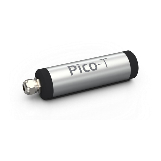
Pico-T | Manual INTRODUCTION The Pico-T (item no. PICO-T) is a fiber-optic OEM meter for read-out of optical temperature sensors from PyroScience. The Pico-T is characterized by its small size, durability and low power consumption. This OEM module is easy to integrate and is controlled with a simple serial communication protocol. -
Page 6: Overview
(item no. PICROD2 / PICROD3). To insert the optical fiber/rod, slightly loosen the nut at the sensor port of the Pico-T. Remove the protective cap from the optical fiber/rod and insert it carefully into the sensor port of the Pico-T until there is resistance. -
Page 7: External Temperature Sensor
External temperature sensor The optical temperature sensors need to be calibrated against an electrical Pt100 temperature sensor. For this, Pico-T offers a high-precision sensor interface, which can be directly connected to a Pt100 temperature sensor (not included, item no. TSUB21-NC). -
Page 8: Status Led
1-2 seconds. USB interface cable For the operation of Pico-T with a Windows PC, a coded USB interface cable (item no. PICO-USB) is available from PyroScience. It includes a license for the comfortable logger software Pyro Workbench and the software Pyro Developer Tool. Especially for initial testing purposes this software packages can speed up OEM-developments significantly. -
Page 9: Option 1: Operating The Module With Pyro Workbench
Pico-T | Manual OPTION 1: OPERATING THE MODULE WITH PYRO WORKBENCH For initial evaluation purposes the module can be operated with the simple and customer-friendly software Pyro Workbench, which is typically used by end-users. This software offers comfortable settings and calibration wizards, as well as advanced logging features. -
Page 10: Using The Software Pyro Workbench
USB interface cable to the connector X1 of the • Pico-T connect the USB plug to an USB port of the PC. The status LED of the Pico-T • should flash shortly indicating the correct startup of the module. -
Page 11: Option 2: Operating The Module With Pyro Developer Tool
Pico-T | Manual OPTION 2: OPERATING THE MODULE WITH PYRO DEVELOPER TOOL For advanced evaluation purposes the module can be operated with the software Pyro Developer Tool. It offers simple settings and calibration procedures, as well as basic logging features. Furthermore, additional advanced settings offer full control on all features of the module. -
Page 12: Using The Software Pyro Developer Tool
USB interface cable the connector X1 of the • Pico-T connect the USB plug to an USB port of the PC. The status LED of the Pico-T • should flash shortly indicating the correct startup of the module. -
Page 13: Option 3: Simplified Custom Integration
(or via the USB interface cable with its virtual COM port). Electrical Connector for Custom Integration The electrical interface of the Pico-T consists of the connector X1 (Figure 3). The package includes the fitting connector plug S1 (manufacturer: Phoenix Contact, type: PTSM0,5/4- P-2,5, Item no.: 1778858). -
Page 14: Configuration Of The Serial Interface
Ground Configuration of the Serial Interface Pico-T is operated via a serial interface, which is realized as a UART interface at 3.0 V levels (3.3 V and 5 V tolerant) consisting of a receive and a transmit line. The configuration of the UART-interface is as follows:... -
Page 15: Communication Protocol
Pico-T | Manual Note: The serial interface of this module is not an RS232 interface. However, the UART interface can be made compatible to RS232 by integrating an appropriate "level shifter electronics". Communication Protocol 5.4.1 General Definitions A command always starts with a specific command header (e.g. MEA, #VERS, #LOGO) optionally followed by several input parameters. -
Page 16: Mea - Trigger Measurement
Pico-T | Manual 5.4.2 MEA – Trigger Measurement This command triggers a measurement and returns the results. Command: MEA˽C˽S↵ Response: MEA˽C˽S˽R ˽R …R ↵ Input Parameters: Optical channel number. Set C=1. If in doubt, then set S to 47! This parameter defines the enabled sensor types,... - Page 17 Pico-T | Manual The results of the measurement given as 17 values. The most important 1… result values are highlighted. Name Unit Description dphi m° Phase shift of optical measurement (raw data) R2-R4 -reserved- tempSample 0.001 °C temperature (typ. external Pt100...
-
Page 18: Cot - Calibrate The Optical Temperature Sensor
Pico-T | Manual Example Communication: Command MEA˽1˽3↵ Response MEA˽1˽3˽0˽30120˽0˽0˽0˽27135˽0˽87016˽11788˽0˽0˽123022˽0˽27105 ˽0˽0˽0˽0↵ This example command triggers the measurement of the Pt100 temperature and of the optical temperature sensor. The highlighted output parameters of the shown example response are interpreted as follows: = 0 → No error or warning occurred; the measurement is valid! tempSample = 27.135 °C... -
Page 19: Vers - Get Device Information
#VERS↵ Response: #VERS˽D˽N˽R˽S˽B˽F↵ Output Parameters: Device ID, identifies the specific device type. For the Pico-T the device ID is always 4. Number of optical channels. For the Pico-T this value is 1. Firmware version, e.g. R=403 designates firmware version 4.03... -
Page 20: Idnr - Get Unique Id Number
Pico-T | Manual 5.4.6 #IDNR – Get Unique ID Number This command returns the unique identification number of the respective device. Command: #IDNR↵ Response: #IDNR˽N↵ Output Parameters: Unique ID number. Note, this parameter is given as an unsigned 64 bit... -
Page 21: Stop - Enter Deep Sleep Mode
Pico-T | Manual 5.4.10 #STOP – Enter Deep Sleep Mode This command puts the device into a deep sleep mode with very low power consumption Command: #STOP↵ Response: #STOP↵ During deep sleep mode the device has very low power consumption. No standard communication via USB/UART is possible. -
Page 22: Wrum - Write User Memory
This error response is mostly given, if the master did not send the command with the correct communication syntax. The output parameter C represents the general PyroScience error types as given by the following table. Note: Warnings and errors directly related to the sensor measurements (e.g. a broken Pt100 temperature sensor, or a "worn out"... - Page 23 Pico-T | Manual Error Type Description General A non-specific error occurred. Channel The requested optical channel does not exist. Memory Access Memory access violation either caused by a not existing requested register, or by an out of range address of the requested value.
-
Page 24: Available Implementations Of Communication Protocol
Pico-T | Manual Available Implementations of Communication Protocol We offer libraries for controlling Pico-T using LabView programming language. The libraries and corresponding documentation are free for download from our website. © PyroScience GmbH... -
Page 25: Option 4: Advanced Custom Integration
Pico-T | Manual OPTION 4: ADVANCED CUSTOM INTEGRATION For advanced custom integration the full USB/UART communication protocol is available on request, allowing custom software full control on all settings, calibration and measurement features of the module. © PyroScience GmbH... -
Page 26: Technical Drawing
Pico-T | Manual TECHNICAL DRAWING The solder pads have 2.54mm pitch. © PyroScience GmbH... -
Page 27: Specifications
Pico-T | Manual SPECIFICATIONS General Specifications Dimensions L=59 mm, Ø 17mm (without the optical port) Weight ca. 20 g Power supply min. 3.3 VDC max. 5.0 VDC Connector plug Phoenix Contact PTSM0,5/4-P-2,5 Power consumption -during operation typ. 10 mA -during deep sleep mode typ. - Page 28 Pico-T | Manual Internal Temperature Sensor (located on internal PCB) Resolution 0.02 °C Accuracy +-0.3 °C Range -40 to 125 °C Note: This max. sample rate refers only to the limits of the UART communication. It does not consider the actual response time of the connected optical temperature sensor or of the temperature sensor.
-
Page 29: Safety Guidelines
Please note that opening the housing will void the warranty. The Pico-T is not watertight. The Pico-T should be kept under dry and clean conditions, avoiding moisture, dust, corrosive conditions and excessive heating of the instrument (e.g. direct sun light). - Page 30 Pico-T | Manual CONTACT PyroScience GmbH Tel.: +49 (0)241 5183 2210 Hubertusstraße 35 Fax: +49 (0)241 5183 2299 52064 Aachen info@pyroscience.com Deutschland www.pyroscience.com www.pyroscience.com...
Need help?
Do you have a question about the Pico-T and is the answer not in the manual?
Questions and answers