Page 1
When using the instrument for the Troubleshooting first time 
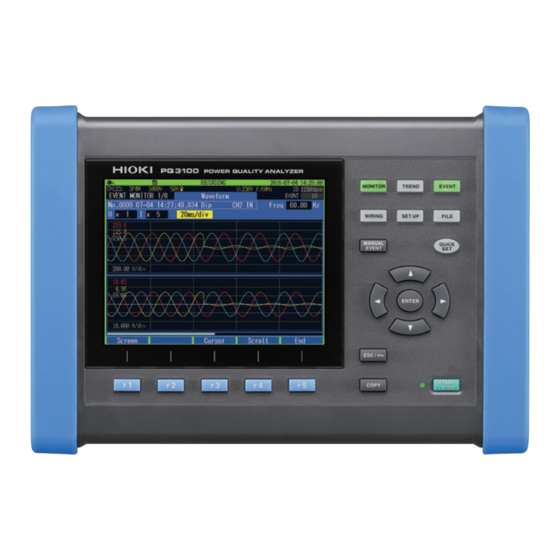
Names and Functions of Parts p.21 Maintenance and Service p.225 Preparing for Measurement p.35 Error Indication p.227 Dec. 2020 Revised edition 3 P Q3100A961-03 20-12H HIOKI PQ3100A961-03...
Attaching the strap (if required) ������������������39 System Settings ......75 Attaching the Z5020 Magnetic Strap System reset (Default) ��������������������������������76 (if required) �������������������������������������������������39 Factory reset (Default) ��������������������������������77 Setting the language, clock, and Factory settings ������������������������������������������78 measurement frequency �����������������������������40 PQ3100A961-03 HIOKI PQ3100A961-03...
Page 4
What can be done with the application IEC flicker meter and ΔV10 flicker meter ��104 software ����������������������������������������������������139 Verifying graphs and lists of IEC flicker Installation �������������������������������������������������140 (Pst, Plt) ����������������������������������������������������104 Verifying ΔV10 flicker graphs and lists ������106 HIOKI PQ3100A961-03...
Page 5
Appx. 8 Method for Calculating Active Power Accuracy . Appx.24 13.2 External Output ......175 Appx. 9 Terminology ....Appx.25 13.3 External Output Settings (SET UP Screen) ......176 13.4 Connection ........177 Index Ind.1 Specifications 14.1 General Specifications ....179 HIOKI PQ3100A961-03...
• The Bluetooth word mark and logos are registered trademarks owned by Bluetooth SIG, Inc. and any use of such marks by Hioki E.E. Corporation is under license. Other trademarks and trade names are those of their respective owners. •...
When you receive the instrument, inspect it carefully to ensure that no damage occurred during shipping. In particular, check the accessories, keys, switch, and connectors. If damage is evident, or if it fails to operate according to the specifications, contact your authorized Hioki distributor or reseller.
Page 9
Options The options listed below are available for the instrument. To order an option, please contact your authorized Hioki distributor or reseller. Options are subject to change. Please check Hioki’s website for the latest information. For current measurement CT7126 AC Current Sensor (60 A, φ15 mm) CT7131 AC Current Sensor (100 A, φ15 mm)
The effects of the magnetic force can cause abnormal operation of heart pacemakers and/or medical electronics. Indicates a prohibited action. Indicates the action which must be performed. MONITOR Names on the screen are displayed in bold characters. (Bold character) Operation keys are displayed in brackets Additional information is presented below. HIOKI PQ3100A961-03...
Page 11
The smallest displayable unit on a digital measuring instrument, i.e., the input value that causes the digital display to show a “1” as the least-significant digit. Protective gear WARNING This instrument measures live lines. To prevent electric shock, use appropriate protective insulation and adhere to applicable laws and regulations. HIOKI PQ3100A961-03...
Page 12
CAT IV: When measuring the circuit from the service drop to the service entrance, and to the power meter and primary overcurrent protection device (distribution panel). Distribution Panel Service Entrance Internal Wiring Service Drop CAT II CAT III CAT IV Outlet Power Meter Fixed Installation HIOKI PQ3100A961-03...
Preliminary Checks Before using the instrument, verify that it operates normally to ensure that no damage occurred during storage or shipping. If you find any damage, contact your authorized Hioki distributor or reseller. DANGER To prevent an electric shock, confirm that the white portion (insulation layer) inside the cable is not exposed.
Page 14
• Avoid contact between the cord and the measured line in order to protect the cord from damage. Any contact can cause the instrument to malfunction and lead to short-circuits or electric shock. HIOKI PQ3100A961-03...
Page 15
• When storing the instrument, make sure no objects that could short-circuit the connectors are placed near them. • For battery operation, use only the HIOKI Model Z1003 Battery Pack. We do not take any responsibility for accidents or damage related to the use of any other batteries.
Page 16
For example, even if the instrument determines that the card is not write-protected and allows data to be written to it, a computer may determine that it is write-protected, preventing data from being written to it. HIOKI PQ3100A961-03...
Page 17
• If the power does not turn on, the AC adapter or the instrument may be malfunctioning or the power cord may be disconnected. Contact your authorized Hioki distributor or reseller. • If an error during the self-test, the instrument is damaged. Contact your authorized Hioki distributor or reseller. Using Magnetic Adapter and Magnetic Strap...
Page 18
• Copying large data files from the SD memory card to a computer via the instrument’s USB interface can be time-consuming. When you need to copy a large data file to a computer, it is recommended to use an SD memory card reader. HIOKI PQ3100A961-03...
Page 19
• Keep discs inside a protective case and do not expose to direct sunlight, high temperature, or high humidity. • Hioki is not liable for any issues your computer system experiences in the course of using this disc. HIOKI PQ3100A961-03...
• Dedicated systems lines in the electrical substation (can be measured only by the power companies) • High-voltage and low-voltage lines of the service entrance • Distribution panels and switchboards • Power feeder and outlets of power supply for electric and electronic equipment HIOKI PQ3100A961-03...
If the EVENT indicator on the screen (p. 32) frequently changes to red, too many events have occurred. When the number of events reaches 9999 during recording/measurement, subsequent events will not be recorded (trend recording continues). Adjust the event settings as required. See “5 Setting Change (SET UP Screen)” (p. 63). HIOKI PQ3100A961-03...
Page 23
The Quick Set allows easy and secure procedure for setting and recording start by following the navigation of the instrument. The event settings also allows typical setting by only selecting the menu. (Menu: Voltage events, Inrush current, Trend record only, EN50160) See “3 Quick Set” (p. 45), supplied Measurement Guide. HIOKI PQ3100A961-03...
See “9 Checking Events (EVENT Screen)” (p. 111). Check for heat and unusual sounds. Motors, transformers, and wiring may produce heat or unusual sounds due to causes such as overloading or harmonics. HIOKI PQ3100A961-03...
See “3 Quick Set” (p. 45), Measurement Guide (provided separately). Data can be easily analyzed and reported. The data loaded to a computer can be easily analyzed and reported with the supplied software. See “11 Analysis (with Computer)” (p. 135) and “12 Communications (USB/LAN/RS-232C)” (p. 143). HIOKI PQ3100A961-03...
The instrument includes standard USB and Ethernet interfaces to connect a computer for the following operations. Communications • To configure the instrument using a computer. functionality • To download data from the instrument to the computer. • To operate the instrument remotely. See “12 Communications (USB/LAN/RS-232C)” (p. 143). HIOKI PQ3100A961-03...
Pressing and holding this key for at least 3 s activates the key lock function. (Same operation for unlock) Outputs the image of the currently displayed screen to the SD memory card. p. 127 Starts and stops recording. p. 93 HIOKI PQ3100A961-03...
Page 28
44 AC adapter connection jack Connects the AC adapter. p. 43 CHARGE LED Lights up when the Z1003 Battery Pack is charging. p. 38 Hook for AC adapter Loops the AC adapter cord through these hooks. p. 43 HIOKI PQ3100A961-03...
Page 29
The 9-digit serial number indicates the year (first two Serial No. digits) and the month of manufacture (next two digits). — Do not remove this sticker as the number is important. Installs the supplied Z1003 Battery Pack within the Battery compartment p. 38 compartment. HIOKI PQ3100A961-03...
Screen example: MONITOR screen The screens consist of seven screens each of which corresponds to the operation keys. The screen corresponding to the key pressed is displayed. The screen can be switched by pressing the key repeatedly. Screen name HIOKI PQ3100A961-03...
Phase relationship between voltage and current is displayed in a vector diagram. Harmonics screen Harmonic current, harmonic voltage, and harmonic power from 0 to 50th order are displayed. Zoom screen Enlarged view of 6 user-selected parameters are available. HIOKI PQ3100A961-03...
This screen is used to check trends of IEC flicker or ∆V10 flicker. Electric energy screen This screen is used to check electric energy trends for each recording interval. Demand screen This screen is used to check demand trends. HIOKI PQ3100A961-03...
See “4 Wiring (WIRING Screen)” (p. 47). Wiring settings screen Wiring check screen This screen is used to configure the wiring. This screen is used to check whether the Make wiring by checking the wiring diagram. instrument has been connected properly. HIOKI PQ3100A961-03...
System settings screen This screen is used to configure the clock, beep sound, language, display color, and phase name. Interface settings screen This screen is used to configure the settings for LAN, RS-232C, and external output. HIOKI PQ3100A961-03...
Minimum conditions required for recording can be set by following the Quick Set instructions. Quick Set start: [QUICK SET] See “3 Quick Set” (p. 45) and refer to Measurement Guide (provided separately). Quick Set start dialog Press the [ENTER] key. HIOKI PQ3100A961-03...
Move the cursor to the item. The drop down list will be displayed. Select an item. Accept the setting. On the MONITOR screen and the TREND screen, the items can be changed by pressing the keys without the drop-down list box displayed. HIOKI PQ3100A961-03...
Basic Key Operations Entering characters Move the cursor to the item. A dialog box will be displayed. Character selection Input Delete a character The setting will be accepted. Cancel The entry will be canceled. HIOKI PQ3100A961-03...
• During repeated recording, this screen is also displayed when recording is stopped. • The setting cannot be changed. Green (RECORDING): (START/STOP LED: On) • Recording is in progress. • The setting cannot be changed. HIOKI PQ3100A961-03...
Page 39
Indicates how much recording time or days remains on the SD memory card or in the instrument’s internal memory. If the event data is recorded – as well, the actual recording time will become shorter than the displayed recording time. The utilization status is indicated with a level meter. HIOKI PQ3100A961-03...
The voltage that the instrument is capable of measuring is being exceeded. Immediately disconnect the instrument. If the current is overrange, increase the current range. Measurement is not possible. Shown instead of the measured value. If there is no input, the power factor cannot be measured. HIOKI PQ3100A961-03...
• Setting the language, clock, and measurement frequency (p. 40) Pre-Measurement Inspection (p. 41) Inserting the SD Memory Card (p. 42) Power Supply (p. 43) Turning On the Instrument (p. 44) Warm-up (p. 44) • At least 30 min. HIOKI PQ3100A961-03...
Current sensor in use ×2 Black (thick) ×10 Model L1000-05 Voltage Cord ×3 Black (The model illustrated above is Model CT7136) Yellow CH1 Red CH1 Red N Black Black Yellow CH2 Yellow CH2 Yellow Yellow Model L1000-05 Voltage Cord Current sensor HIOKI PQ3100A961-03...
(Data that has been recorded on the SD memory card and instrument’s internal memory will be retained.) • For more information about the operating temperature and humidity and the storage temperature and humidity, see “14.1 General Specifications” (p. 179). HIOKI PQ3100A961-03...
Put the strap through the strap loop of the instrument. The magnetic force varies depending on thickness and unevenness of steel panels. Check for lack of the magnetic force so as not to let the instrument slip down. HIOKI PQ3100A961-03...
Once you have set the display language, time, and measurement frequency, this settings screen will not be shown again when the instrument is turned on. You can change these settings on the setting screen. See Display language, time “System Settings” (p. 75), and measurement frequency “SET UP, Measurement Settings 1 screen” (p. 64). HIOKI PQ3100A961-03...
Pre-measurement Inspection 2.3 Pre-measurement Inspection Before using the instrument, verify that it operates normally to ensure that no damage occurred during storage or shipping. If you find any damage, contact your authorized Hioki distributor or reseller. (1) Inspect the voltage cords...
How to remove: When storing the data to the SD memory card, configure the recording settings. Open the cover, push in the SD memory See “5.2 Recording Settings” (p. 69). card and then pull it out. HIOKI PQ3100A961-03...
Power Supply 2.5 Power Supply Be sure to read “Using AC Adapter” (p. 11). Required items Model Z1002 AC adapter (AC adapter + power cord) Power OFF Connect Hook AC adapter Connect Connect Power cord HIOKI PQ3100A961-03...
Slide the knob of the POWER switch toward OFF ( ). 2.7 Warm-up Warm up the instrument before performing the measurement to ensure accurate measurements. After turning on the instrument, allow it warm-up for at least 30 min. HIOKI PQ3100A961-03...
After this course is selected, event settings and recording interval will be automatically configured. Recording interval Configure the recording interval. Recording start method Configure the recording start method. Recording stop method Configure the recording stop method. Folder/File name Configure the folder/ file name. Clock Configure the clock. HIOKI PQ3100A961-03...
MONITOR screen. See “4.10 Checking Wiring” (p. 59). See “6 Verifying the Waveform, Measured Values (MONITOR Screen)” (p. 81). Press the [START/STOP] key. The recording will start. HIOKI PQ3100A961-03...
Attaching the current sensor to the measuring object “4.7 Attaching Current Sensors to Objects” (p. 56) Attaching Cords on a Wall (if required) “4.8 Attaching Cords on a Wall (if required)” (p. 57) Checking the wiring “4.10 Checking Wiring” (p. 59) HIOKI PQ3100A961-03...
PF/Q/S factor irrespective of calculation method settings of the SET UP, measurement settings 2 screen in the WIRING, wiring setting screen. See “SET UP, Measurement Settings 2 screen” (p. 66), Move the cursor Select and “Terminology” (p. Appx.25). HIOKI PQ3100A961-03...
Page 55
240, 277, 347, 380, 400, 415, 440, 480, The settings can also be configured in the SET UP, measurement settings screen or in the Quick Set screen. See “SET UP, Measurement Settings 1 screen” (p. 64), and refer to Measurement Guide. HIOKI PQ3100A961-03...
The wiring diagram shows the CH4 with ON state. Wiring Wiring selection selection Screens Screens vector vector diagram diagram 1P2W/DC – – 1P3W 1P3W1U 3P3W2M 3P3W3M* 3P4W 3P4W2.5E *: If 3P3W3M is selected, do not apply a voltage to CH4 even with CH4 set to ON. HIOKI PQ3100A961-03...
WIRING, wiring settings screen. the cord. Alligator Clip Magnetic Adapter Grabber Clip Insert the voltage cord while checking the channel on the screen. Voltage input terminal Insert the cord into the terminal as far as it will go. HIOKI PQ3100A961-03...
Current input terminal When disconnecting the current sensor, be sure to grip the part of the connector indicated by the arrows and pull it straight out. The current sensor and the maximum current range are set automatically. HIOKI PQ3100A961-03...
Clamp on Sensor Move the cursor Select *: Set the range switch of the sensor to 500 A Example: Select CT7136 for Model 9661 Clamp when the current range of this instrument is set on Sensor 500 A HIOKI PQ3100A961-03...
• In order to obtain precise measurements, zero adjustment should be performed at an ambient temperature level, that falls within the range defined by the device specifications. • The key operations are disabled during zero adjustment. HIOKI PQ3100A961-03...
Check the voltage values to verify that the connections have been Model 9804-01, -02 made securely. Magnetic Adapter * Optional, standard screws: M6 small pan head screws Model L1000-05 Voltage Cord HIOKI PQ3100A961-03...
Direction Arrow CT7044/ CT7045/ CT7046 AC flexible current sensor 「シールド線は挟まない」 の説明 記載する/しないは製品ごと技術 IMPORTANT ↓↓↓↓↓↓↓↓↓↓↓↓ Attach the clamp around only one line of the conductor. Single-phase (2-wire) or three-phase (3-wire, 4-wire) cables clamped together will not produce any reading. HIOKI PQ3100A961-03...
(steel). In particular, Model Z5004 can prevent the own weight of the voltage cords from detaching those alligator clips or magnet adapters. How to attach the strap “Attaching the Z5020 Magnetic Strap (if required)” (p. 39) HIOKI PQ3100A961-03...
If the range is too low, then an over-range current will be generated during measurement, and accurate measurement will not be possible. And if the range is too high, then errors will increase and accurate measurement will not be possible. HIOKI PQ3100A961-03...
*3: DPF (Displacement Power Factor) is displayed as the power factor irrespective of the PF/Q/S calculation SET UP, measurement settings 2 WIRING, wiring check method settings of the screen in the screen. See “SET UP, Measurement Settings 2 screen” (p. 66) and “Power factor (PF/DPF)” (p. Appx.29). HIOKI PQ3100A961-03...
Page 66
WIRING, wiring check confirmation screen. Recording can be started even if the wiring judgment result remains red (FAIL) or yellow (CHECK). Correct the wiring if the connections are incorrect. HIOKI PQ3100A961-03...
Page 67
• Does the arrow of the current sensor point to the load side? See “4.2 Wiring Method and Declared Input Voltage Settings” (p. 48). See “4.4 Connecting Current Sensors and Configuring Current Sensor Settings” (p. 52). See “4.7 Attaching Current Sensors to Objects” (p. 56). HIOKI PQ3100A961-03...
Page 68
Check the wiring and if no problems are observed, proceed with the measurement. See “4.4 Connecting Current Sensors and Configuring Current Sensor Settings” (p. 52). See “4.7 Attaching Current Sensors to Objects” (p. 56). HIOKI PQ3100A961-03...
In addition to the [SET UP] key, you can switch to the SET UP screen from here also. For the SET UP, Interface Settings screen, see “12 Communications (USB/LAN/RS-232C)” (p. 143) and “13 External I/O” (p. 173). HIOKI PQ3100A961-03...
See “SET UP, Event Settings 1 screen” (p. 72). Variable (50 V 800 V in 1 V increments), 100, 101, 110, 115, 120, 127, 200, 202, 208, 220, 230, 240, 277, 347, 380, 400, 415, 440, 480, The voltage range is fixed to 1000 V. HIOKI PQ3100A961-03...
Page 71
If the range is too low, then an over-range current will be generated during measurement, and accurate measurement will not be possible. And if the range is too high, then errors will increase and accurate measurement will not be possible. The present current value will be displayed. HIOKI PQ3100A961-03...
• Measurement of DC does not care that either 50 Hz or 60 Hz is configured. Enables you to sync source referenced for the measurement is fixed to U1. SET UP, Measurement Settings 2 screen [SET UP] SET UP, measurement settings 2 Press the key to display the screen. Move the cursor Select HIOKI PQ3100A961-03...
Page 73
A ∆V10 flicker meter used in Japan is applied. Enables you to select a weighting filter when Pst, Plt is selected for the type of flicker measurement. 230V lamp 230 V lamp system filter 120V lamp 120 V lamp system filter HIOKI PQ3100A961-03...
Page 74
: Move the cursor to the position of decimal point. Move the cursor : Change the location of the decimal point. When changing the value : Move the cursor to the digit that you wish to change. : Change the value. Accept the settings. HIOKI PQ3100A961-03...
All the parameters are recorded. Records the parameters other than the harmonic or interharmonic No harmonic parameters. Records the total harmonic distortion (THD). The display possible time of the TREND screen changes according to the setting of Recording interval Recording items. HIOKI PQ3100A961-03...
Page 76
Repeat The stop method cannot be changed for repeat recording. YYYY-MM-DD See “7.1 Start and Stop of the Recording” (p. 93). Displayed when Recording start setting is configured to Repeat. Set the recording period. hh:mm hh:mm HIOKI PQ3100A961-03...
Page 77
5 days 7 hours 2 sec 10 days 14 hours 10 sec 53 days 2 days 1 min 321 days 17 days 10 min 1 year 178 days 30 min 1 year 1 year … … … … HIOKI PQ3100A961-03...
1.0% 8.0% *1: The actual event threshold value is obtained by multiplying with the VT ratio. *2: The threshold value is set in terms of % of the declared voltage Uref (declared input voltage Udin × VT ratio). HIOKI PQ3100A961-03...
Page 79
Reference graph for setting threshold values You can adjust threshold values while viewing the present measured values. Threshold value upper limit Presently set threshold value Threshold value lower limit Present measured value HIOKI PQ3100A961-03...
If the before event or the after even set to exceeding 200 ms, only the waveform recorded during 200 ms can be observed with the instrument. To observe the entire length of the waveform, use the application software PQ One, which is supplied with the instrument. HIOKI PQ3100A961-03...
Italian Chinese Trad (Traditional) Spanish Korean Turkish Polish Enables you to select the display color. Color color color 3 Enables you to select the phase names for the measuring objects displayed on the wiring diagram. RST, ABC, L1L2L3, HIOKI PQ3100A961-03...
Perform if the instrument is operating in an odd or unexpected manner with no clear cause. Move the cursor All settings other than the measurement frequency, clock, language, and communication settings (LAN and RS-232C) are initialized to their factory settings. The internal memory will not be cleared. HIOKI PQ3100A961-03...
The factory reset will complete, and the language setting screen will be displayed. down the [ENTER] [ESC] keys, and continue holding them down until Set the language, clock, and measurement the beep sounds after the self-test is frequency (p. 40). complete. HIOKI PQ3100A961-03...
U, I, P: All levels Energy unit cost 0000.00/kWh Energy cost currency _____ Flicker – Filter Recording Recording interval 1min settings Recording items Yes harmonic Screen save Recording start method Interval time Recording stop method Manual Folder/ File name Automatic HIOKI PQ3100A961-03...
Page 86
From (Blank) Subject PQ3100 Mail settings 2 Mail authentication Server name (Blank) IP address 0.0.0.0 Port number Account name (Blank) Password (Blank) HIOKI PQ3100A961-03...
• If a setting is changed while measured values and waveform display are being held, the hold will be canceled. • The time display is not fixed. HIOKI PQ3100A961-03...
At the time of the cursor measurement: cursor measured values of the waveforms of each channel (Above diagram shows the screen that is displayed when the cursor is OFF) See “Verifying the measured value and time at the cursor position (cursor measurement)” (p. 83). HIOKI PQ3100A961-03...
Scrolling the waveform [F4] If the waveform is protruding from the screen, press the (Scroll) key to be able to scroll the waveform. Enables you to scroll the waveform in the vertical and horizontal directions by using the keys. HIOKI PQ3100A961-03...
(Line voltage) For 1P2W, 1P3W Fixed to Line-N For 3P3W2M Fixed to Line-Line For 3P3W3M, 3P4W, Can be switched between the Line-n and Line-Line. 3P4W2.5E Both the phase voltage and line voltage are stored as a output data. HIOKI PQ3100A961-03...
See Calculation method (p. 66). Active energy (WP+: consumption, WP-: regeneration) Reactive energy (WQ_LAG: lag, WQ_LEAD: lead) Energy cost Value obtained by multiplying the “active energy consumption: WP+” by the Unit cost* *: See “SET UP, Measurement Settings 2 screen” (p. 66) HIOKI PQ3100A961-03...
(Line voltage) For 1P2W, 1P3W Fixed to Line-N For 3P3W2M Fixed to Line-Line For 3P3W3M, 3P4W, Can be switched between the Line-Ne and Line-Line. 3P4W2.5E Both the phase voltage and line voltage are stored as a output data. HIOKI PQ3100A961-03...
Average value of the channels K factor See “Appx. 9 Terminology” Current zero-phase (p. Appx.25). unbalance factor (Not displayed for 3-phase 3-wire) See “Unbalance factor” (p. Appx.30). Current DC value Current negative-phase unbalance factor See “Unbalance factor” (p. Appx.30). HIOKI PQ3100A961-03...
Enables you to set the number of harmonic orders to be displayed. The values of the frequency, voltage negative-phase unbalance factor (Uunb), and current negative- phase unbalance factor (Iunb) remain the same as calculated by using the fundamental wave (1st order). HIOKI PQ3100A961-03...
Enables you to set at the time of Level display and % of FND display. Enables you to set the display method of the axes. Linear Linear display Logarithmic display (low levels also become easily visible.) Enables you to set the display of the interharmonics. HIOKI PQ3100A961-03...
Page 96
Set limits for 2nd to 25th order. 0.00% 100.00% Enables you to return to the MONITOR, Harmonics:graph screen. Enables you to recover the initial value (standard EN50160). Enables you to switch the maximum value (10% or 100%) for the vertical axis of the graph. HIOKI PQ3100A961-03...
Page 97
U1 are expressed in terms of 0° Phase Active power: The power factor of each harmonic order is expressed in terms of angle Enables you to set the display of the interharmonics. HIOKI PQ3100A961-03...
Move the cursor Select Item See “8.1 Verifying the Basic Trend”(p. 100), “8.5 Verifying the Electric Energy”(p. 108) Disable setting change. Only the total harmonic distortion (THD) harmonic parameter can be selected. All the other items can’t be selected. Item HIOKI PQ3100A961-03...
Time, Recording stop: Time WAITING RECORDING 2016/4/10 2016/4/12 8:00 18:00 Recording start Recording stop If the set time has already passed when the [START/STOP] key is pressed, the recording will be started at an appropriate time punctuation (Interval). HIOKI PQ3100A961-03...
Page 100
Recording stop Recording start Recording stop Present time Recording start 18:00 08:00 18:00 7:32 08:00 If the set time has already passed when the [START/STOP] key is pressed, the recording will start at an appropriate time punctuation (Interval). HIOKI PQ3100A961-03...
Page 101
• During repeated recording, this screen is also displayed when recording is stopped. • These settings can not be changed. Green (RECORDING): (START/STOP LED: On) • Recording is in progress. • These settings can not be changed. HIOKI PQ3100A961-03...
The fluctuation data that can be displayed on this instrument is limited. If the times listed in the following tables exceed, the old time series data is rewritten to the new time series data. Recording Yes harmonic Recording interval × 530 items No harmonic Recording interval × 10000 HIOKI PQ3100A961-03...
Use this key to scroll the graph in every direction. (If the zoom factor for horizontal axis [time axis] is set to Auto, the horizontal and vertical axes are automatically scaled so that the time series graph is entirely displayed on the screen. HIOKI PQ3100A961-03...
The waveform* or graph* at the time of event occurrence is displayed. *: The screen which displays initially varies according to the event items. • The recording start event generates when the recording starts and recording stop event generates when the recording stops. HIOKI PQ3100A961-03...
(The figure on the left illustrates the screen that is displayed when the cursor is disabled.) Move the cursor Select HIOKI PQ3100A961-03...
Page 107
Set the zoom factor for the vertical axis of the graph. Auto, ×1, ×2, ×5, ×10, ×25, ×50 Set the zoom factor for the horizontal axis (time axis) of the graph. The horizontal axis (time axis) which can be set, differs according to the recording intervals. HIOKI PQ3100A961-03...
The average value during the recording interval is displayed. The minimum value during the recording interval is displayed. Enables you to set the number of harmonic orders to be displayed. User-specified Set any orders from 0th (DC component) to 50th order. Not displayed. HIOKI PQ3100A961-03...
• The first and second measured values immediately after flicker type setting may be larger than the actual values due to the effect of High-pass filter used in the instrument. It is recommended to start recording approx. 5 min. after the flicker type setting. TREND,Flicker:graph screen Move the cursor Select HIOKI PQ3100A961-03...
Page 111
• The EN50160 “Voltage characteristics of electricity supplied by public distribution systems” gives a limit as “Plt≤1 for 95% of period within a week”. • Verify the Plt supporting the standard every 2 hours after 2 hours or more has lapsed from the start of measurement. HIOKI PQ3100A961-03...
Set the zoom factor for the vertical axis of the graph. Auto, ×1, ×2, ×5, ×10, ×25, ×50 Set the zoom factor for the horizontal axis (time axis) of the graph. Auto, 1min/div, 2min/div, 5min/div, 10min/div, 30min/div, 1hour/div, 2hour/div, 6hour/div, 12hour/div, 1day/div HIOKI PQ3100A961-03...
Page 113
1 min. The ∆V10 flicker limits used in Japan are 0.32 V for the average value (average hourly value), and 0.45 V for the maximum value (maximum hourly value, 4th maximum hourly value, or total maximum value). HIOKI PQ3100A961-03...
Set the zoom factor for the vertical axis of the graph. Auto, ×1, ×2, ×5, ×10, ×25, ×50 Set the zoom factor for the horizontal axis (time axis) of the graph. The horizontal axis (time axis) which can be set, differs according to the recording intervals. HIOKI PQ3100A961-03...
Enables you to set the display parameters. Dem_P+ Active power demand value (Consumption) Dem_P- Active power demand value (Regeneration) Dem_Q_LAG Reactive power demand value (Lag) Dem_Q_LEAD Reactive power demand value (Lead) Dem_S Apparent power demand value Dem_PF Power factor demand value HIOKI PQ3100A961-03...
Page 116
Verifying the Electric Energy HIOKI PQ3100A961-03...
• When making measurements using events, ensure that event settings has been enabled by using the Event Setting screen in SET UP mode. • Up to 9999 events can be displayed. Depending on the repeated recording setting, events for up to 9999 × days (up to one year) can be recorded. HIOKI PQ3100A961-03...
Page 118
*2: Saved only for event IN. If a number of event IN occur continuously, no event trend data may be present. *3: If swell event or dip event occurs after RVC event IN or before RVC event OUT, the RVC event is discarded and becomes swell event or dip event. HIOKI PQ3100A961-03...
RVC event IN. For frequency events, the list indicates up (when the reading is greater than the threshold value). DOWN For frequency events, the list indicates down (when the reading is less than the threshold value). Date Date of event HIOKI PQ3100A961-03...
Cursor position can be changed for each page. [F5] (Latest Event) key: Switch event item You can move the cursor to the latest event. An SD card is required to be inserted to refresh the displayed details HIOKI PQ3100A961-03...
The value less than 1 ms of the time shown in the event list is discarded. The value less than 1 ms used for cursor time (waveforms) is rounded off, possibly leading to the difference of 1 ms between the event list time and cursor time. HIOKI PQ3100A961-03...
(p. 92)* Harmonics screen (p. 89)* Enlarged view of 6 user-selected items are Harmonic voltage, harmonic current, and harmonic available. power from 0 to 50th order are displayed. *: Data for every 200 ms on an event is displayed. HIOKI PQ3100A961-03...
• Event trend data is displayed only for swell, dip, interruption, RVC, or inrush current event IN. • Even if another event occurred during event trend data recording (30 s), the event trend data for the event will not be saved. HIOKI PQ3100A961-03...
• Transient waveforms are only displayed for transient voltage events. • The transient waveform displays data sampled at 200 kS/s. Since event waveforms display data reduced to 12.5 kS/s, the effect from a transient waveform may not be reflected to the event waveforms. HIOKI PQ3100A961-03...
Worst value of the day from the start of repeated recording to present for the event parameter at the cursor position (Only when Recording start is configured to Repeat (p. 70).) CH4 transients are included in the statistics for CH123. HIOKI PQ3100A961-03...
SD memory card, as described below: • The instrument was unable to save data because the SD memory card was full. • The SD memory card was changed. HIOKI PQ3100A961-03...
10.1 Viewing and Using FILE Mode Screen Press the [FILE] key to display the FILE screen. FILE, SD card screen Folder hierarchy Occupied memory size SD memory card size FILE, Internal memory screen Occupied memory size Internal memory size HIOKI PQ3100A961-03...
Page 129
SD memory card to the computer (p. 137). FILE, Internal memory screen Copies data selected from the internal memory to the SD memory card (p. 131). (Copy) Deletes selected folders/files (p. 131). (Delete) Formats the SD memory card or the internal memory (p. 132). (Format) HIOKI PQ3100A961-03...
SD memory card. If the PQ3100 base folder does not exist on the SD memory card, it will be created automatically when a file is created. SD memory card root PQ3100 Screen copy base folder folder PQ3100 HARDCOPY Settings folder SETTING HIOKI PQ3100A961-03...
Page 131
IT000.ITV † If the file size exceeds 100 MB (20 MB, when automatic … FTP data transmission is enabled) or the SD memory card is inserted or ejected, the file is divided. FL000.FLC (Up to 1000 files) … HIOKI PQ3100A961-03...
Folders for measured data* (Random folder/ File name) HIOKI00.SET HIOKI00 IT000.ITV 00: Sequential number (00 to … HIOKI01 For repeat recording, folders are created for each day. *: When 64 files are created, no further recording is available. HIOKI PQ3100A961-03...
Move to one of the following. Select screen copy data (.BMP). Navigate within Load Select Select hierarchy folder HARDCOPY • folder under the AUTOCOPY • measurement data folder Image file name The image is displayed. Pressing the [ESC] key will close the image. HIOKI PQ3100A961-03...
Save the setting file. The setting file will be saved. Save to folder On the FILE, SD card screen: /PQ3100/SETTING On the FILE, Internal memory screen: /SETTING Save FILE, SD card Sample screen: screen HIOKI PQ3100A961-03...
Select a settings file (.SET) to load. Navigate within Load Select hierarchy SD memory card: The setting file will be loaded to the instrument. /PQ3100/SETTING Internal memory: /SETTING The measured data save folder also has the setting file used during the measurement. HIOKI PQ3100A961-03...
SD card screen or FILE, Internal memory from it. screen. appears on the screen) Select the folder or file to delete. The folders or the files will be deleted. Select Delete Sample screen: FILE, SD card screen HIOKI PQ3100A961-03...
• Be sure to use the instrument to format SD memory cards. The instrument can only save data to SD memory cards that have been initialized with the dedicated SD format (The format of Hioki’s optional SD memory cards is dedicated SD format).
SD memory card (the data will be divided and saved as a new file). • Files that are backed up to the internal memory are not transferred by the FTP client function. HIOKI PQ3100A961-03...
Page 140
Removing SD Memory Card during Recording HIOKI PQ3100A961-03...
USB cable Copy the data from the internal memory to the SD memory — p. 131 card and copy the data from the SD memory card : Supported, —: Not supported HIOKI PQ3100A961-03...
Explorer. Click This PC, and then, double-click Copy the necessary folders to the any PQ3100SD. folder on the computer. If the SD memory card was not formatted with Removable Disk the instrument, then will be displayed. HIOKI PQ3100A961-03...
• Attach the clamp as close as possible to the connector of the computer. • Make more than one turn cable around the clamp (5 turns are more effective). Ferrite clamp (commercially available) The ferrite clamp (segmented core) shown in the figure is the product of NEC Tokin. (Model: ESD-SR-250) HIOKI PQ3100A961-03...
Page 144
To disconnect a USB cable connected to the instrument from a computer which is ON: Press the [ESC] key to terminate the Disconnect the USB cable from the USB connection. computer. Alternately, eject the disk by using the [Safely Remove Hardware and Eject Media] icon on the computer. HIOKI PQ3100A961-03...
Displays lists of file information including settings and the number of events Dragging a folder containing measurement data displays lists of all data and event occurrences included in the folder. Refer to the Application Software Instruction Manual (CD) for details. HIOKI PQ3100A961-03...
The Adobe Reader must be installed on your computer to view the Instruction Manual. (Adobe Reader can be downloaded from the Adobe website.) To request a paper copy of the user manual, contact an authorized Hioki distributor or reseller. You can purchase the manuals.
Page 147
PC, and then, double-click File Explorer to start Explorer DVD RW Drive. Double-click the English folder. Double-click setup.exe (SET UP file). (The extension may not be displayed.) After the installer starts, follow the instruction to proceed with the installation. HIOKI PQ3100A961-03...
Page 148
Use of Application Software PQ One (Included) HIOKI PQ3100A961-03...
165 time. (E-mail transmission function) Configuration of the settings, Contact your authorized acquiring the measurement data, Hioki distributor or reseller and downloading the data from the — for more information about computer voluntarily, can be done by communications commands using communication command.
(IT department) has to assign the settings beforehand. The settings must not overlap with another device. Obtain assignments from the administrator (IT department) for the following items, and write them down. IP address Subnet mask Default gateway HIOKI PQ3100A961-03...
Page 152
Example: When building the network using network addresses 192.168.1.0/24 (192.168.0.1 to 192.168.1.255) IP address Computer : 192.168.1.1 Instrument : 192.168.1.2 (Set to a different IP address than the computer.) Subnet mask 255.255.255.0 Default gateway Computer : Instrument : 0.0.0.0 HIOKI PQ3100A961-03...
(Model 9642 accessory). Verifying the Transmission and Reception The RX/TX LED blinks during the transmission or reception of data. The LINK LED lights up, when the communication with the connected device is possible. LINK LED RX/TX LED HIOKI PQ3100A961-03...
Page 154
Preparing for LAN Communications Example of Remote Control Using Wireless LAN Computer Wireless LAN router Tablet computer HIOKI PQ3100A961-03...
• Set the browser security level to “Medium” or “Medium-high.” Or enable the active scripting settings. • Remote control can be performed even if the instrument’s key lock is active. HIOKI PQ3100A961-03...
If no password has been set or the password has been set to “0000” (four zeros), this screen will not be displayed. The default password is “0000.” The same screen and control panel being displayed on the instrument will be displayed on the browser. HIOKI PQ3100A961-03...
If you forget your password Perform “Factory reset (Default)” (p. 77) on the instrument to reset the password to its default figures of “0000.” The password cannot be initialized by remote control. HIOKI PQ3100A961-03...
The FTP server of this instrument is set to anonymous authentication, thereby allowing all devices on the network to access to the instrument when Authentication is set to disable. Config FTP To complete the settings: Press the [F1] (Return) key. HIOKI PQ3100A961-03...
Page 159
Enable when trying to restrict connection to the FTP server. Configure a user name used when connecting an FTP client to the instrument. (Up to 20 one-byte characters, example: HIOKI) Configure a password used when connecting an FTP client to the instrument.
• Previous data excluding the latest one may end up getting downloaded to the computer (as data left from the previous access gets saved as temporary Internet files in web browsers). When wanting to perform remote control: See “12.2 Remote Control of the Instrument through the Internet Browser (LAN Communications Only)” (p. 149) HIOKI PQ3100A961-03...
• To automatically send data using an FTP client, you must specify the IP address of the computer on which the FTP server is operating. • You can use such FTP server software as Windows FTP server (IIS) and FILEZILLA Server (free software). HIOKI PQ3100A961-03...
Turn Windows features on or off. Check FTP Service IIS Management The FTP will be installed to the computer. After the installation, inetpub folder will be Console and then click OK. created under the root of the drive C. HIOKI PQ3100A961-03...
Page 163
Set as follows and then click Next. Next. IP Address All unassigned FTP site name (example) Port Content Specify a directory to Directory which data will be saved Start FTP site Check from the FTP client. automatically No SSL HIOKI PQ3100A961-03...
Page 164
Advanced Settings. Click Inbound Rules and then right click FTP Server (FTP Traffic-In) to Properties. 1. Click 2. Right click 3. Click Communication may be blocked depending on the configuration of the software protecting the computer (e.g. firewall). HIOKI PQ3100A961-03...
Page 165
Automatically Sending Data Being Recorded to the Computer Check Enabled FTP Server (FTP Check that FTP Server (FTP Traffic-In) Traffic-In) and then click OK. is enabled (checked) and then close the dialog. HIOKI PQ3100A961-03...
Page 166
- Right click Users and then click User. 1. Right click 2. Click Set as follows and then click Create. User name HIOKI Full name HIOKI Password Enter your password Confirm password Re-enter your password Password never Check expires HIOKI PQ3100A961-03...
Page 167
Automatically Sending Data Being Recorded to the Computer Check that HIOKI has been registered as a user and then close the dialog. (5) Access permission configuration for FTP folders Open “C:\inetpub” and then click On the Security tab, click Users Properties for ftproot.
_._._._ (“_”: must be between 0 and 255), (e.g. 192.168.1.10) Set a user name needed to log in to the FTP server. Use the user name of the instrument registered to the FTP server of the computer (p. 160). (Up to 20 one-byte characters, example: HIOKI) HIOKI PQ3100A961-03...
SET UP, Interface settings screen. Display the Interface : FTP screen. Conduct a connection test. Select Execute Config FTP Upon error, check “Setting FTP Server of the Computer” (p. 156) and “Configuring the instrument (SET UP screen)” (p. 162). HIOKI PQ3100A961-03...
When wanting to perform remote control: See “12.2 Remote Control of the Instrument through the Internet Browser (LAN Communications Only)” (p. 149) HIOKI PQ3100A961-03...
Select Press the [SET UP] key to display the SET UP, Interface settings screen. Display the Interface: Email 1 screen for configuration. c o n f i g u r a t i o n . Config mail HIOKI PQ3100A961-03...
Page 172
Enter a port number for the mail server if it is other than the standard number (25). 65535 Enter a sender’s e-mail address. (Up to 32 one-byte characters), Example: pqa@xyz.xx.xx Enter a sender’s name. (Up to 50 one-byte characters), (e.g. HIOKI) Enter the subject of the e-mail. (Up to 20 one-byte characters) HIOKI PQ3100A961-03...
Page 173
Whether to set the server name or the IP address depends on the DHCP and DNS setting (p. 144). Server name: Up to 32 one-byte characters address: _._._._ (“_”: must be between 0 and 255) (POP authorization only) Set a port number for the POP3 server. 65535 HIOKI PQ3100A961-03...
If a test e-mail does not reach the destination specified, check the setting. The transmission test results will be saved to the log file in the PQ3100 basic folder (MAIL_LOG.TXT). Time required for e-mail transmission It takes approximately 1 second to send an e-mail. HIOKI PQ3100A961-03...
2016-11-29 16:14:42.2 EVENT No.0005 Uthd CH 1 OUT Level: 3.84 % Worst: 21.10 % Duration: 000:00:12.028 When wanting to perform remote control: See “12.2 Remote Control of the Instrument through the Internet Browser (LAN Communications Only)” (p. 149) HIOKI PQ3100A961-03...
19200 bps, 38400 bps Move the cursor Select Connection Connect the instrument and computer Turn on the computer. with the Model 9637 RS-232C Cable (cross cable). Model 9637 RS-232C Cable (Optional) Turn on the instrument. (p. 44) HIOKI PQ3100A961-03...
LR8410 Link Compatible Logger Communication Preparations 12.7 LR8410 Link Compatible Logger Communication Preparations When the instrument is connected to Hioki LR8410 Link compatible logger (LR8410, LR8416 ® ) with Bluetooth , measured values (6 parameters selected on the Zoom-in [available only in Japan] screen) of the instrument can be sent to the logger.
Prohibited for the adapter appears. character Press the [MONITOR] key to display the For detailed settings for Hioki LR8410 Link compatible logger (LR8410, LR8416 [available MONITOR, Zoom screen for parameter only in Japan]), refer to the Instruction Manual of selection.
When you connect the external output terminal there is an anomaly operation. to a trigger input terminal on a waveform recording device such as the Hioki Memory See “13.1 Event Input” (p. 174). HiCorder, you can record waveforms on the Memory HiCorder when an abnormality occurs.
• Longer wires may cause malfunction due to external noise. Wind the wires around a ferrite clamp as shown in the figure before connection (position the ferrite clamp as near the terminal block as possible). HIOKI PQ3100A961-03...
Isolated with a photo current coupler Active Low Maximum input 30 V Output format Short pulse setting: Approx. 10 ms voltage pulse output Long pulse setting: Approx. 2.5 s pulse output ΔV10 alarm setting: Low level during alarm HIOKI PQ3100A961-03...
This setting can be selected only when the flicker setting is ∆V10 (p. 66). ∆V10 alarm If the ∆V10 alarm is set, also set the threshold value (0.00 V 9.99 Output will be set to low when the set threshold value is exceeded. HIOKI PQ3100A961-03...
While the button is pressed, insert the wire into the electric wire connection hole. Press the button. The electric wire is locked in place. Turn on the external device. Turn on the instrument. (p. 44) HIOKI PQ3100A961-03...
Display 6.5-inch TFT color LCD (640 × 480 dots) Interface SD memory card, USB, LAN, RS-232C, external I/O Dimensions Approx. 300W × 211H × 68D mm (11.81″W × 8.31″H × 2.68″D) (excluding protrusions) Body Strap can be attached. HIOKI PQ3100A961-03...
Page 186
General Specifications Mass Approx. 2.5 kg (88.2 oz.) (with Z1003 Battery Pack installed) Product warranty period 3 years Accessories See “Accessories” (p. 2). Options See “Options” (p. 3). HIOKI PQ3100A961-03...
Current: 4 channels Input Terminal Voltage: Plug-in terminal (Safety terminal) Specifications Current: Special connector (Hioki PL14) Current sensor power For AC/DC Auto-Zero Current Sensor, AC Flexible Current Sensor supply +5 V±0.25 V, −5 V±0.25 V, supply current up to 30 mA per channel...
Page 188
Current waveform Ipk+,Ipk− 1,2,4 1,2,3,4 peak RMS voltage 1,2, 1,2,3, 1,2,3, – (phase) AVG,4 AVG,4 Urms RMS voltage (line) 1,2,3, 12,23,31, 12,23,31, – – – AVG,4 AVG,4 Voltage DC 1,2,4 1,2,3,4 12,23,31 1,2,3,4 Voltage CF 1,2,4 1,2,3,4 12,23,31 1,2,3,4 HIOKI PQ3100A961-03...
Page 189
– factor Current zero- phase unbalance Iunb0 – factor Harmonic voltage Uharm 1,2,4 1,2,3,4 12,23,31 1,2,3,4 Harmonic current Iharm 1,2,4 1,2,3,4 Harmonic power Pharm 1,2,SUM 1,2,3,SUM Interharmonics Uiharm 1,2,4 1,2,3,4 12,23,31 1,2,3,4 voltage Interharmonics Iiharm 1,2,4 1,2,3,4 current HIOKI PQ3100A961-03...
Page 190
Accuracy specifications Conditions of Guaranteed accuracy period: 1 year guaranteed accuracy Guaranteed accuracy period from adjustment made by Hioki: 1 year Temperature and humidity for guaranteed accuracy: 23°C±5°C (73°F±5°F), 80% RH or less Warm-up time: at least 30 min Power supply frequency range: 50 Hz/60 Hz ± 2 Hz...
Page 191
Frequency obtained over a 1-cycle time, maximum deviation between event IN and event OUT Measurement range 70.000 Hz Measurement accuracy ±0.200 Hz or less (at an input of between 50 V and 1100 V) Event threshold Specified in deviation, 0.1 Hz to 9.9 Hz, 0.1 Hz increments HIOKI PQ3100A961-03...
Page 192
Measurement range Depends on the current sensor in use Measurement accuracy ± 0.2% rdg. ± 0.1% f.s. + (current sensor accuracy) (Note: While using 2000 A range of Model CT7742, f.s. tolerance should be 2.5 times the value) HIOKI PQ3100A961-03...
Page 193
Event waveforms Trend Data Saved the data of RMS voltage refreshed each half-cycle and RMS current refreshed each half-cycle obtained in the period between 0.5 sec prior to the event IN and 29.5 sec after the event IN. HIOKI PQ3100A961-03...
Page 194
The event period becomes a period 1 second shorter than the period between IN and OUT. Multiple-phase system Started when any of the channels from U1 to U3 became RVC and ended when all the treatment channels ended the RVC. HIOKI PQ3100A961-03...
Page 195
Saved waveforms Event waveforms Trend Data Saved the data of RMS voltage refreshed each half-cycle and RMS inrush current obtained in the period between 0.5 sec prior to the event IN and 29.5 sec after the event IN HIOKI PQ3100A961-03...
Page 196
Ranges added the crest factor to each of the current ranges Measurement accuracy With a current of 50% f.s. or more input: 5% rdg. + (current sensor accuracy) With a current of less than 50% f.s. input: 2% f.s.+ (current sensor accuracy) HIOKI PQ3100A961-03...
Page 197
Current DC value Measurement range Depends on the current sensor in use Measurement accuracy ±0.5% rdg.±0.5% f.s. + (current sensor accuracy) (Note: While using 2000 A range of Model CT7742, f.s. tolerance should be 2.5 times the value) HIOKI PQ3100A961-03...
Page 198
RMS calculation / fundamental wave calculation (Both of them are stored.) Measurement range Depends on the voltage × current range combination (see “14.8 Range Configuration and Combination Accuracy” (p. 220)) Measurement accuracy ±1 dgt. for calculations derived from the various measured values. (sum is ±3 dgt.) HIOKI PQ3100A961-03...
Page 199
Cumulative time accuracy: ±10 ppm±1 s (23°C [73°F]) 28. Energy cost measurement specifications Ecost Measurement method Calculated by multiplying active energy (consumption) WP+ by the unit energy cost (per kilowatt-hour). Displayed items Energy cost Measurement accuracy ±1 dgt. relative to calculations from measured values HIOKI PQ3100A961-03...
Page 200
31. Power factor demand value measurement specifications Dem_PF Measurement method Calculated using the active power demand value (consumption) Dem_P+ and the reactive power demand value (lag) Dem_Q_LAG Measurement accuracy ±1 dgt. for calculations derived from the various measured values. HIOKI PQ3100A961-03...
Page 201
31st to 40th order: ±2.0% rdg.±0.3% f.s. + (current sensor accuracy) 41st to 50th order: ±3.0% rdg.±0.3% f.s. + (current sensor accuracy) (Note: While using 2000 A range of Model CT7742, f.s. tolerance should be 2.5 times the value) HIOKI PQ3100A961-03...
Page 202
4th order to 50th order: ± (0.05° × k + 2°) (k: Harmonic Orders) However, current sensor accuracy is added. Harmonic Voltage of every order is specified as 1% of the declared voltage, and current level is specified as 1% f.s. or more. HIOKI PQ3100A961-03...
Page 203
Calculated using the fundamental current component of each 3-phase in the 3-phase 3-wire (3P3W2M, 3P3W3M) and 3-phase 4-wire wiring (For details, see Calculation Formula.). Displayed items Negative-phase unbalance factor (Iunb) Zero-phase unbalance factor (Iunb0) Measurement range Component: A Unbalance factor: 0.00% to 100.00%. HIOKI PQ3100A961-03...
Page 204
1 kHz to 10 kHz ±10% rdg.±0.2% f.s. ±10% rdg.±0.2% f.s. ±10% rdg.±0.2% f.s. 40 kHz −3 dB −3 dB (Note: While using 2000 A range of Model CT7742, f.s. tolerance of the current and power should be 2.5 times the value) HIOKI PQ3100A961-03...
Recording start: Interval time (*) / manual / specified time / repeat (Recording period is 00:00 to 24:00) Recording stop: Manual (*)/specified time/timer Folder/file name: Auto (*)/variable Settings confirmation After confirming the settings, start the measurement (otherwise, complete the settings without starting) Recording start *: Default Settings HIOKI PQ3100A961-03...
Page 206
If the reference value of 200% exceeds the rated range, the rated range value is set as the threshold value. • Voltage THD is set as off if the RMS voltage value is 3% f.s. or less of the range. HIOKI PQ3100A961-03...
Page 207
• The flicker filter is set to the 230 V lamp when the nominal input voltage is greater than 127 V and the 120 V lamp when the nominal input voltage is less than or equal to 127 V. HIOKI PQ3100A961-03...
14.6 Interface Specifications SD memory card Slot SD standard compliant × 1 Compatible card SD memory card/ SDHC memory card (Use only Hioki-approved card) Format SD memory card format Functions Save and read the following content: • Binary data (measurement data) •...
Page 210
Short pulse: TTL low output at event generation, pulse width approx. 10 ms Long pulse: TTL low output at event generation, pulse width approx. 2.5 s ΔV10 alarm: TTL low output at ΔV10 alarm, reverts to high at recording stop or when waiting to start recording HIOKI PQ3100A961-03...
• Dip, Swell and Intrpt excludes U and U of 3P3W2M Irms1/2 Inrush =−I −I [Arms]=I − ∑ • For 3P3W2M wiring, it is assumed that I c: Measurement channel, M: Number of samples per period, s: Number of sample points HIOKI PQ3100A961-03...
Page 212
• For 3P4W2.5E wiring, it is assumed that U Ipk+ Ipk− [A]=Ip • With 3P3W2M wiring, it is assumed that I Icf[ ] • The larger absolute value among +, − is used for Ip c: Measurement channel HIOKI PQ3100A961-03...
Page 213
• For 3P4W2.5E wiring, it is assumed that U Irms [Arms]=I =−I −I − ∑ • For 3P3W2M wiring, it is assumed that I c: Measurement channel, M: Number of samples per period, s: Number of sample points HIOKI PQ3100A961-03...
Page 214
• For 3P4W2.5E wiring, it is assumed that U Idc [A] =−I −I − ∑ • For 3P3W2M wiring, it is assumed that I c: Measurement channel, M: Number of samples per period, s: Number of sample points HIOKI PQ3100A961-03...
Page 215
• This reactive power Q is defined as the fundamental wave reactive power. • (1): Harmonic calculation fundamental wave (1st order) • r: resistance after FFT, i: reactance after FFT • Sign +: lag Sign −: lead − × × During 1P3W1U =−U c: Measurement channel HIOKI PQ3100A961-03...
Page 216
• Q(LEAD): Only the lead component of reactive power is used. WS [VAh] ∑ Ecost Ecost= WP × rate [Variable] • rate: Electrical unit cost (variable setting from 0.00000 to 99999.9/kWh) k: Calculation unit time [h], h: Measurement duration HIOKI PQ3100A961-03...
Page 217
Dem_Q_LAG= ∑ (Lag) • Q(LAG): Only the lag component of reactive power is used. Dem_Q_LEAD[var] Dem_Q_LEAD= ∑ LEAD (Lead) • Q(LEAD): Only the lead component of reactive power is used. Dem_S[VA] Dem_S= ∑ Dem_PF[ ] Dem_PF= h: Interval HIOKI PQ3100A961-03...
Page 218
, β: Phase angle of I , γ: Phase angle of I • For 3P3W2M, the calculations are performed with I and I replaced with each other. Seq2 Seq3 Uzero, Izero 0° 0° Upos, Ipos 120° 240° Uneg, Ineg 240° 120° HIOKI PQ3100A961-03...
Page 219
• For 60 Hz measurement, the value 10 in the formula is replaced with 12; 3, with −3; and 4, with −4. • Intermediate harmonic current content percentage (%): I × 100 (%) • For 3P3W2M wiring, it is assumed that I c: Measurement channel HIOKI PQ3100A961-03...
Page 220
• K factor, also referred to as multiplication factor, indicates the power loss caused due to the harmonic current RMS value in the transformer. c: Measurement channel, k: Order of analysis, r: Resistance after FFT, i: Reactance after FFT HIOKI PQ3100A961-03...
Page 221
θ P − θ P θ P sumk • When P = 0, θ P = 0°. c: Measurement channel, k: Order of analysis, r: Resistance after FFT, i: Reactance after FFT HIOKI PQ3100A961-03...
Page 222
× ∑ THD-R_I • The numerator of the mathematical formula is recorded but is not displayed (MAX, MIN, AVG) c: Measurement channel, K: Total number of analyzed orders, k: Analysis order, (1): Harmonic calculation fundamental wave (1st order) HIOKI PQ3100A961-03...
Page 223
ΔV10 flicker, and the average RMS voltage for 1 min. ” is luminosity coefficient corresponding to fluctuation frequency f • “a [Hz] obtained from the perceived flicker curve. • Δ U is voltage fluctuation for the f HIOKI PQ3100A961-03...
Page 224
Average results for all channels are added. Uharm (Content {(N-th order harmonic average value) percentage)/ / (Fundamental average value)} × Uiharm (Content 100% percentage) Iharm (Content {(N-th order harmonic average value) percentage)/ / (Fundamental average value)} × Iiharm (Content 100% percentage) HIOKI PQ3100A961-03...
Page 225
(Averaging process of the sum) − sumk sumk Here, Q and P use the sum calculation of the signed average results for each channel. sumk sumk HIOKI PQ3100A961-03...
RMS current value 45 ≤ f ≤ 66 (Hz) Active power 45 ≤ f ≤ 66 (Hz) 500.00 A 0.4% rdg+0.112% f.s. 0.5% rdg.+0.112% f.s. 50.00 A 0.4% rdg+0.22% f.s. 0.5% rdg.+0.22% f.s. 5.000 A 0.4% rdg+1.3% f.s. 0.5% rdg.+1.3% f.s. HIOKI PQ3100A961-03...
Page 227
Current range Current DC value 45 ≤ f ≤ 66 (Hz) 45 ≤ f ≤ 66 (Hz) 100.00 A 1.5% rdg.+1.0% f.s. 1.1% rdg.+0.6% f.s. 1.2% rdg.+0.6% f.s. 10.000 A 1.5% rdg.+5.5% f.s. 1.1% rdg.+5.1% f.s. 1.2% rdg.+5.1% f.s. HIOKI PQ3100A961-03...
Page 229
RMS current value 45 ≤ f ≤ 66 (Hz) Active power 45 ≤ f ≤ 66 (Hz) 5.0000 A 1.1% rdg.+0.16% f.s. 1.2% rdg.+0.16% f.s. 500.00 mA 1.1% rdg.+0.7% f.s. 1.2% rdg.+0.7% f.s. 50.000 mA 1.1% rdg.+6.1% f.s. 1.2% rdg.+6.1% f.s. HIOKI PQ3100A961-03...
Page 230
Range Configuration and Combination Accuracy HIOKI PQ3100A961-03...
The calibration frequency varies depending on the status of the instrument or installation environment. We recommend that the calibration period be determined in accordance with the status of the instrument or installation environment. Please contact your Hioki distributor to have your instrument periodically calibrated.
When replacing parts, please contact your authorized Hioki distributor or reseller. The service life of parts varies with the operating environment and frequency of use. Parts are not guaranteed to operate throughout the recommended replacement cycle.
SY01 The internal The internal programming The instrument must be repaired. programming of the of the instrument is corrupt. Contact your authorized Hioki distributor or PQ3100 is corrupted and reseller. the instrument must be repaired. SY02 The SDRAM of the...
Page 234
An internal memory error The instrument must be repaired. Contact occurred. your authorized Hioki distributor or reseller. FL06 Maximum files reached. The maximum number of Execute any of the following.
Page 235
If the SD memory card is locked, unlock it the locked (write-protected) (p. 42). state, or the file or folder If the file or folder attribute is set to “read- attribute is set to “read- only,” change the attribute using a computer. only.” HIOKI PQ3100A961-03...
Page 236
Cannot connect to POP Connection to the POP server. server failed due to the problem with the e-mail setting or connection. ML03 Could not send email. E-mail transmission failed due to the problem with the e-mail setting or connection. HIOKI PQ3100A961-03...
Page 237
Please charge or use the level. AC adapter. ER04 The setting could not be Initialization for the adapter Check the setting and connection to the ® initialized. failed. Bluetooth serial conversion adapter (p. 171). HIOKI PQ3100A961-03...
Remove the 10 screws shown in the If the Z1003 Battery Pack has been following diagram with the Phillips head installed, remove the battery and the screwdriver and remove the battery screw at the battery pack holder. pack cover and side covers. HIOKI PQ3100A961-03...
Page 239
Remove the 17 screws shown in the Insert the tweezers between the battery following diagram and then remove holder and the battery the key printed circuit board and upper and lift the battery up to remove it. chassis. HIOKI PQ3100A961-03...
Page 240
Disposing the Instrument HIOKI PQ3100A961-03...
Page 241
Pphase difference (1st to 50th order harmonics) Voltage DC Total harmonic distortion Uthd (THD-F/THD-R) (voltage) Uthd-F Uthd-R Voltage CF Total current harmonic Ithd Ithd-F Ithd-R) distortion (current) (THD-F/ THD-R) RMS current Irms Voltage negative-phase Uunb unbalance factor Appx. HIOKI PQ3100A961-03...
Page 242
Reactive energy (Lag) WQ_LAG ∆V10 (Average hourly value) dV10 AVG Reactive energy (Lead) WQ_LEAD ∆V10 (Maximum hourly value) dV10 MAX Apparent energy ∆V10 (4th. maximum hourly dV10 MAX4 value) Energy cost Ecost ∆V10 (Overall maximum value) dV10 total MAX Appx. HIOKI PQ3100A961-03...
Current total harmonic Ithd distortion External event External input event Manual key event Manu Starting recording event Start Stopping recording event Stop Timer event Timer Recording before/after event Recording before the event Before After Recording after the event Appx. HIOKI PQ3100A961-03...
*2: Measurement band for the transient voltage of the instrument is 40 kHz (200 kHz sampling). Use Model PW3198 Power Quality Analyzer to capture higher-speed transient voltage. Measurement band of Model PW3198 is 700 kHz (sampling: 2 MHz). Appx. HIOKI PQ3100A961-03...
Page 245
Primary fault Changes in the speed of synchronized motors may cause product defects. Event to be detected Frequency: 200 ms (Freq), frequency 1 wave (Freq_wav) Measurement Items IEC61000-4-30 Average frequency of frequencies obtained for 10-s periods (Freq10s) Appx. HIOKI PQ3100A961-03...
Page 246
• Fuse blowouts • Circuit breaker disconnections • Failure of rectifying circuits • Supply voltage instability • Equipment sharing the same power supply stops operating or resets due to supply voltage instability Event to be detected Inrush current Appx. HIOKI PQ3100A961-03...
The high-order harmonic component can damage the equipment power supply, cause the equipment operation to be reset, or result in abnormal sound from TV and radio. Event that is detected High-order harmonic voltage component RMS values, high-order harmonic current by the instrument component RMS values Appx. HIOKI PQ3100A961-03...
Page 248
Event OUT. Transient waveform Elimination of fundamental component (5 kHz or less) Threshold Transient voltage Transient waveform Sampled waveform with fundamental 200 kHz component eliminated (5 kHz or Transient width less) Event IN 1 ms 2 ms Appx. HIOKI PQ3100A961-03...
Page 249
(including fundamental component) Saves a waveform in which the maximum Saves a waveform in which the maximum transient voltage is detected within one transient voltage is detected between waveform including Event IN. Event IN and Event OUT. Appx. HIOKI PQ3100A961-03...
Page 250
(threshold value + hysteresis). Threshold Hysteresis RMS voltage Event IN refreshed each Event OUT half-cycle Voltage swell RMS voltage refreshed each half-cycle Hysteresis Threshold Event OUT Event IN Voltage dip, interruption Appx. HIOKI PQ3100A961-03...
Page 251
Event DISCARD When exceeded the threshold value of the voltage swell and the voltage dip before event OUT, the RVC event is discarded and becomes the swell event or dip event. Appx. HIOKI PQ3100A961-03...
Page 252
0.1 Hz from the positive threshold value or exceeds the value calculated by adding 0.1 Hz to the negative threshold value (Equivalent to a frequency hysteresis of 0.1 Hz) Appx. HIOKI PQ3100A961-03...
Page 253
Event OUT Starting time of an approximately 200 ms aggregation period during which the signal falls beneath the value (threshold value – hysteresis). Threshold Hysteresis Event OUT Event IN Harmonic distortion Appx. HIOKI PQ3100A961-03...
Page 254
(Inrush) belongs on each channel when it exceeds the threshold value Event OUT Starting time of a half-cycle voltage waveform whose inrush current falls beneath the value (threshold value – hysteresis) Voltage waveform Current waveform Event IN Event OUT Appx. HIOKI PQ3100A961-03...
Page 255
The voltage and current waveforms and measured values are recorded, when the external event occurs. See “13 External I/O” (p. 173). Manual event Pressing the [MANUAL EVENT] key generates an event. The voltage and current waveforms as well as measured values are recorded, when the manual event occurs. Appx. HIOKI PQ3100A961-03...
Page 256
N=7200 (Frequency: 60 Hz) RMS voltage refreshed each half-cycle (Urms1/2) is calculated for one waveform shifted over half a wave. Example: There are 24 RMS voltage refreshed each half-cycle in approx. 200 ms aggregation at 60 Hz (12 cycles). Appx. HIOKI PQ3100A961-03...
Page 257
200-ms aggregation period observed at an event. (p. 74). Event waveform recording time: “After event occurs”: OFF, 10 s Appx. HIOKI PQ3100A961-03...
Page 258
IEC flicker Recording interval 2 hour When measuring IEC flicker based on the standard, set the and use only a Plt value with even-numbered but 2 hours after the recording starts (e.g., 2 hours, 4 hours and more). Appx. HIOKI PQ3100A961-03...
Page 259
*: The unit [p.u.] stands for perceptibility unit. Various filters are designed in order that the maximum value of Pinst corresponds to 1 [p.u.] when a voltage fluctuation that human beings recognize as a flicker is input to them. Appx. HIOKI PQ3100A961-03...
Indicates the degree of perceptibility (severity) of flicker determined from successive Pst measurements over a 2-hour period. The displayed value is updated every 10 min because Pst is calculated with the moving average. Long interval flicker value is defined with the following expression. ∑ (Psti) Plt = Appx. HIOKI PQ3100A961-03...
Page 261
∆V10 flicker function diagram One-minute RMS Single-wave RMS Calculation Calculation Average One-minute Voltage Voltage ΔV10 100 V Square Storage ΔV10 Waveform Conversion Fluctuation Calculation Calculation Data Waveform Data ΔV10 Luminosity Factor ∆V10 Perceived flicker coefficient Frequency [Hz] Appx. HIOKI PQ3100A961-03...
Page 262
Additionally, since the sum of the voltage and current vectors always equals 0 under these conditions, the instrument internally calculates the third voltage U and current I values as follows: − − − Appx. HIOKI PQ3100A961-03...
Page 263
In 3P3W2M measurement, the instrument inputs the 3-phase line’s T-phase current as each current’s I2 parameter. For display purposes, a current value of Phase T in the 3-phase line is displayed as the current I2; and a calculated value of Phase S in the 3-phase line, as the current I3. Appx. HIOKI PQ3100A961-03...
∆V10 method is most frequently used. Frequency (1 wave) The frequency of a single waveform. By measuring the frequency (1 wave), it is possible to monitor frequency fluctuations on an interconnected system at a high degree of detail. (Freq wav) Appx. HIOKI PQ3100A961-03...
Page 266
The standard specifies the performance of a standard instrument. IEC61000-4-15 A standard that defines testing techniques for voltage fluctuation and flicker measurement as well as associated measuring instrument requirements. Appx. HIOKI PQ3100A961-03...
Page 267
(as a percentage of the declared input voltage). The graph format makes it easy to clearly identify which event data distribution should be analyzed. The supplied software PQ One can be used to create ITIC curves using the data of the instrument (available after the firmware update) Appx. HIOKI PQ3100A961-03...
Page 268
(Uc) is applied to the contact in accordance with an agreement between the electricity provider and the customer, that voltage is used as the nominal supply voltage Uc. The nominal input voltage is defined by IEC61000-4-30. Appx. HIOKI PQ3100A961-03...
Page 269
A type of flash memory card. Swell A phenomenon in which the voltage rises momentarily due to a lightning strike or the switching of a high-load power line. Text data A file containing only data expressed using characters and character codes. Appx. HIOKI PQ3100A961-03...
Page 270
Symmetrical three-phase voltage in which the value for each phase phase- is equal, and each of the phases is delayed by 120 degrees in the sequence following phase sequence: a, b, and c. Described as [V ] (Subscript 2: component Negative-phase-sequence component). Appx. HIOKI PQ3100A961-03...
Page 271
Like the negative phase, the zero phase is not necessary. With a 3-phase 4-wire wiring, the zero phase causes current to flow and heat to be generated. Normally, an increase in the negative phase causes an increase of the same magnitude in the zero phase. Appx. HIOKI PQ3100A961-03...
Need help?
Do you have a question about the PQ3100-91 and is the answer not in the manual?
Questions and answers