Advertisement
Quick Links
Advertisement

Subscribe to Our Youtube Channel
Related Manuals for TEMPLE & WEBSTER SBMETVWH


Summary of Contents for TEMPLE & WEBSTER SBMETVWH
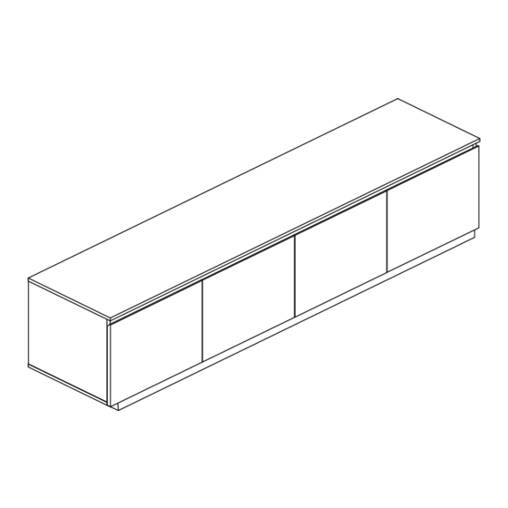
- Page 1 SBMETVWH SBMETVNT ASSEMBLY INSTRUCTIONS Memo Entertainment Unit www.templeandwebster.com.au...
- Page 2 Keep these instructions for future reference Read these instructions and follow steps carefully to ensure you assemble the product correctly and avoid damages. Check that all parts and hardware have been provided before assembling the product. Place all contents on a clean, soft-flat surface to avoid scratching the product.
- Page 3 WARNING: It is STRONGLY RECOMMENDED that you ANCHOR this product. Toppling furniture can cause serious injuries and death. This product has been s with a strap. To prevent your furniture from tipping forward it is strongly recommended that you securely attach this product to a wall or other solid surface, using the straps provided and appropriate fixings.
-
Page 4: Tools Required
Tools Required Time Required DO NOT USE 30 min Parts List (P1). Top panel, x1 (P2). Bottom panel, x1 (P3). Left side panel, x1 (P4). Right side panel, x1 (P5). Divider, x1 (P6). Front support rail, x1 (P1) (P7). Back panel, x2 (P8). - Page 5 45pcs 45pcs Hinge 8sets Hinge 4pcs wall...
- Page 6 (P8) (P9) (P8) (P8) (P9) This is how a cam nut works..The head of the cam bolt goes into the open mouth of the cam nut. You then turn the cam nut so it tightens over the bolt. (P9) Screw 12 x Cam bolts (1) into 2x Base long support rails (P8) using a screwdriver as shown.
- Page 7 (P2) Screw 6 x Cam bolts (1) into Bottom panel (P2) using a screwdriver as shown. Insert 6 x Dowels (3) into Bottom panel (P2). (P5) (P2) Position Divider (P5) onto Bottom panel (P2). Insert 2 x Cam nuts (2) into Divider (P5). Use a screwdriver to turn Cam nuts (2) clockwise to lock.
- Page 8 (P6) (P6) (P5) Screw 2 x Cam bolts (1) into Front support rail (P6) using a screwdriver as shown. Position Front support rail (P6) to Divider (P5). Insert 2 x Cam nuts (2) into Divider (P5), use a screwdriver to turn clockwise to lock. (P3) (P4) Screw 4 x Cam bolts (1) into Left side panel (P3) and Right side panel (P4) using a screwdriver as shown.
- Page 9 (P4) (P6) (P3) (P2) (P6) (P3) Position Left side panel (P3), Right side panel (P4) onto Bottom panel (P2). Gently attach Left side panel (P3) and Right side panel (P4) to Front support rail (P6) as shown. (P4) (P6) (P3) Insert 8 x Cam nuts (2) into Left side panel (P3), Right side panel (P4) and Front support rail (P6).
- Page 10 (P7) (P4) (P7) (P5) (P2) (P3) Insert 2x Back panels (P7) into the grooves of Left side panel (P3), Right side panel (P4), Divider (P5) and Bottom panel (P2). (P1) Screw 10 x Cam bolts (1) into Top panel (P1) using a screwdriver as shown. Fix the 2x Wall straps (8) with 2 x Screws (10) and 2 x Washers (9) to the Top panel (P1) as shown.
- Page 11 (P1) (P4) (P5) (P3) Insert 6 x Dowels (3) into Left side panel (P3), Divider (P5) and Right side panel (P4) as shown. Position Top panel (P1) onto the assembled frame. Insert 10 x Cam nuts (2) into Left side panel (P3), Right side panel (P4), Divider (P5) and Front support rail (P6). Use a screwdriver to turn clockwise to lock.
- Page 12 (P4) (P13) (P5) (P11) (P3) (P10) Attach the 2 x Doors (P10) and (P13) to Left side panel (P3) and Right side panel (P4) with 16 x Screws (6) using a screwdriver as shown. Attach the 2 x Doors (P11) and (P12) to Divider (P5) with 16 x Screws (6) using a screwdriver. If necessary, adjust the Hinges (4) and (5) using a Screwdriver.
- Page 13 Fix 8x Back panel holders (7) to assembled unit with 8x Screws using a screwdriver. wall Move the ETU into position against a wall. Mark suitable positions for the wall fixings. Follow instructions to install the wall fixings onto the wall. Reposition the ETU and fix the Wall straps (8) and 2 x Washers (9) to the wall with wall fixing.
Need help?
Do you have a question about the SBMETVWH and is the answer not in the manual?
Questions and answers