
Related Manuals for Emerson Bettis 2000 Series


Summary of Contents for Emerson Bettis 2000 Series
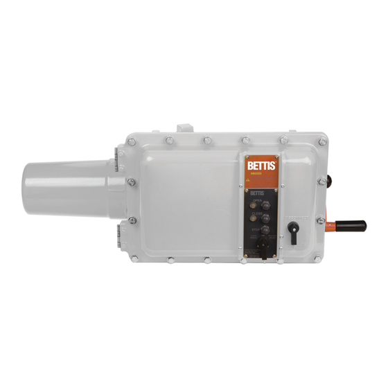
- Page 1 Installation, Operation and Maintenance Manual MAN-02-04-55-0735-EN Rev. 0 July 2019 Bettis 2000 Series M2CP User Manual...
-
Page 3: Table Of Contents
Installation, Operation and Maintenance Manual Table of Contents MAN-02-04-55-0735-EN Rev. 0 July 2019 Table of Contents Section 1: Introduction Section 2: Features and Specifications Section 3: Installation and Wiring Section 4: Module Setup and Calibration Indicator Lights ..................... 6 4.1.1 LED 1 .................... -
Page 4: Section 1: Introduction
Installation, Operation and Maintenance Manual Section 1: Introduction July 2019 MAN-02-04-55-0735-EN Rev. 0 This document covers the current Digital Futronic firmware version (Ver 4.6 released July 2019) and also references previous versions where applicable. Section 1: Introduction The Digital Futronic module uses the latest integrated microcontroller technology to enable one electronics module to perform valve actuator modulating and positioning control from analog control signals. -
Page 5: Section 2: Features And Specifications
Installation, Operation and Maintenance Manual Section 2: Features and Specifications July 2019 MAN-02-04-55-0735-EN Rev. 0 Section 2: Features and Specifications Digital microcontroller adapts to any actuator and valve size, speed/stroke-time, process pressure, etc. by automatically tuning controls to obtain maximum accuracy without any user adjustments for deadband, delay time, etc. -
Page 6: Section 3: Installation And Wiring
Section 3: Installation and Wiring Installation, Operation and Maintenance Manual July 2019 MAN-02-04-55-0735-EN Rev. 0 Section 3: Installation and Wiring Refer to the wiring diagram supplied with the actuator for wiring details and options supplied with the system. Figure 2 below is generic and provided primarily for wiring 4-20mA analog input and output signals. - Page 7 Installation, Operation and Maintenance Manual Section 3: Installation and Wiring July 2019 MAN-02-04-55-0735-EN Rev. 0 Figure 2 TBM01 Futronic Wiring NOTE: Refer to wiring diagram supplied with actuator for wiring details and options. Important Jumper J8 located on the bottom of TBM01 must be in the 24V position before the Digital Futronic card will operate.
-
Page 8: Section 4: Module Setup And Calibration
Section 4: Module Setup and Calibration Installation, Operation and Maintenance Manual July 2019 MAN-02-04-55-0735-EN Rev. 0 Section 4: Module Setup and Calibration DIP Switch SW3 has 6 switches designated as S1-S6 for calibration and mode selection as summarized below. There are two miniature push buttons labeled UP and DOWN. Refer to Figure 3 for location of DIP switches and push buttons. -
Page 9: Indicator Lights
Installation, Operation and Maintenance Manual Section 4: Module Setup and Calibration July 2019 MAN-02-04-55-0735-EN Rev. 0 Indicator Lights 4.1.1 LED 1 • Slow Flash = Normal Operating Mode. • Rapid Flash = Setup mode (any one of switches S1 through S3 are on). •... -
Page 10: Digital Futronic Number Type Display (New For Ver 4.6)
Section 4: Module Setup and Calibration Installation, Operation and Maintenance Manual July 2019 MAN-02-04-55-0735-EN Rev. 0 4.2.2 Digital Futronic Number Type Display (New for Ver 4.6) Digital Futronic firmware Ver 4.6 will display additional information on LED1 following flash sequence shown in 4.2.1. On power up, LED1 will display Actuator Type which is currently configured after it displays firmware version. -
Page 11: Cal Analog Input (S1 On)
Installation, Operation and Maintenance Manual Section 4: Module Setup and Calibration July 2019 MAN-02-04-55-0735-EN Rev. 0 4.3.2 Cal Analog Input (S1 ON) Press UP to set Span (20mA) Input - Figure 5. Press DOWN button to set Zero (4mA) Input - Figure 5. Figure 5 4.3.3 Cal Analog Output Zero (S2 ON) -
Page 12: Set Modulation Delay (S1, S2 On)
Section 4: Module Setup and Calibration Installation, Operation and Maintenance Manual July 2019 MAN-02-04-55-0735-EN Rev. 0 4.3.5 Set Modulation Delay (S1, S2 ON) Press UP to select 3-Ph motor (delay = 2 sec) - Figure 8. Press DOWN to select 1-Ph motor (delay = 12 sec) - Figure 8. Figure 8 4.3.6 Set Default Position (S2 &... -
Page 13: Invert Analog I/O (S1, S2 & S3 On)
Installation, Operation and Maintenance Manual Section 4: Module Setup and Calibration July 2019 MAN-02-04-55-0735-EN Rev. 0 4.3.7 Invert Analog I/O (S1, S2 & S3 ON) Press UP to Select Inverted Mode - Figure 10. Press DOWN to Disable Inverted Mode - Figure 10. Figure 10 4.3.8 Double Deadband (S1 &... -
Page 14: 2% Deadband (S1, S3, S4 On)
Section 4: Module Setup and Calibration Installation, Operation and Maintenance Manual July 2019 MAN-02-04-55-0735-EN Rev. 0 4.3.9 2% Deadband (S1, S3, S4 ON) Press UP to Select 2% control deadband. See Note (2) - Figure 12. Press DOWN to Select 1.5% control deadband - Figure 12. Figure 12 NOTE: (1) Doubling the control deadband (bandwidth) reduces control accuracy by twice the... -
Page 15: Pulsing Control (S1, S2, S3, S4, S6 On & S5 Off)
Installation, Operation and Maintenance Manual Section 4: Module Setup and Calibration July 2019 MAN-02-04-55-0735-EN Rev. 0 4.3.10 Pulsing Control (S1, S2, S3, S4, S6 ON & S5 OFF) Press UP to Select Pulsing Control - Figure 13. Press DOWN to Disable Pulsing Control to default values - Figure 13. Figure 13 NOTE New for firmware Ver 4.6, default setting for Pulsing Control is OFF/Disabled. -
Page 16: Mode Selection
Section 4: Module Setup and Calibration Installation, Operation and Maintenance Manual July 2019 MAN-02-04-55-0735-EN Rev. 0 Mode Selection S4 ON = Go to Default Position on loss of analog input control signal - Figure 14. S4 OFF = Stay put on loss of analog input control signal - Figure 14. Figure 14 S5 OFF and S6 OFF >... -
Page 17: Calibration Procedures
Installation, Operation and Maintenance Manual Section 4: Module Setup and Calibration July 2019 MAN-02-04-55-0735-EN Rev. 0 Calibration Procedures CAUTION Place selector switch in “OFF” position before calibrating actuator. 4.5.1 Calibrate Analog Input (Position Command Signal) Connect 4-20mA calibration source to TBM Terminals 52 (-) and 53 (+). Set S1 to ON (up) position. -
Page 18: Calibrate Analog Output (Position Feedback)
Section 4: Module Setup and Calibration Installation, Operation and Maintenance Manual July 2019 MAN-02-04-55-0735-EN Rev. 0 4.5.2 Calibrate Analog Output (Position Feedback) Connect calibrated 4-20mA meter to TBM Terminals 50 (-) and 51 (+). Set S2 to ON (up) position. Press UP or DOWN push button to increase or decrease zero (4mA) analog output signal. -
Page 19: Enable/Disable Go-To-Position On Loss Of Signal
Installation, Operation and Maintenance Manual Section 4: Module Setup and Calibration July 2019 MAN-02-04-55-0735-EN Rev. 0 4.5.4 Enable/Disable Go-To-Position on Loss of Signal Set S4 ON (up) to Enable Go-To-Position on loss of signal. Set S4 OFF (down) to Disable Go-To-Position on loss of signal, i.e. Stay in last position on loss of signal. -
Page 20: Assign Digital Futronic Type (New For Ver 4.6)
Section 4: Module Setup and Calibration Installation, Operation and Maintenance Manual July 2019 MAN-02-04-55-0735-EN Rev. 0 4.5.6 Assign Digital Futronic Type (New for Ver 4.6) Firmware Ver 4.6 requires the Digital Futronic type to be actively configured. Previous firmware Ver 4.2 and below only require setting the DIP Switches S5 and S6. Set DIP Switches S5 and S6 (See Table 1) to assign Digital Futronic type. -
Page 21: Appendix A: Definitions
Installation, Operation and Maintenance Manual Appendix July 2019 MAN-02-04-55-0735-EN Rev. 0 Appendix A: Definitions Command = 4-20mA analog input position command signal generated by remote • control equipment. Same as position command setpoint. Zero and Full-scale calibrated by user. • Position = 0-5V valve position analog input signal generated by Hall-effect Position Sensor (HPS). - Page 22 Appendix Installation, Operation and Maintenance Manual July 2019 MAN-02-04-55-0735-EN Rev. 0 • Open Coast = Difference between Position when the motor is turned off and Position when the valve stops moving in the open direction. The controller measures open coast to automatically tune control for maximum accuracy. •...
- Page 24 Tianjin 301700 Holland Fasor 6 P. R. China Székesfehérvár 8000 The Emerson logo is a trademark and service mark of Emerson Electric Co. T +86 22 8212 3300 Hungary is a mark of one of the Emerson family of companies.
Need help?
Do you have a question about the Bettis 2000 Series and is the answer not in the manual?
Questions and answers