Advertisement
Quick Links
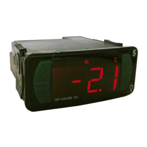
1. DESCRIPTION
Designed to maximize energy efficiency in commercial refrigeration equipment, the MT-444
features pluggable terminal block for quick coupling, increasing productivity in manufacturing lines. It is
equipped with 4 output relays (compressor, fan, defrost and light), 2 temperature sensors and one digital
input. It can be configured with 3 independent sets of parameters for quick change of (setpoint, eco-
setpoint, differential and defrost) settings to accommodate change of product in the room. Digital input
can be programmed to activate/deactivate economic set point, initiate defrost, door ajar alarms, door
open counter or light control. Light and economy set point can also be controlled through quick access
menu key, eliminating the need of external switches. Other salient features include temperature initiated
defrost, internal buzzer, IP65 frontal, drip protection case on rear, min-max temperature record, serial
programming key, multi LED color options and functions lockdown to prevent unauthorized parameter
changes.
Product conforming to UL Inc. (United States and Canada).
2. SAFETY RECOMMENDATIONS
- Check the controller for correct fastening;
- Make sure that the power supply is off and that it is not turned on during the controller installation;
- Read the present manual before installing and using the controller;
- Use adequate Personal Protective Equipmenet (PPE);
- For application at sites subject to water spills, such as refrigerated counters, install the protecting vinyl
supplied with the controller;
- For protection under more critical conditions, we recommend the Ecase cover, which we make available
as an optional item (sold separately);
- The installation procedures should be performed by a qualified technician.
3. APPLICATIONS
• Beverage displays;
• Reach-in coolers;
• Refrigeration counters;
• Up right freezers.
4.TECHNICAL SPECIFICATIONS
Power supply
Approximate consumption
Setpoint Temperature
Operating Temperature
Operating humidity
Maximum current per output
Digital input
Maximum dimensions (**) (mm)
Cutouts dimensions (mm)
(*) Admissible variation in relation to the voltage rating.
(**) Maximum dimensions without connectors.
5. INDICATORS AND KEYS
Refrigeration indicator LED
Light indicator LED
Power-saving mode indicator LED
Quick Access
Menu Key (Flatec)
Set Key
e
MT-444
6. WIRING DIAGRAM
Image I - Connection 115 Vac
DIG
1
2 3 4
9 10 11 12 13 14 15 16 17
5 6 7 8
LIGHT
FAN
Image III - Connection 12 Vac/dc
DIG
1
2 3 4
9 10 11 12 13 14 15 16 17
5 6 7 8
LIGHT
12 Vac/dc
MT-444
Buzzer
Connector
Power-saving
On/off
for quick
mode
light
coupling
MT-444E Fit: 115 or 230Vac ±10%(*) (50/60 Hz)
MT-444EL Fit: 12 or 24Vac/dc +10%(*)
3.4 VA
- 50 to 75°C (-58 to 167°F)
-10 to 50°C / 14 to 122°F
10 to 90% RH (without condensation)
COMP: 12(8)A / 240Vac 1HP
DEFR: 3A / 240Vac 720W
FAN: 5(3)A / 240Vac
LIGHT: 5(3)A / 240Vac
input for open-door detection (dry contact type)
76 x 34 x 77 (WxHxD)
X = 71±0,5 Y = 29±0,5 (see Image V)
Fan indicator LED
Defrost indicator LED
Temperature unit indicator LED
Image II - Connection 230 Vac
DIG
1
2 3 4
5 6 7 8
DEFR
COMP
115 Vac
Image IV - Connection 24 Vac/dc
DIG
1
2 3 4
5
6 7 8
FAN
DEFR
COMP
Loads supply
e
Fit
IP 65
FRONT
Functions
Control
Serial
Protection
lock
functions
Programming
level
shutdown
NEW FIT CONNECTION SYSTEM (QUICK COUPLING)
e
Fit
Signal connection
with lock
6.1. Temperature sensor connection
- Connect the sensor S1 wires to terminals "1 and 2" and wires sensor S2 to terminals "3 and 4": the
polarity is not relevant.
- Length of the sensor cables can be increased by user himself to up to 200 meters, using a PP 2x24 AWG
cable.
6.2. Recommendations of IEC60364 standard
a) Install overload protectors in the controller supply.
b) Install transient suppressors – suppressor filter RC – in the circuit to increase the service life of the
controller relay. See connection instructions of the filter on the previous page.
c) The sensor cables may be together, but not in the same conduit where the power supply of the
controller and/or of the loads passes through.
Upper key
Lower key
9 10 11 12 13 14 15 16 17
LIGHT
FAN
DEFR
COMP
230 Vac
9 10
12 13 14 15 16 17
LIGHT
FAN
DEFR
COMP
Loads supply
24 Vac/dc
evolution
e
e
M T- 44 4
M T- 44 4
E251415
Connection block for
power outputs
IMPORTANT
It is essential to use the correct
tools in order to avoid damages
to the instrument's connection
terminals:
Controller power supply
Use the pins according to table below, considering the set version:
Pins
MT-444E Fit
9 and 10
115 Vac
9 and 11
230 Vac
The sensor S1 must be in the ambient.
The sensor S2 must be placed in the evaporator
through metallic cramp.
MT-444EL Fit
12 Vac/dc
24 Vac/dc
Advertisement

Related Manuals for Full Gauge Controls MT-444e Fit


Summary of Contents for Full Gauge Controls MT-444e Fit
- Page 1 - Connect the sensor S1 wires to terminals "1 and 2" and wires sensor S2 to terminals "3 and 4": the polarity is not relevant. MT-444E Fit: 115 or 230Vac ±10%(*) (50/60 Hz) Power supply - Length of the sensor cables can be increased by user himself to up to 200 meters, using a PP 2x24 AWG MT-444EL Fit: 12 or 24Vac/dc +10%(*) cable.
- Page 2 8. QUICK ACCESS MENU AND BASIC OPERATIONS 8.7 Display process stage and current setpoint > 8.1. Quick Access Menu Map To see which process stage is underway, press and hold the key for 4s, until the[Proc]message appears. Then release it. The stage of the process which is in progress will be displayed, showing the You can navigate through the function menus by pressing the key (Flatec).
-
Page 3: Advanced Operations
8.11 View the number of times the door was opened 9.3 Functions lock The use of the functions lock brings greater security to the operation oh the instrument. When it is active The numberof times the door was opened can be viewed by pressing the key (quick touch) until the the presets and other parameters can be visible to the user, but are protected against undue message [door]is displayed, and then the number is shown. - Page 4 CELSIUS (FAHRENHEIT) FUNCTION DESCRIPTION UNIT. MÍN MÁX DEFAULT [,,,0]= Electrical defrost (by resistance), where only the defrost output is activated.. [,f22] Defrost type [,,,1]= Hot gas defrost, whereby the compressor and defrost output are activated.. [,,,2]= Natural defrost, where only the fan output is activated. [,,,0]= Defrost started by time;...
- Page 5 CELSIUS (FAHRENHEIT) FUNCTION DESCRIPTION UNIT. MÍN MÁX DEFAULT [no,,] - Digital input disabled; [,,,1] - Normally open contact (NO); [,f54] Digital Input operating mode ( Door Sensor) [no,,] [,,,2] - Normally closed contact (NC); If the door is kept open for a longer period than set with this function, an instant defrost will take place, provided that the evaporator temperature (sensor S2) is lower than [,f32], Door open time until instant defrost begins [,f55]...
- Page 6 FRAME SWITCHES EasyProg Products manufactured by Full Gauge Controls, as of May 2005, have a two (02) year - version 2 or higher warranty, as of the date of the consigned sale, as stated on the invoice. They are guaranteed It is an accessory that has as its main function to store the parameters of the controllers.
Need help?
Do you have a question about the MT-444e Fit and is the answer not in the manual?
Questions and answers