
Related Manuals for Samson 3323


Summary of Contents for Samson 3323
- Page 1 Series V2001 Type 3323 Three-way Valve Mounting and Operating Instructions EB 8113/8114 EN Edition August 2013...
- Page 2 Definition of signal words DANGER! NOTICE Hazardous situations which, if not Property damage message or mal- avoided, will result in death or seri- function ous injury Note: WARNING! Additional information Hazardous situations which, if not avoided, could result in death or se- Tip: rious injury Recommended action...
-
Page 3: Table Of Contents
Replacing the seat and/or plug ..............17 5.3.1 Valves in DN 15 and 25 ................17 5.3.2 Valves in DN 32 to 100 ................18 SAMSON seat wrench and tightening torques ..........22 Description of the nameplate ...............23 Dimensions ....................23 Customer inquiries ..................23 EB 8113/8114 EN... -
Page 5: General Safety Instructions
General safety instructions 1 General safety instructions − The control valve must be mounted, started up or serviced by fully trained and qualified personnel only; the accepted industry codes and practices are to be observed. Make sure employees or third persons are not exposed to any danger. -
Page 6: Design And Principle Of Operation
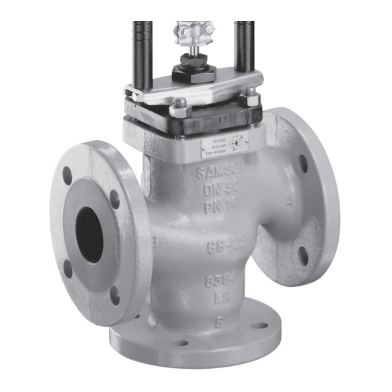
Design and principle of operation 2 Design and principle of oper- ation Fig. 1 The Type 3323 Three-way Valve has a mod- ular design and can be combined with pneu- matic or electric actuators (as described in the next section). Depending on the plug arrangement, the three-way valve can be used for either mix- ing or diverting service. - Page 7 Pipe (short) Stem connector 141 Seat Threaded bushing Plug stem 192 Retaining washer Spring Self-locking nut 199 Plug Fig. 1: Type 3323 as mixing valve in DN 32/50; detailed drawing (right) showing the plug arrangement of diverting valve EB 8113/8114 EN...
-
Page 8: Installation
Version with Type 3725 Positioner There are different ways to assemble the Type 3374 Actuator on Type 3323 Valve in valve and actuator depending on the actua- DN 65 (NPS 2½) and larger, Fig. 2 tor model and the nominal size. - Page 9 Installation Form B attachment (mounting using a central nut) Form C attachment (mounting using rods) Valve bonnet Stem connector Rods Crossbeam Plate Fig. 3: Form B attachment (mounting using a central nut) and Form C attachment (mounting using rods) EB 8113/8114 EN...
-
Page 10: Mounting Position
3.2 Mounting position 3.3 Strainer, bypass The valve can be mounted in any desired We recommend to install a SAMSON Type 2 position. However, the restrictions for the ac- Strainer upstream of the valve, and upstream tuator used must be strictly observed. - Page 11 Operation Mixing service - Temperature Diverting service - Flow control Actuator stem extends (FA) control Q = constant Q = 0 to 100 % Actuator stem retracts (FE) Flow pipe Heating with mixing valve FA Flow pipe Cooling with mixing valve FE Return flow pipe a) Installation in flow pipe Return flow...
-
Page 12: Maintenance - Replacing Parts
We recommend removing the valve from the pipeline. Valve bonnet We recommend removing the parts, cleaning Stem connector them, and, if necessary, replacing them with new ones. Fig. 5: Removing actuators from Type 3323 Valve up to DN 50 EB 8113/8114 EN... - Page 13 Stem connector Nuts Hexagon socket screws Plate Fig. 6: Removing Types 3371 and 3372 Actu- ators from Type 3323 Valve in DN 65 Fig. 7: Removing Type 3375 Actuator from and larger Type 3323 Valve in DN 65 and larger EB 8113/8114 EN...
-
Page 14: Replacing The Packing
Removing the valve bonnet, Fig. 8 Valve up to DN 50 Note: 1. Unscrew the threaded bushing (8). Contact your nearest SAMSON sub- 2. Unscrew nuts (14) and lift off flange sidiary or the SAMSON After-sales (2.1). Service department for information on suitable lubricants. - Page 15 Maintenance – Replacing parts 4. Use a suitable tool to pull the damaged packing (16) out of the valve bonnet. Remove washer (12) and spring (11) and clean the packing chamber. Installing the packing, Fig. 9 5. Apply a suitable lubricant to each part of the new packing as well as to the plug stem.
-
Page 16: Insulating Section
Maintenance – Replacing parts 5.2.2 Insulating section The arrangement of the packing in the insu- Fig. 10 lating section is the same as in the standard The insulating section is used to extend the bonnet. Proceed as described in section distance between the packing and the valve 5.2.1 to replace the packing. -
Page 17: Replacing The Seat And/Or Plug
Maintenance – Replacing parts 5.3 Replacing the seat and/or able tool and undo the nut (40) from be- low. plug 5. Remove the retaining washer (192) from Valves in DN 15 and 25 can be used both below. as mixing or diverting valves. The direction 6. -
Page 18: Valves In Dn 32 To 100
Maintenance – Replacing parts 8. Once the plug (5) has been removed, the Valve bonnet (DN 65 and larger) bottom seat (141) can also be removed 1. Unscrew the threaded bushing (8). using the seat wrench. 2. Remove nuts (14) and lift the valve bon- 9. - Page 19 Maintenance – Replacing parts Mixing valve Diverting valve DN 32 and 50 DN 32 and 50 DN 65 and higher DN 65 and higher Seat Self-locking nut 141 Seat Plug Pipe 192 Retaining washer Plug stem Pipe (short) 199 Plug Fig.
- Page 20 Maintenance – Replacing parts 4. Remove the retaining washer (192) and 5. Slide the bottom pipe (74) and retaining pipe (74) from below. Carefully pull the washer (192) from below onto the plug plug stem out of the body from above. stem and tighten the nut (40), while hold- The pipes (74, 75) for fixing the plug in ing the plug stem stationary.
- Page 21 Maintenance – Replacing parts Valve up to DN 50 Valve in DN 65 and larger 3. Place flange (2.1) on the bonnet and fas- 3. Fasten the bonnet with the nuts (14). ten with the nuts (14) (observe tightening 4. Apply a suitable lubricant to the thread torque in Table 1).
-
Page 22: Samson Seat Wrench And Tightening Torques
Maintenance – Replacing parts 5.4 SAMSON seat wrench and tightening torques Contact the SAMSON After-sales Service for more details on mounting. Table 1: SAMSON seat wrench and tightening torques DN 15 to 25 DN 32 to 50 DN 65 to 80 DN 100 Nominal size NPS ½... -
Page 23: Description Of The Nameplate
Description of the nameplate 6 Description of the nameplate 7 Dimensions The dimensions for the DIN and ANSI ver- sions of the Type 3323 Valve can be found SAMSON in the associated Data Sheets T 8113 EN T 8114 EN 11 12 Fig. - Page 24 SAMSON AG · MESS- UND REGELTECHNIK Weismüllerstraße 3 · 60314 Frankfurt am Main, Germany Phone: +49 69 4009-0 · Fax: +49 69 4009-1507 EB 8113/8114 EN samson@samson.de · www.samson.de...
Need help?
Do you have a question about the 3323 and is the answer not in the manual?
Questions and answers