Table of Contents
Advertisement
Quick Links
Advertisement
Table of Contents

Related Manuals for Samson 3323


Summary of Contents for Samson 3323
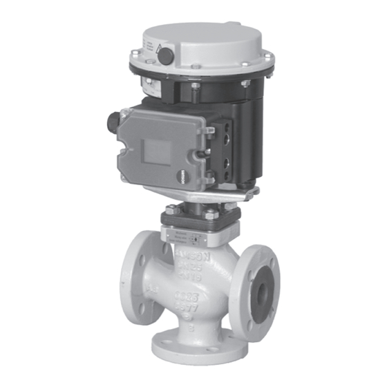
- Page 1 EB 8113/8114 EN Translation of original instructions Type 3323 Valve · DIN and ANSI versions In combination with actuators, e.g. SAMSON Type 3372 Electropneumatic Actuator, Type 3371 Pneumatic Actuator, Type 5824, Type 5827 or Type 3374 Electric Actuator Edition November 2022...
- Page 2 Note on these mounting and operating instructions These mounting and operating instructions assist you in mounting and operating the device safely. The instructions are binding for handling SAMSON devices. The images shown in these instructions are for illustration purposes only. The actual product may vary.
-
Page 3: Table Of Contents
Contents Safety instructions and measures ..............1-1 Notes on possible severe personal injury ............1-4 Notes on possible personal injury ..............1-5 Notes on possible property damage .............1-7 Warnings on the device ................1-8 Markings on the device ................2-1 Valve nameplate ..................2-1 Actuator nameplate ..................2-2 Material identification number ..............2-2 Label when an adjustable packing is installed ..........2-2 Design and principle of operation ...............3-1... - Page 4 Removal ....................11-1 11.1 Removing the valve from the pipeline ............11-2 11.2 Removing the actuator from the valve ............11-2 Repairs ....................12-1 12.1 Returning devices to SAMSON ..............12-1 Disposal ....................13-1 Certificates ....................14-1 Annex......................15-1 15.1 Tightening torques, lubricants and tools ............15-1 15.2 Spare parts ....................15-1 15.3...
-
Page 5: Safety Instructions And Measures
SAMSON. SAMSON does not assume any liability for damage resulting from the failure to use the de- vice for its intended purpose or for damage caused by external forces or any other external factors. - Page 6 Î Check with the plant operator for details on further protective equipment. Revisions and other modifications Revisions, conversions or other modifications of the product are not authorized by SAMSON. They are performed at the user's own risk and may lead to safety hazards, for example. Fur- thermore, the product may no longer meet the requirements for its intended use.
- Page 7 Start-up and shutdown procedures fall within the scope of the operator's duties and, as such, are not part of these mounting and operating instructions. SAMSON is unable to make any statements about these procedures since the operative details (e.g. differential pressures and temperatures) vary in each individual case and are only known to the operator.
-
Page 8: Notes On Possible Severe Personal Injury
> About SAMSON > Material Compliance > REACH If a device contains a substance listed as a substance of very high concern on the candi- date list of the REACH regulation, this is indicated on the SAMSON delivery note. 1.1 Notes on possible severe personal injury DANGER Risk of bursting in pressure equipment. -
Page 9: Notes On Possible Personal Injury
Risk of personal injury due to preloaded springs. Valves in combination with pneumatic actuators with preloaded springs are under ten- sion. These control valves with SAMSON pneumatic actuators can be identified by the long bolts protruding from the bottom of the actuator. - Page 10 Safety instructions and measures WARNING Crush hazard arising from moving parts. The control valve contains moving parts (actuator and plug stem), which can injure hands or fingers if inserted into the valve. Î Do not insert hands or finger into the yoke while the valve is in operation. Î...
-
Page 11: Notes On Possible Property Damage
Î Observe the specified tightening torques (u AB 0100). Risk of valve damage due to the use of unsuitable tools. Certain tools are required to work on the valve. Î Only use tools approved by SAMSON (u AB 0100). EB 8113/8114 EN... -
Page 12: Warnings On The Device
The lubricants to be used depend on the valve material. Unsuitable lubricants may cor- rode and damage surfaces. Î Only use lubricants approved by SAMSON (u AB 0100). Risk of the process medium being contaminated through the use of unsuitable lubri- cants and/or contaminated tools and components. -
Page 13: Markings On The Device
Fig. 2-3 and the inscription table list all pos- M: mixing valve · V: diverting valve sible characteristics and options that may appear on a valve nameplate. Only the in- scriptions relevant to the ordered Type 3323 Valve actually appear on the nameplate. EB 8113/8114 EN... -
Page 14: Actuator Nameplate
15 Noise reduction: 1: flow divider (ST) 1 · 2: ST 2 · by SAMSON. The material number enables 3: ST 3 · 1/PSA: ST 1 standard and inte- you to view the device's technical data as grated in seat for PSA valve ·... - Page 15 Markings on the device Fig. 2-4: Label when an adjustable packing is installed EB 8113/8114 EN...
- Page 16 EB 8113/8114 EN...
-
Page 17: Design And Principle Of Operation
Depending on the plug arrangement, the connector and sealed by the spring-loaded Type 3323 Three-way Valve can be used ei- packing. ther as a mixing or diverting valve. The de- The medium flows through the valve in the sign of the mixing and diverting valves in direction indicated by the arrow. - Page 18 Design and principle of operation 2 Plug stem 51 Stud 17 Plug 52 Body nut 20 Body 121 Hex nut (self-locking) 27 Valve bonnet 123 Washer 34 Flange 131 Threaded bushing (packing nut) 40 Spacer 133 V-ring packing 41 Spacer 135 Central nut 44 Spacer 161 Bottom seat...
-
Page 19: Fail-Safe Action
The fail- The direction of action of the Type 3371 safe action of SAMSON actuators is Pneumatic Actuator can be reversed, if re- specified on the actuator nameplate. quired. See the mounting and operating in- structions u EB 8317. -
Page 20: Additional Fittings
Noise emissions Insulation SAMSON is unable to make general state- Control valves can be insulated to reduce ments about noise emissions. The noise emis- heat energy transfer. Refer to the instructions sions depend on the valve version, plant fa- in the 'Installation' section. - Page 21 Design and principle of operation Table 3-1: Technical data · DIN version Cast iron · Sph. gr. iron Material · EN-GJS- Cast steel · 1.0619 Stainless steel 1.4408 GJL-250 400-18-LT Valve size 15 to 100 15 to 100 15 to 50 65 to 100 15 to 50 65 to 100...
- Page 22 Design and principle of operation Table 3-3: Dimensions and weights for Type 3323 Valve · DIN version Valve Dimension A H4 (with ins. section) Weight Weight (with insulating section) Table 3-4: Dimensions and weights for Type 3323 Valve · ANSI version ½...
- Page 23 Design and principle of operation Dimensional drawings DN 15 to 50/NPS ½ to 2 DN 65 to 100/NPS 2½ to 4 Version with insulating section DN 15 to 50/NPS ½ to 2 DN 65 to 100/NPS 2½ to 4 EB 8113/8114 EN...
- Page 24 Design and principle of operation Note Refer to the following data sheets for more dimensions and weights of the actuators: u T 8313 for Type 3372 Electropneumatic Actuator u T 8317 for Type 3371 Pneumatic Actuator u T 5824 for Type 5824 Electric Actuator u T 5827 for Type 5827 Electric Actuator u T 8331 for Type 3374 Electric Actuator EB 8113/8114 EN...
-
Page 25: Shipment And On-Site Transport
2. Check the shipment for transportation Î Stay clear of suspended or moving damage. Report any damage to loads. SAMSON and the forwarding agent Î Close off and secure the transport paths. (refer to delivery note). 3. Determine the weight and dimensions of... - Page 26 Shipment and on-site transport WARNING NOTICE Risk of personal injury due to the control Risk of valve damage due to incorrectly valve tipping over. attached slings. Î Observe the valve's center of gravity. Î When lifting the control valve, make sure Î...
-
Page 27: Transporting The Valve
Shipment and on-site transport 4.3.1 Transporting the valve ping off the hook during lifting and transporting. The control valve can be transported using − Secure slings against slipping. lifting equipment (e.g. crane or forklift). − Make sure the slings can be removed Î... -
Page 28: Storing The Valve
Elastomer, e.g. actuator diaphragm Î Avoid long storage times. − To keep elastomers in shape and to pre- Î Contact SAMSON in case of different vent cracking, do not bend them or hang storage conditions or longer storage them up. -
Page 29: Installation
Installation 5 Installation 5.1 Installation conditions The work described in this section is only to Work position be performed by personnel appropriately The work position for the control valve is the qualified to carry out such tasks. front view looking onto the operating con- Table 5-1: Inlet and outlet lengths Flow rate Inlet length... - Page 30 Î Contact SAMSON if the mounting posi- tion. tion is not as specified above. Pipeline routing...
- Page 31 Installation FA: Actuator stem extends Mixing service – Temperature Diverting service – Flow control Q control Q = constant = 0 to 100 % FE: Actuator stem retracts Heating with mixing valve (FA) Flow pipe Flow pipe Cooling with mixing valve (FE) a) Installation in flow pipe Return flow b) Installation in return flow...
-
Page 32: Preparation For Installation
Installation Î Locate the vent plug on the opposite side Î Flush the pipelines. to the work position of operating person- nel. Note The plant operator is responsible for clean- 5.2 Preparation for installation ing the pipelines in the plant. Before installation, make sure the following Î... -
Page 33: Mounting The Actuator Onto The Valve
Risk of valve damage due to the use of using a crossbeam (form B, Fig. 5-2), the ac- unsuitable tools. tuator is fastened to the valve bonnet using a Î Only use tools approved by SAMSON central nut. (u AB 0100). Mounting using rods When the actuator is mounted using rods 5.3.1... - Page 34 Installation Type 3323-PP Type 3323-IP Type 3323-E1 Type 3323-E3 Fig. 5-2: Mounting using crossbeam and central nut (form B attachment) Type 3323-PP Type 3323-IP Fig. 5-3: Mounting using rods (form C attach- ment) Legend for Fig. 5-2 and Fig. 5-3 Central nut Crossbeam Plate EB 8113/8114 EN...
-
Page 35: Installing The Valve Into The Pipeline
Installation 5.3.2 Installing the valve into Î Drain the process medium from all the plant sections concerned as well as the the pipeline valve. 1. Close the shut-off valves in the pipeline at the inlet and outlet of the plant section WARNING WARNING while the valve is being installed. -
Page 36: Leak Test
Installation lease any stored energy in the actuator To test the valve functioning before start-up (e.g. spring compression). See associat- or putting back the valve into operation, per- ed actuator documentation. form the following tests: 5.4.1 Leak test WARNING WARNING The plant operator is responsible for per- Risk of personal injury due to exhaust air forming the leak test and selecting the test... -
Page 37: Fail-Safe Position
Installation Î Apply the maximum and minimum con- trol signals to check the end positions of the valve while observing the movement of the actuator stem. Î Check the travel reading at the travel in- dicator scale. 5.4.3 Fail-safe position Î... - Page 38 5-10 EB 8113/8114 EN...
-
Page 39: Start-Up
Start-up 6 Start-up WARNING WARNING The work described in this section is only to Crush hazard arising from actuator and be performed by personnel appropriately plug stem moving. qualified to carry out such tasks. Î Do not insert hands or finger into the yoke while the valve is in operation. - Page 40 Start-up Before start-up or putting the valve back into service, make sure the following conditions are met: − The valve is properly installed into the pipeline (see the 'Installation' section). − The leak and function tests have been completed successfully (see the 'Testing the installed valve' section).
-
Page 41: Operation
Operation 7 Operation WARNING WARNING Immediately after completing start-up or put- Crush hazard arising from actuator and ting the valve back into operation (see the plug stem moving. 'Start-up' section), the valve is ready for use. Î Do not insert hands or finger into the yoke while the valve is in operation. - Page 42 EB 8113/8114 EN...
-
Page 43: Malfunctions
Malfunctions 8 Malfunctions Read hazard statements, warnings and caution notes in the 'Safety instructions and mea- sures' section. 8.1 Troubleshooting Malfunction Possible reasons Recommended action Actuator and plug stem Actuator is blocked. Check attachment. does not move on de- Remove the blockage. mand. -
Page 44: Emergency Action
Malfunctions Malfunction Possible reasons Recommended action Increased flow through Dirt or other foreign Shut off the section of the pipeline and flush the closed valve (seat leak- particles deposited valve. age) between the seat and plug. Valve trim is worn out. Replace seat and plug (see the 'Servicing' section) or contact our after-sales service. -
Page 45: Servicing
Servicing 9 Servicing WARNING The work described in this section is only to Risk of burn injuries due to hot or cold be performed by personnel appropriately components and pipeline. qualified to carry out such tasks. Valve components and the pipeline may be- come very hot or cold. - Page 46 NOTICE Risk of valve damage due to the use of unsuitable tools. WARNING Î Only use tools approved by SAMSON Risk of personal injury due to preloaded (u AB 0100). springs. Actuators with preloaded springs are under tension.
-
Page 47: Periodic Testing
Servicing 9.1 Periodic testing Note The control valve was checked by SAMSON Depending on the operating conditions, before it left the factory. check the valve at certain intervals to prevent − Certain test results certified by SAMSON possible failure before it can occur. Plant op-... -
Page 48: Preparing The Valve For Service Work
Servicing Inspection and testing Action to be taken in the event of a negative result: Check the valve's seat leakage. Shut off the section of the pipeline and flush the valve to re- move any dirt and/or deposited foreign particles between the seat and plug. -
Page 49: Mounting The Valve After Service Work
Servicing 9.4.1 Replacing the gasket − Replace the gaskets as described in sec- tion 9.4.1. − Replace the packing (see section 9.4.2) a) Valves up to DN 50/NPS 2 − Replace the seat and plug (see sec- tion 9.4.3) 1. Unscrew the threaded bushing (131). 2. - Page 50 Servicing 2 Plug stem 121 Hex nut (self-locking) 17 Plug 123 Washer 20 Body 131 Threaded bushing (packing nut) 27 Valve bonnet 134 V-ring packing 34 Flange 135 Central nut 40 Spacer 161 Bottom seat 41 Spacer 162 Top seat 44 Spacer A11 Rod 46 Body gasket...
-
Page 51: Replacing The Packing
(2). Note 5. Insert a new gasket (17) into the body. The Type 3323 Valve is either fitted with a 6. Carefully place the valve bonnet (2) over standard or form D packing. The packings the plug stem (36) and the studs (13) on- have an identical design, but contain differ- to the body (1). - Page 52 Servicing a) Valves up to DN 50/NPS 2 Valve bonnet 1. Unscrew the threaded bushing (131). 131 Threaded bushing 2. Undo the body nuts (52) gradually in a 132 Washer crisscross pattern. 133 Spring 3. Carefully lift the flange (34) and valve 134 V-ring bonnet (27) off the valve body (20) over packing...
-
Page 53: Replacing The Seat And Plug
Servicing 6. Apply a suitable lubricant to all the pack- Valve ing parts and to the plug stem (36). bonnet 7. Carefully place the valve bonnet (2) over Threaded bushing the plug stem (36) and the studs (13) 11 Spring onto the body (1). - Page 54 Servicing 10. Unscrew the bottom seat (161) using a suitable tool. When replacing the seat and plug, we also 11. Apply a suitable lubricant to the thread recommend replacing the gasket and pack- and the sealing cone of the new bottom ing.
- Page 55 Servicing b) Valves in DN 32 and 50/ NPS 3 and 4 On mounting the spacers (40, 41, 44) and plug (17), use a rod or long screw to hold them in position. Mixing valve 1. Unscrew the threaded bushing (131). 2. Undo the body nuts (52) gradually in a crisscross pattern.
- Page 56 Servicing 11. Apply a suitable lubricant to the thread and the sealing cone of the new seats (161, 162). 12. Screw in the bottom seat (161). Observe tightening torques. 13. Insert the bottom plug (17) into the bot- tom seat (161). 14.
- Page 57 Servicing Diverting valve 1. Unscrew the threaded bushing (131). 2. Undo the body nuts (52) gradually in a crisscross pattern. 3. Carefully lift the flange (34) and valve bonnet (27) off the valve body (20) over the plug stem (2). 4.
- Page 58 Servicing 19. Slide the retaining washer and shim Mixing valve (122, 123) from below onto the plug 1. Unscrew the threaded bushing (8). stem (2). 2. Undo the body nuts (14) gradually in a 20. Thread and tighten the hex nut (121) on- crisscross pattern.
- Page 59 Servicing 15. Carefully guide the plug stem (36) with 21. Carefully slide the packing parts over the top spacer (75) from above through the plug stem into the packing chamber us- top plug (5), short spacer (76) and bot- ing a suitable tool. Observe the proper tom plug (199).
- Page 60 Servicing 5. Remove the retaining washer (192) from 14. Use a suitable tool to catch the bottom the plug stem (36). plug (199) and the spacers (75, 76). 6. Hold the bottom plug (199). Carefully 15. Screw in the top seat (4). Observe tight- pull the plug stem (36) out of the body ening torques.
- Page 61 Servicing 22. Carefully place the valve bonnet (2) over the plug stem (36) and the studs (13) on- to the body (1). Make sure that the gas- ket (17) is properly seated in the body. 23. Carefully slide the packing parts over the plug stem into the packing chamber us- ing a suitable tool.
-
Page 62: Ordering Spare Parts And Operating Supplies
Servicing 9.5 Ordering spare parts and operating supplies Contact your nearest SAMSON subsidiary or SAMSON's After-sales Service for infor- mation on spare parts, lubricants and tools. Spare parts See Annex for details on spare parts. Lubricant See document u AB 0100 for details on suitable lubricants. -
Page 63: Decommissioning
Decommissioning 10 Decommissioning WARNING The work described in this section is only to Risk of hearing loss or deafness due to loud be performed by personnel appropriately noise. qualified to carry out such tasks. Noise emission (e.g. cavitation or flashing) may occur during operation caused by the process medium and the operating DANGER... - Page 64 Decommissioning 5. If necessary, allow the pipeline and valve WARNING WARNING components to cool down or warm up to Risk of personal injury due to exhaust air the ambient temperature. being vented from pneumatically operated components. While the valve is operating, air is vented from the actuator, for example, during closed-loop operation or when the valve opens or closes.
-
Page 65: Removal
Removal 11 Removal (e.g. spring compression). See associat- ed actuator documentation. The work described in this section is only to be performed by personnel appropriately qualified to carry out such tasks. WARNING WARNING Risk of personal injury due to residual WARNING process medium in the valve. -
Page 66: Removing The Valve From The Pipeline
Removal 11.1 Removing the valve from the pipeline 1. Support the valve to hold it in place when separated from the pipeline (see the 'Shipment and on-site transport' sec- tion). 2. Unbolt the flange joint. 3. Remove the valve from the pipeline (see the 'Shipment and on-site transport' sec- tion). -
Page 67: Repairs
Î Do not perform any repair work on your side of your shipment so that the docu- own. ments are clearly visible. Î Contact SAMSON's After-sales Service 4. Send the shipment to the address given for repair work. on the RMA. - Page 68 12-2 EB 8113/8114 EN...
-
Page 69: Disposal
Disposal 13 Disposal SAMSON is a producer registered at the following European institution u https://www.ewrn.org/nation- al-registers/national-registers. WEEE reg. no.: DE 62194439/ FR 02566 Î Observe local, national and internation- al refuse regulations. Î Do not dispose of components, lubricants and hazardous substances together with your household waste. - Page 70 13-2 EB 8113/8114 EN...
-
Page 71: Certificates
− Country of origin: France, see page 14-4 to 14-7 − Declaration of conformity in compliance with Machinery Directive 2006/42/EC for Types 3323-1 and 3323-7 Control Valves on page 14-8 − Declaration of incorporation in compli- ance with Machinery Directive 2006/42/EC for the Type 3323 Valve with other actuators other than Types 3271 and 3277 Actuators on... - Page 72 Modul A/Module A SAMSON erklärt in alleiniger Verantwortung für folgende Produkte:/For the following products, SAMSON hereby declares under its sole responsibility: Geräte/Devices Bauart/Series Typ/Type Ausführung/Version DIN, Gehäuse GG, DN 65-125, Gehäuse GGG, DN 50-80, Fluide G2, L1, L2 Durchgangsventil/Globe valve...
- Page 73 EB 8113/8114 EN 14-3...
- Page 74 DC014 Module A / Modul A 2022-05 Par la présente, SAMSON REGULATION SAS déclare sous sa seule responsabilité pour les produits suivants : For the following products, SAMSON REGULATION SAS hereby declares under its sole responsibility: Appareils / Exécution / Matériel du corps / body...
- Page 75 Modul A Normes techniques appliquées / Technical standards applied : DIN EN 12516-2, DIN EN 12516-3, ASME B16.34, DIN-EN 60534-4, DIN-EN 1092-1 Fabricant / manufacturer : Samson Régulation SAS, 1, rue Jean Corona, FR-69120 VAULX-EN-VELIN Vaulx-en-Velin, le 23/05/22 Bruno Soulas Joséphine Signoles-Fontaine...
- Page 76 Module H / Modul H, N°/ Nr CE-0062-PED-H-SAM 001-20-FRA-rev-A 2022-05 Par la présente, SAMSON REGULATION SAS déclare sous sa seule responsabilité pour les produits suivants : For the following products, SAMSON REGULATION SAS hereby declares under its sole responsibility: Appareils / Exécution /...
- Page 77 The manufacturer’s quality management system is monitored by the following notified body: Bureau Veritas Services SAS N°/Nr 0062, 8 Cours du Triangle, 92800 PUTEAUX - LA DEFENSE Fabricant / manufacturer : Samson Régulation SAS, 1, rue Jean Corona, FR-69120 VAULX-EN-VELIN Vaulx-en-Velin, le 23/05/22 Bruno Soulas Joséphine Signoles-Fontaine...
- Page 78 14-8 EB 8113/8114 EN...
- Page 79 EB 8113/8114 EN 14-9...
- Page 80 14-10 EB 8113/8114 EN...
- Page 81 Machinery components can be mounted onto the above specified final ma- chinery if they comply with the specifications and properties defined by SAMSON Manual H 02 “Ap- propriate Machinery Components for SAMSON Pneumatic Control Valves with a Declaration of Con- formity of Final Machinery”.
- Page 82 For the following product: Type 3323 Pneumatic Control Valve We certify that the Type 3323 Pneumatic Control Valves are partly completed machinery as defined in the in Directive 2008 No. 1597 Supply of Machinery (Safety) Regulations 2008 and that the safety requirements stip- ulated in Annex I, 1.1.2, 1.1.3, 1.1.5, 1.3.2, 1.3.4 and 1.3.7 are observed.
-
Page 83: Annex
Annex 15 Annex 15.1 Tightening torques, lubricants and tools u AB 0100 for tools, tightening torques and lubricants 15.2 Spare parts DN 65 to 100/NPS 2½ to 4 Body DN 15 to 50/NPS ½ to 2 Valve bonnet/insulating section Plug stem Top seat Guide bushing Top plug Plug Guide bushing Body... - Page 84 Annex DN 15 to 50/NPS ½ to 2 15-2 EB 8113/8114 EN...
- Page 85 Annex DN 65 to 100/NPS 2½ to 4 EB 8113/8114 EN 15-3...
-
Page 86: After-Sales Service
Addresses of SAMSON AG and its subsid- Importer iaries SAMSON Controls Ltd The addresses of SAMSON AG, its subsid- Perrywood Business Park iaries, representatives and service facilities Honeycrock Lane worldwide can be found on our website Redhill, Surrey RH1 5JQ (www.samsongroup.com) or in all SAMSON Phone: +44 1737 766391... - Page 88 EB 8113/8114 EN SAMSON AKTIENGESELLSCHAFT Weismüllerstraße 3 · 60314 Frankfurt am Main, Germany Phone: +49 69 4009-0 · Fax: +49 69 4009-1507 samson@samsongroup.com · www.samsongroup.com...
Need help?
Do you have a question about the 3323 and is the answer not in the manual?
Questions and answers