
Subscribe to Our Youtube Channel
Related Manuals for Samson 3321CT


Summary of Contents for Samson 3321CT
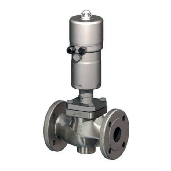
- Page 1 EB 8115 EN Translation of original instructions Type 3321CT Valve · DIN and ANSI versions For combining with actuators, e.g. Type 3379 Pneumatic Actuator Edition June 2022...
- Page 2 Note on these mounting and operating instructions These mounting and operating instructions assist you in mounting and operating the device safely. The instructions are binding for handling SAMSON devices. The images shown in these instructions are for illustration purposes only. The actual product may vary.
-
Page 3: Table Of Contents
Contents Safety instructions and measures ..............1-1 Notes on possible severe personal injury ............1-5 Notes on possible personal injury ..............1-5 Notes on possible property damage .............1-7 Markings on the device ................2-1 Valve nameplate ..................2-1 Actuator nameplate ..................2-1 Design and principle of operation ...............3-1 Fail-safe action ...................3-1 Additional fittings ..................3-1 Technical data ....................3-3... - Page 4 Ordering spare parts and operating supplies ..........9-9 Decommissioning ..................10-1 Removal ....................11-1 11.1 Removing the valve from the pipeline ............11-1 Repairs ....................12-1 12.1 Returning devices to SAMSON ..............12-1 Disposal ....................13-1 Certificates ....................14-1 Annex......................15-1 15.1 Tightening torques ..................15-1 15.1.1 Tightening torques to install the seat ............15-1 15.1.2...
-
Page 5: Safety Instructions And Measures
SAMSON. SAMSON does not assume any liability for damage resulting from the failure to use the de- vice for its intended purpose or for damage caused by external forces or any other external factors. - Page 6 Î Check with the plant operator for details on further protective equipment. Revisions and other modifications Revisions, conversions or other modifications of the product are not authorized by SAMSON. They are performed at the user's own risk and may lead to safety hazards, for example. Fur- thermore, the product may no longer meet the requirements for its intended use.
- Page 7 Start-up and shutdown procedures fall within the scope of the operator's duties and, as such, are not part of these mounting and operating instructions. SAMSON is unable to make any statements about these procedures since the operative details (e.g. differential pressures and temperatures) vary in each individual case and are only known to the operator.
- Page 8 REACH regulation: Information on safe use of the part affected u www.samsongroup.com > About SAMSON > Material Compliance > REACH If a device contains a substance which is listed as being a substance of very high concern on the candidate list of the REACH regulation, this circumstance is indicated on the SAM- SON delivery note.
-
Page 9: Notes On Possible Severe Personal Injury
Safety instructions and measures 1.1 Notes on possible severe personal injury DANGER Risk of bursting in pressure equipment. Valves and pipelines are pressure equipment. Impermissible pressure or improper opening can lead to valve components bursting. Î Observe the maximum permissible pressure for valve and plant. Î... - Page 10 Safety instructions and measures WARNING Risk of personal injury due to preloaded springs. Valves in combination with pneumatic actuators with preloaded springs are under ten- sion. Î Before starting any work on the actuator, relieve the compression from the preload- ed springs (see associated actuator documentation).
-
Page 11: Notes On Possible Property Damage
Risk of valve damage due to the use of unsuitable tools. Certain tools are required to work on the valve. Î Only use tools approved by SAMSON (see the 'Tools' section in Annex). Risk of valve damage due to the use of unsuitable lubricants. - Page 12 EB 8115 EN...
-
Page 13: Markings On The Device
Markings on the device 2 Markings on the device The nameplate is affixed to the flange of the valve (see Fig. 2-2). 2.1 Valve nameplate Nameplate 1…5 14 15 16 17 Fig. 2-1: Inscriptions on the valve nameplate Item Inscription meaning 1…5 PED (Pressure Equipment Directive), Article 4, paragraph 3 ID of the notified body, fluid group and category... - Page 14 EB 8115 EN...
-
Page 15: Design And Principle Of Operation
When the signal pressure is reduced or the air supply fails, the springs move the The single-seated Type 3321CT Globe Valve actuator stem upwards and open the is preferably combined with a SAMSON valve. The valve closes when the signal Type 3379 Pneumatic Actuator. - Page 16 Design and principle of operation Body Spacer Seat Screw Plug Retaining washer Guide bushing Retaining ring Spring Gasket (body gasket) Washer Flange Valve bonnet Centering pin Packing Fig. 3-1: Type 3321CT Valve, DN 32 to 80 EB 8115 EN...
-
Page 17: Technical Data
Fig. 3-2: Type 3321CT Valve, DN 15 to 25 3.3 Technical data Noise emissions SAMSON is unable to make general state- The nameplates on the valve and actuator ments about noise emissions. The noise emis- provide information on the control valve ver- sions depend on the valve version, plant fa- sion. - Page 18 Design and principle of operation Table 3-1: Technical data for Type 3321CT Valve size DN 15 to 80 · NPS ½ to 3 Pressure rating PN 16 and 40 · Class 150 and 300 Type of connection Flanges with raised face form B1 according to EN 1092-1/RF...
- Page 19 Spring Spring steel Gasket For Ø150 piston Type 3724 Positioner Housing and cover Stainless steel 1.4409 · A351 CF3M Transparent cover Polycarbonate Table 3-3: Dimensions and weights Table 3-3.1: Type 3321CT Valve ½ ¾ – 1½ 2½ PN 16/40 mm Class 150 in 7.25 7.25 7.25 –...
- Page 20 Design and principle of operation Table 3-3.2: Type 3379 Pneumatic Actuator Piston diameter Actuator area cm² 1) With ØD1 Type 3724 Positioner ØD2 Weight (ap- 10.7 prox.) 1) Without ØD1 positioner Weight (ap- prox.) Minimum clearance required to remove the actuator EB 8115 EN...
- Page 21 Design and principle of operation Dimensional drawings Ø D1 Type 3321CT Valve with Type 3379 Pneumatic Actuator EB 8115 EN...
- Page 22 Design and principle of operation ØD2 ØD1 Type 3321CT Valve with Type 3379 Pneumatic Actuator and Type 3724 Positioner Note The associated documentation applies to the actuator and valve accessories. For example: u EB 8315 for Type 3379 Pneumatic Actuator u T 8395 for Type 3724 Electropneumatic Positioner EB 8115 EN...
-
Page 23: Shipment And On-Site Transport
Shipment and on-site transport 4 Shipment and on-site trans- Î Leave the control valve in its transport container or on the pallet to transport it port on site. The work described in this section is only to Î Do not remove the protective caps from be performed by personnel appropriately the inlet and outlet until immediately be- qualified to carry out such tasks. -
Page 24: Transporting The Valve
Shipment and on-site transport 4.3.1 Transporting the valve WARNING Risk of personal injury due to the control The control valve can be transported using valve tipping over. lifting equipment (e.g. crane or forklift). Î Observe the valve's center of gravity. Î... -
Page 25: Storing The Valve
Î Observe the storage instructions. whether the lifting equipment and acces- Î Avoid long storage times. sories can bear the weight. Î Contact SAMSON in case of different storage conditions or longer storage 4. Move the control valve at an even pace times. - Page 26 –20 to +65 °C. Contact our after-sales service for the storage temperatures of other valve ver- sions. − Do not place any objects on the control valve. SAMSON's After-sales Service can provide more detailed storage instructions on re- quest. EB 8115 EN...
-
Page 27: Installation
5.1 Installation conditions vary depending on several variables and process conditions and are intended as rec- Work position ommendations. Contact SAMSON if the lengths are significantly shorter than the rec- The work position for the control valve is the ommended lengths. -
Page 28: Preparation For Installation
Valve accessories outlet lengths (see Table 5-1). Contact Î During connection of valve accessories, SAMSON if the valve conditions or states make sure that they are easily accessible of the medium process deviate. and can be operated safely from the Î... -
Page 29: Mounting The Device
Î Flush the pipelines. Risk of valve damage due to the use of un- suitable tools. Note Î Only use tools approved by SAMSON The plant operator is responsible for clean- (see the 'Tools' section in Annex). ing the pipelines in the plant. - Page 30 Installation Fig. 5-1: Type 3321CT Valve Body Seat Plug Guide bushing Valve bonnet Packing Screw Body gasket Flange Marking on the valve bonnet Fig. 5-2: Aligning the valve bonnet Front of the valve EB 8115 EN...
-
Page 31: Mounting The Actuator Onto The Valve
(7), flange (14) and plug with plug onto the valve stem (3) onto the body (1). Depending on the version, SAMSON control Make sure that the marking on the valve valves are either delivered with the actuator bonnet are aligned with the front of the already mounted on the valve or the valve valve (see Fig. 5-2). -
Page 32: Testing The Installed Valve
Installation 3. Remove the protective caps from the WARNING valve ports before installing the valve. Risk of hearing loss or deafness due to loud 4. Lift the valve using suitable lifting equip- noise. ment to the site of installation (see infor- Noise emission (e.g. -
Page 33: Leak Test
Installation To test the valve functioning before start-up Î Apply the maximum and minimum con- or putting back the valve into operation, per- trol signals to check the end positions of form the following tests: the valve while observing the movement of the actuator stem. - Page 34 EB 8115 EN...
-
Page 35: Start-Up
Start-up 6 Start-up WARNING WARNING The work described in this section is only to Risk of personal injury due to exhaust air be performed by personnel appropriately being vented. qualified to carry out such tasks. While the valve is operating, air is vented from the actuator, for example, during closed-loop operation or when the valve WARNING... - Page 36 Start-up Start-up/putting the valve back into opera- tion 1. Allow the valve to cool down or warm up to reach ambient temperature before start-up when the ambient temperature and process medium temperature differ greatly or the medium properties require such a measure. 2.
-
Page 37: Operation
Operation 7 Operation WARNING WARNING Immediately after completing start-up or put- Risk of personal injury due to exhaust air ting the valve back into operation, the valve being vented. is ready for use. While the valve is operating, air is vented from the actuator, for example, during closed-loop operation or when the valve WARNING... - Page 38 EB 8115 EN...
-
Page 39: Malfunctions
Malfunctions 8 Malfunctions Read hazard statements, warnings and caution notes in the 'Safety instructions and mea- sures' section. 8.1 Troubleshooting Malfunction Possible reasons Recommended action Actuator and plug stem Actuator is blocked. Check attachment. does not move on Remove the blockage. demand. -
Page 40: Emergency Action
Malfunctions Note Contact our after-sales service for malfunc- tions not listed in the table. 8.2 Emergency action Plant operators are responsible for emergen- cy action to be taken in the plant. In the event of a valve malfunction: 1. Close the shut-off valves upstream and downstream of the control valve to stop the process medium from flowing through the valve. -
Page 41: Servicing
Servicing 9 Servicing Î Wear protective clothing and safety gloves. The work described in this section is only to be performed by personnel appropriately qualified to carry out such tasks. WARNING The following documents are also required Risk of hearing loss or deafness due to loud for servicing the valve: noise. - Page 42 Observe the specified torques when tighten- Note ing control valve components. Excessive The control valve was checked by SAMSON tightening torques lead to parts wearing out before delivery. more quickly. Parts that are too loose may −...
-
Page 43: Periodic Testing
Servicing 9.1 Periodic testing − Replace the gaskets as described in sec- tion 9.4.1. Depending on the operating conditions, − Replace the packing (see section 9.4.2) check the valve at certain intervals to prevent − Replace the seat and plug (see sec- possible failure before it can occur. - Page 44 Servicing Fig. 9-1: Type 3321CT Valve Body Seat Plug Guide bushing Valve bonnet Packing 10 Screw 13 Body gasket 14 Flange Marking on the valve bonnet Fig. 9-2: Aligning the valve bonnet Front of the valve EB 8115 EN...
-
Page 45: Replacing The Gasket
Servicing 9.4.1 Replacing the gasket 5. Unscrew the plug stem (3) from the actu- ator stem. 1. Undo the screws (10) on the valve bon- 6. Pull the plug with plug stem (3) out of the net (7). valve bonnet (7). 2. - Page 46 Servicing 19. Screw the valve bonnet (7) into the actu- ator base until it reaches the metal stop. Observe tightening torques. 20. Carefully place the actuator, valve bon- net (7), flange (14) and plug with plug stem (3) onto the body (1). Make sure that the marking on the valve bonnet are aligned with the front of the valve (see Fig. 9-2).
-
Page 47: Replacing The Seat And Plug
Servicing When replacing the seat and plug, we also recommend replacing the gasket and pack- ing. See sections 9.4.1 and 9.4.2. 1. Undo the screws (10) on the valve bon- net (7). 2. Lift the actuator, flange (14), valve bon- net (7) and plug with plug stem (3) off the body (1). - Page 48 Servicing 13. Insert the packing parts into the packing 24. Firmly press the plug (3) into the seat (2), chamber. Make sure to observe the prop- while fastening down the valve bonnet er order (see Fig. 9-3 or Fig. 9-5). (7) with the screws (10). Gradually tight- en the screws in a crisscross pattern.
-
Page 49: Ordering Spare Parts And Operating Supplies
Servicing 9.5 Ordering spare parts and operating supplies Contact your nearest SAMSON subsidiary or SAMSON's After-sales Service for infor- mation on spare parts, lubricants and tools. Spare parts See the 'Spare parts' section in the Annex for details on spare parts. - Page 50 9-10 EB 8115 EN...
-
Page 51: Decommissioning
Decommissioning 10 Decommissioning WARNING The work described in this section is only to Risk of hearing loss or deafness due to loud be performed by personnel appropriately noise. qualified to carry out such tasks. Noise emission (e.g. cavitation or flashing) may occur during operation caused by the process medium and the operating condi- DANGER... - Page 52 Decommissioning To decommission the control valve for service work or to remove it from the pipeline, pro- ceed as follows: 1. Close the shut-off valves upstream and downstream of the control valve to stop the process medium from flowing through the valve. 2.
-
Page 53: Removal
Removal 11 Removal Before removing the valve, make sure the fol- lowing conditions are met: The work described in this section is only to − The control valve is put out of operation be performed by personnel appropriately (see the 'Decommissioning' section). qualified to carry out such tasks. - Page 54 11-2 EB 8115 EN...
-
Page 55: Repairs
Î Do not perform any repair work on your side of your shipment so that the docu- own. ments are clearly visible. Î Contact SAMSON's After-sales Service 4. Send the shipment to the address given for service and repair work. on the RMA. - Page 56 12-2 EB 8115 EN...
-
Page 57: Disposal
Disposal 13 Disposal Î Observe local, national and internation- al refuse regulations. Î Do not dispose of components, lubricants and hazardous substances together with your household waste. EB 8115 EN 13-1... - Page 58 13-2 EB 8115 EN...
-
Page 59: Certificates
− u www.samsongroup.com > Products & − Declaration of conformity in compliance Applications > Product selector > Valves with Machinery Directive 2006/42/EC > 3321CT for Type 3321CT Globe Valve and the Other optional certificates are available on SAMSON Type 3379 Pneumatic Actua- request. tor on page 14-2 −... - Page 60 SAMSON REGULATION SAS – 1 rue Jean Corona – FR-69120 VAULX-EN-VELIN Vaulx-en-Velin, 30 July 2020 Michael Lachenal-Chevallet Joséphine Signoles-Fontaine R&D Manager QSE Manager SAMSON REGULATION S.A.S. · 1, rue Jean Corona · 69120 Vaulx-en-Velin, France · samson@samson.fr 14-2 EB 8115 EN...
- Page 61 Module H / Modul H, N°/ Nr CE-0062-PED-H-SAM 001-20-FRA-rev-A 2021-06 Par la présente, SAMSON REGULATION SAS déclare sous sa seule responsabilité pour les produits suivants : For the following products, SAMSON REGULATION SAS hereby declares under its sole responsibility: SAMSON REGULATION SAS erklärt in alleiniger Verantwortung für folgende Produkte: Appareils / Devices / Geräte...
- Page 62 Das Qualitätssicherungssystem des Herstellers wird von folgender benannter Stelle überwacht: Bureau Veritas Services SAS N°/Nr 0062, 8 Cours du Triangle, 92800 PUTEAUX - LA DEFENSE Fabricant / manufacturer / Hersteller : Samson Régulation SAS, 1, rue Jean Corona, FR-69120 VAULX-EN-VELIN Vaulx-en-Velin, le 11/06/21 Bruno Soulas Joséphine Signoles-Fontaine...
- Page 63 Modul A/Module A SAMSON erklärt in alleiniger Verantwortung für folgende Produkte:/For the following products, SAMSON hereby declares under its sole responsibility: Geräte/Devices Bauart/Series Typ/Type Ausführung/Version DIN, Gehäuse GG, DN 65-125, Gehäuse GGG, DN 50-80, Fluide G2, L1, L2 Durchgangsventil/Globe valve...
- Page 64 14-6 EB 8115 EN...
- Page 65 American rules FDA 21 CFR § 177.1550. Grease meets NSF-H1 regulations. SAMSON REGULATION S.A.S. Bruno Soulas Joséphine Signoles-Fontaine Head of Administration QSE Manager SAMSON REGULATION S.A.S. ꞏ 1, rue Jean Corona ꞏ 69120 Vaulx-en-Velin, France ꞏ samson@samsongroup.com EB 8115 EN 14-7...
- Page 66 Warning: these valves are not suitable for direct contact with a food or pharmaceutical fluid. Their design does not comply with food or pharmaceutical requirements. SAMSON REGULATION S.A.S. Bruno Soulas Joséphine Signoles-Fontaine Head of Administration QSE Manager SAMSON REGULATION S.A.S. ꞏ 1, rue Jean Corona ꞏ 69120 Vaulx-en-Velin, France ꞏ samson@samsongroup.com 14-8 EB 8115 EN...
- Page 67 Operating temperature: -29° C ≤ T ≤425° C. SAMSON REGULATION S.A. SAMSON REGULATION S.A. Bruno Soulas Joséphine Signoles-Fontaine Head of Administration QSE Manager SAMSON REGULATION S.A. · 1, rue Jean Corona · 69511 Vaulx-en-Velin, France · samson@samson.fr EB 8115 EN 14-9...
- Page 68 14-10 EB 8115 EN...
-
Page 69: Annex
Annex 15 Annex 15.1 Tightening torques Note concerning the following specifications: − All tightening torques specified in Nm − Tightening torque tolerance: ±10 % − The tightening torques are based on a friction coefficient of 0.06 with a lubricated seat thread and facing. −... -
Page 70: Tightening Torques For Connection Of Plug Stem And Actuator Stems
Annex 15.1.3 Tightening torques for connection of plug stem and actuator stems Valve size Tightening torque for plug stem (3) 15 to 50 ½ to 2 65 to 80 2½ to 3 15.1.4 Tightening torques for connection of bonnet and Type 3379 Actuator Valve size Tightening torque for valve bonnet (7) 15 to 80 ½... -
Page 71: Lubricants
Annex 15.2 Lubricants WARNING Damage to health after contact with hazardous substances. Certain lubricants are classified as hazardous substances. These substances have a special label and a material safety data sheet (MSDS) issued by the manufacturer. Î Make sure that an MSDS is available for any hazardous substance used. If necessary, contact the manufacturer to obtain an MSDS. -
Page 72: Tools
Annex 15.3 Tools 15.3.1 Seat wrenches Valve size Tool Material no. Image 15 to 25 ½ to 1 Seat wrench 0440-0065 32 to 50 1½ to 2 Seat wrench 9110-2464 65 to 80 2½ to 3 Seat wrench 9110-2467 Special tools The following tools are additionally required to install and remove the seat: Valve size Tool Material no. -
Page 73: Plug Stem Tool
Annex Valve size Tool Material no. Image 65 to 80 2½ to 3 Torque wrench 9932-3814 15.3.2 Plug stem tool Valve size Tool Material no. Image Socket wrench 15 to 80 ½ to 3 1281-0096 For seats >Ø24 mm 15.3.3 Packing extractor Valve size Tool Material no. -
Page 74: Spare Parts
Annex 15.4 Spare parts Body Seat Plug Guide bushing Spring Washer Valve bonnet Packing Spacer Screw Retaining washer Retaining ring Body gasket Flange Centering pin 15-6 EB 8115 EN... - Page 75 Annex Type 3379 Actuator DN 65-80 Type 3321CT Valve EB 8115 EN 15-7...
-
Page 76: After-Sales Service
You can reach our after-sales service at aftersalesservice@samsongroup.com. Addresses of SAMSON AG and its subsid- iaries The addresses of SAMSON AG, its subsid- iaries, representatives and service facilities worldwide can be found on our website (www.samsongroup.com) or in all SAMSON product catalogs. - Page 80 EB 8115 EN SAMSON AKTIENGESELLSCHAFT Weismüllerstraße 3 · 60314 Frankfurt am Main, Germany Phone: +49 69 4009-0 · Fax: +49 69 4009-1507 samson@samsongroup.com · www.samsongroup.com...
Need help?
Do you have a question about the 3321CT and is the answer not in the manual?
Questions and answers