
Related Manuals for Samson 33-7


Summary of Contents for Samson 33-7
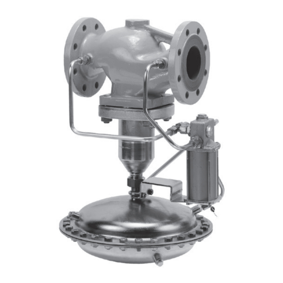
- Page 1 EB 2551-2 EN Translation of original instructions Type 33-7 Safety Excess Pressure Valve (SEV) Self-operated Regulators Edition July 2020...
- Page 2 Note on these mounting and operating instructions These mounting and operating instructions assist you in mounting and operating the device safely. The instructions are binding for handling SAMSON devices. The images shown in these instructions are for illustration purposes only. The actual product may vary.
-
Page 3: Table Of Contents
Contents Safety instructions and measures ..............1-1 Notes on possible severe personal injury ............1-4 Notes on possible personal injury ..............1-5 Notes on possible property damage .............1-7 Markings on the device ................2-1 Nameplate ....................2-1 Location of the nameplate ................2-1 Material numbers ..................2-1 Design and principle of operation ...............3-1 3.1 Additional fittings ..................3-3... - Page 4 Replacing the actuator's operating diaphragm ..........9-4 Ordering spare parts and operating supplies ..........9-4 Decommissioning ..................10-1 Removal ....................11-1 11.1 Removing the regulator from the pipeline ............11-1 Repairs ....................12-1 12.1 Returning devices to SAMSON ..............12-1 Disposal ....................13-1 Certificates ....................14-1 Annex......................15-1 15.1 Tightening torques ..................15-1 15.2 Lubricant ....................15-1 15.3...
-
Page 5: Safety Instructions And Measures
Therefore, operators must ensure that the regulator is only used in operating conditions that meet the specifications used for sizing the regulator at the ordering stage. In case operators intend to use the regulator in other applications or conditions than specified, contact SAMSON. SAMSON does not assume any liability for damage resulting from the failure to use the de- vice for its intended purpose or for damage caused by external forces or any other external factors. Î Refer to the technical data and nameplate for limits and fields of application as well as possible uses. - Page 6 Safety instructions and measures Safety features The Type 33-7 Regulator is a safety excess pressure valve (SEV). When relieved of pressure, the regulator is closed by the force of the positioning springs. Personal protective equipment We recommend checking the hazards posed by the process medium being used (e.g. u GESTIS (CLP) hazardous substances database). Depending on the process medium and/ or the activity, the protective equipment required includes: − Protective clothing, safety gloves and eye protection in applications with hot, cold and/or corrosive media − Wear hearing protection when working near the valve − Hard hat − Safety harness when working at height...
- Page 7 Start-up and shutdown procedures fall within the scope of the operator's duties and, as such, are not part of these mounting and operating instructions. SAMSON is unable to make any statements about these procedures since the operative details (e.g. differential pressures and temperatures) vary in each individual case and are only known to the operator.
-
Page 8: Notes On Possible Severe Personal Injury
Safety instructions and measures Referenced documentation The following documents apply in addition to these mounting and operating instructions: − Mounting and operating instructions for Type 2 N/NI Strainer e.g. u EB 1015 − Data sheets for Type 2 N/NI Strainer e.g. u T 1015 − Mounting and operating instructions as well as data sheets for additional fittings (e.g. shut-off valves, pressure gauges etc.). 1.1 Notes on possible severe personal injury DANGER Risk of bursting in pressure equipment. -
Page 9: Notes On Possible Personal Injury
Safety instructions and measures 1.2 Notes on possible personal injury WARNING Risk of personal injury through incorrect operation, use or installation as a result of information on the regulator being illegible. Over time, markings, labels and nameplates on the regulator may become covered with dirt or become illegible in some other way. As a result, hazards may go unno- ticed and the necessary instructions not followed. - Page 10 WARNING Damage to health relating to the REACH regulation. If a SAMSON device contains a substance which is listed as being a substance of very high concern on the candidate list of the REACH regulation, this circumstance is indi- cated on the SAMSON delivery note.
-
Page 11: Notes On Possible Property Damage
Risk of regulator damage due to contamination (e.g. solid particles) in the pipeline. The plant operator is responsible for cleaning the pipelines in the plant. Î Flush the pipelines before start-up. Note SAMSON's After-sales Service can support you concerning lubricant, tightening torques and tools approved by SAMSON. EB 2551-2 EN... - Page 12 EB 2551-2 EN...
-
Page 13: Markings On The Device
2.2 Location of the nameplate 2.3 Material numbers The material designation can be found on the nameplate (7, body material) or you can Location of the contact us (the configuration ID specification nameplate is needed) to find out which material is used. This is specified on the nameplate in the 'MNo' field (3). For more details on the nameplate, see section 2.1. Fig. 2-2: Nameplate of Type 33-7 Regulator EB 2551-2 EN... - Page 14 EB 2551-2 EN...
-
Page 15: Design And Principle Of Operation
Î See Fig. 3-1 same level of the upstream pressure p causing the main valve (1) to be closed by The Type 33-7 Excess Pressure Valve (SEV) the positioning springs (7). consists of the main valve with actuator and the pilot valve attached to it. - Page 16 Pilot valve 10.1 Control line for upstream pressure p Plug stem 8.1 Filter 11 Control line for downstream pressure p Balancing bellows 8.2 Set point springs 12 Control line for control pressure (p Fig. 3-1: Functional diagram of Type 33-7 EB 2551-2 EN...
-
Page 17: Additional Fittings
Any impurities carried along by the process medium may impair the proper functioning of the regulator. We recommend installing a Strainers strainer (e.g. SAMSON Type 2 NI) upstream We recommend installing a SAMSON of the excess pressure valve (u EB 1015). strainer (2) upstream of the valve. It prevents... -
Page 18: Technical Data
(u T 2551). Process medium and scope of application Noise emissions SAMSON is unable to make general state- The Type 33-7 Safety Excess Pressure Valve (SEV) is used to maintain the pressure up- ments about noise emissions. The noise emis- stream of the regulator to an adjusted set sions depend on the regulator version, plant point. - Page 19 380 at the maximum. However, their design and function are identical to those of the typetest- ed valve sizes. Table 3-2: K coefficients and x values · Terms for noise level calculation according to VDMA 24422 (edition 1.89) Valve size coefficient Value at K 1) value 0.40 0.35 0.30 Despite installing a strainer upstream of the regulator, dirt particles may impair the valve shut-off depending on the size of the strainer mesh. On using the SAMSON Type 2 NI Strainer, the maximum leakage rate may correspond to the specified value at K 0.3 due to the clogging up of the valve. This value is then significant on sizing the safety valve or safety excess pressure valve in the plant. EB 2551-2 EN...
- Page 20 Design and principle of operation Table 3-3: Materials · Material number according to DIN EN Valve Pressure rating PN 16 PN 16 · PN 25 PN 16 · PN 25 · PN 40 Cast iron Spheroidal graphite iron Cast steel Body EN-GJL-250 EN-GJS-400-18-LT 1.0619 1) Seat Stainless steel 1.4006 DN 65 to 100 Stainless steel 1.4006 Plug with EPDM seal DN 125 to 250...
- Page 21 Design and principle of operation Dimensional drawings ØD Fig. 3-3: Dimensions EB 2551-2 EN...
- Page 22 EB 2551-2 EN...
-
Page 23: Shipment And On-Site Transport
2. Check the shipment for transportation ing the valve. damage. Report any damage to Î Dispose and recycle the packaging in SAMSON and the forwarding agent accordance with the local regulations. (refer to delivery note). 3. Determine the weight and dimensions of the units to be lifted and transported in order to select the appropriate lifting equipment and lifting accessories. -
Page 24: Transporting And Lifting The Regulator
Shipment and on-site transport 4.3 Transporting and lifting the WARNING regulator Risk of personal injury due to the regulator tipping. Î Observe the regulator's center of gravity. DANGER Î Secure the regulator against tipping over Danger due to suspended loads falling. or turning. -
Page 25: Lifting The Regulator
Shipment and on-site transport 4.3.2 Lifting the regulator whether the regulator flanges are bolted tight. To install a large regulator into the pipeline, 6. Remove slings. use lifting equipment (e.g. crane or forklift) to lift it. Lifting instructions Î Use a hook with safety latch to secure the slings from slipping off the hook during lifting and transporting (see Fig. 4-1). -
Page 26: Storing The Regulator
Î Observe the storage instructions. Î Do not damage the corrosion protection Î Avoid long storage times. (paint, surface coatings). Repair any Î Contact SAMSON in case of different damage immediately. storage conditions or longer storage Î Protect the regulator against moisture periods. and dirt. Store it at a relative humidity of less than 75 %. In damp spaces, prevent... -
Page 27: Installation
Î Contact SAMSON if the mounting posi- tion. tion is not as specified above. Pipeline routing NOTICE... - Page 28 Installation Support or suspension Standard mounting position, Note suspended The plant engineering company is responsi- All versions. ble for selecting and implementing a suitable support or suspension of the installed regula- tor and the pipeline. Depending on the regulator version and mounting position, the valve, actuator and Not permissible! pipeline must be supported or suspended.
-
Page 29: Preparation For Installation
Installation 5.2 Preparation for installation tings have been installed or prepared as necessary before installing the valve (see Before installation, make sure the following the 'Design and principle of operation' conditions are met: section). − The valve is clean. Proceed as follows: − The valve, actuator and all piping are Î... -
Page 30: Final Installation
Installation 5.3 Final installation 5.3.2 Cleaning the pipeline Tested SAMSON regulators are delivered as We recommend additionally flushing the assembled units. The activities listed below pipeline without the installed regulator be- are necessary for installation and before fore start-up. In this case, install a suitable start-up of the regulator. -
Page 31: Testing The Regulator
Flying projectile fragments or the re- gloves. lease of process medium under pressure can cause serious injury or even death. SAMSON regulators are delivered ready for Before working on the regulator: use. To test the regulator functioning before Î Depressurize all plant sections concerned start-up or putting back the regulator into and the regulator. -
Page 32: Leak Test
The leak test must comply with the The plant operator is responsible for requirements of the national and internation- performing the pressure test. SAMSON's al standards that apply at the site of installa- After-sales Service can support you to plan tion. -
Page 33: Insulation
Installation 5.5 Insulation To insulate cold systems, we recommend first filling the plant and carefully rinsing it. The regulator must not yet be insulated at this stage. 1. Start up the plant and adjust the set point (see the 'Start-up' section). 2. Shut down the plant again and let it heat up until the condensation water has dried off. - Page 34 EB 2551-2 EN...
-
Page 35: Start-Up
Start-up 6 Start-up DANGER The work described in this section is only to Risk of personal injury due to process be performed by personnel appropriately medium escaping. qualified to carry out such tasks. Î Do not start up the regulator until all parts have been mounted. WARNING Before start-up or putting the valve back into Risk of burn injuries due to hot or cold... -
Page 36: Start-Up And Putting The Device Back Into Operation
Start-up 6.1 Start-up and putting the 6.2 Starting up the plant device back into operation 1. Open the shut-off valves slowly prefera- bly starting from the upstream pressure 1. Depending on the field of application, side. Afterwards, open all the valves on allow the regulator to cool down or the consumer side (downstream of the warm up to reach ambient temperature regulator). -
Page 37: Operation
Operation 7 Operation 7.1 Adjusting the set point Immediately after completing start-up or Î The required upstream pressure is set by placing the regulator back into service (see turning the set point adjuster (9) on the the 'Start-up' section), the regulator is ready pilot valve (8) using an open-end wrench for use. - Page 38 EB 2551-2 EN...
-
Page 39: Malfunctions
Malfunctions 8 Malfunctions 8.1 Troubleshooting Malfunction Possible reasons Recommended action Foreign particles blocking the plug in the Î Contact SAMSON's After-sales Service. main valve or pilot valve Î Observe differential pressure Δp specified in Insufficient differential pressure across the Table 3-1 in the 'Design and principle of regulator operation' section. Upstream pressure exceeds the adjusted Defective operating diaphragm Î Contact SAMSON's After-sales Service. -
Page 40: Emergency Action
Malfunctions 8.2 Emergency action Note Contact SAMSON's After-sales Service for Operators are responsible for emergency ac- malfunctions not listed in the table. tion to be taken in the plant. We recommend removing the regulator from The malfunctions listed in section 8.1 are the pipeline before repairing it. caused by mechanical faults and incorrect In the event of a regulator malfunction: regulator sizing. In the simplest case, the... -
Page 41: Servicing
Risk of regulator damage due to the use of nance or service work. unsuitable tools. Î Only use tools approved by SAMSON (see 'Tools' in Annex). WARNING Risk of burn injuries due to hot or cold com- ponents and pipeline. -
Page 42: Preparing The Valve For Service Work
The regulator was checked by SAMSON before it left the factory. − Clean or replace the filter in the pilot − Certain test results certified by SAMSON valve (see section 9.3.1). lose their validity when the regulator is 9.2 Installing the regulator opened. Such testing includes seat leakage after service work and leak tests. - Page 43 Servicing Removing the filter 1. Put the regulator out of operation (see the 'Decommissioning' section). 2. Unscrew the strainer stopper (13, width across flats 19) including seal (50). 3. Remove the filter (42) and clean it, if nec- essary. Installing the filter 1. Insert new or cleaned filter (42). Strainer stopper 2. Place a new seal (50) on the strainer Filter stopper (13).
-
Page 44: Replacing The Seat And Plug
9.4 Ordering spare parts and plug operating supplies Contact your nearest SAMSON subsidiary NOTICE or SAMSON's After-sales Service for infor- Risk of TÜV approval (based on AGFW mation on spare parts, lubricants and tools. worksheet FW 504) becoming void. Î Consult SAMSON's After-sales Service... -
Page 45: Decommissioning
Decommissioning 10 Decommissioning components and process medium being discharged. The work described in this section is only to Î Do not loosen the control line while the be performed by personnel appropriately valve is pressurized. qualified to carry out such tasks. DANGER WARNING Risk of bursting due to incorrect opening of Risk of hearing loss or deafness due to loud pressurized equipment or components. - Page 46 Decommissioning 1. Close the shut-off valve (1) on the up- stream side of the regulator. 2. Close the shut-off valve (6) on the down- stream side of the regulator. 3. Depressurize the plant. 4. Completely drain the pipelines and valve. 5. If necessary, allow the pipeline and reg- ulator components to cool down or warm up to the ambient temperature.
-
Page 47: Removal
Removal 11 Removal 11.1 Removing the regulator from the pipeline The work described in this section is only to be performed by personnel appropriately 1. Support the regulator to hold it in place qualified to carry out such tasks. when separated from the pipeline (see the 'Shipment and on-site transport' sec- WARNING tion). - Page 48 11-2 EB 2551-2 EN...
-
Page 49: Repairs
Contamination, which can be Î Do not perform any repair work on your downloaded from our website at own. u www.samsongroup.com > Service Î Contact SAMSON's After-sales Service & Support > After-sales Service. for repair work. After checking your registration, we will send you a return merchandise authori- zation (RMA). - Page 50 12-2 EB 2551-2 EN...
-
Page 51: Disposal
Disposal 13 Disposal Î Observe local, national and internation- al refuse regulations. Î Do not dispose of components, lubricants and hazardous substances together with your household waste. EB 2551-2 EN 13-1... - Page 52 13-2 EB 2551-2 EN...
-
Page 53: Certificates
Certificates 14 Certificates The EU declaration of conformity is provided on the next page: − EU declaration of conformity in compli- ance with Pressure Equipment Directive 2014/68/EU on page 14-2. EB 2551-2 EN 14-1... - Page 54 Modul D/Module D, Nr./No / N° CE-0062-PED-D-SAM 001-16-DEU-rev-A SAMSON erklärt in alleiniger Verantwortung für folgende Produkte:/For the following products, SAMSON hereby declares under its sole responsibility: Sicherheitsüberströmventil SÜV 2337 (33-7)/Safety Excess Pressure Valve SEV 2337 (33-7) die Konformität mit nachfolgender Anforderung/the conformity with the following requirement.
-
Page 55: Annex
– Strainer stopper (13) SW 19 Control line connection (10, 11, 12) – 15.2 Lubricant SAMSON's After-sales Service can support you concerning lubricants and sealants approved by SAMSON. 15.3 Tools SAMSON's After-sales Service can support you concerning tools approved by SAMSON. -
Page 56: Spare Parts
E-mail address You can reach our after-sales service at aftersalesservice@samsongroup.com. Addresses of SAMSON AG and its subsid- iaries The addresses of SAMSON, its subsidiaries, representatives and service facilities worldwide can be found on our website (u www.samsongroup.com) or in all... - Page 58 EB 2551-2 EN SAMSON AKTIENGESELLSCHAFT Weismüllerstraße 3 · 60314 Frankfurt am Main, Germany Phone: +49 69 4009-0 · Fax: +49 69 4009-1507 samson@samson.de · www.samson.de...
Need help?
Do you have a question about the 33-7 and is the answer not in the manual?
Questions and answers