
Subscribe to Our Youtube Channel
Related Manuals for McQuay MWMX 010FR


Summary of Contents for McQuay MWMX 010FR
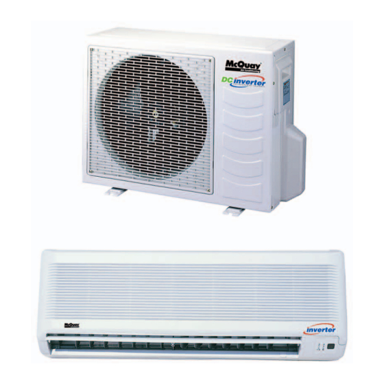
- Page 1 MWMX - 2005 DC Inverter Wall Mounted Models: MWMX 010FR MWMX 015FR REGISTERED ISO 9002 ©2004 McQuay International +1 (800) 432-1342 www.mcquay.com...
-
Page 2: Table Of Contents
"McQuay" is a registered trademark of McQuay International. All rights reserved throughout the world. c 2005 McQuay International "Bulletin illustrations cover the general appearance of McQuay International products at the time of publication and we reserve the right to make changes in design and construction at any time without notice."... -
Page 3: Features
The traditional conventional air conditioners repeat “the start” and “the stop” during the thermostat cycle off and cause the unstable of room temperature. Incorporating fuzzy logic control into the McQuay Inverter design enables greater flexibility in handling the system control. -
Page 4: Nomenclature
Nomenclature Model Type R : heatpump Omitted if Cooling Series F : F series Capacity 010 : 10,000 Btu/h System X : DC Inverter Model Name WM : Wall Mounted Brand M : McQuay... -
Page 5: Specifications
Specif Specif tions MODEL INDOOR UNIT MWMX 010FR MWMX 015FR OUTDOOR UNIT M5LCX 010CR M5LCX 015CR 2,784 (1,084 - 3,516) 3,516 (1,084 - 3,780) NOMINAL COOLING CAPACITY 9,500 (3,700 - 12,000) 12,000 (3,700 - 15,000) -
Page 6: Operating Range
Operating Range Ensure the operating temperature is in allowable range. Cooling only Cooling Caution : The use of your air conditioner outside the range of working temperature and humidity can result in serious failure. Indoor temp. (°CWB) Heatpump Heating Cooling Indoor temp. -
Page 7: Noise Level
500 Hz 1 kHz 2 kHz 4 kHz 8 kHz A (dBA) Criteria H (1250) MWMX 010FR M (1110) L (980) H (1300) MWMX 015FR M (1150) L (1000) Microphone position: MWMX - F/FR - 1m in front of the unit and 0.8m below the vertical centre line of the unit. - Page 8 MMWX 010FR NC CURVE Measured in anechoic room at 1m front and 0.8m below the vertical centre line of the unit MMWX 015FR NC CURVE Measured in anechoic room at 1m front and 0.8m below the vertical centre line of the unit...
-
Page 9: Outlines And Dimensions
Outlines And Dimensions Indoor Unit Model : MWMX 010FR / 015FR Note : Dimension in mm Outdoor Unit Model : M5LCX 010CR / 015CR Note : Dimension in mm... -
Page 10: Refrigeration Cycle Diagram
Refrigeration Cycle Diagram Model : MWMX 010FR / 015FR - M5LCX 010CR / 015CR... -
Page 11: Wiring Diagrams
Wiring Diagrams Model : MWMX 010FR / 015FR Model : M5LCX 010CR / 015CR... -
Page 12: Remote Control Operation Guide
Remote Controller Operation Guide G7 Remote Controller Transmission source Signal transmission indication The source where the signal will be transmitted Blink to confirm the last setting has been send to the unit. Temperature setting To set the desired room On/Off button temperature, press the button to Press once to start the air increase or decrease the set... - Page 13 INDICATOR LIGHTS IR signal receiver Inverted Cooling Unit When all infrared remote control operating signal The table shows the LED indicator lights for the air has been transmitted, the signal receiver on conditioner unit under normal operation and fault indoor unit will make a (beep) sound to confirm conditions.
- Page 14 Inverter Heatpump Unit LED Indicator Lights For Inverter Heatpump Unit Cool / Dry Stand-by / Fan Heat Timer LED Display The LED in indoor and outdoor unit indicate operation modes / faults detected Normal Operation / Fault Condition Action Cool / Dry Heat Stand by Timer...
- Page 15 Compressor Stopped Special Instruction Keep the main power supply ON DO NOT TOUCH ANY OF THE WIRES Open up the outdoor unit’s top panel INSIDE THE UNIT! Count the number of blinks indicated Notice the Green LED on the outdoor P.C. board by the LED Blink Fault Indication...
-
Page 16: Safety Precautions Before Installation
Safety Precautions Before Installation Before Operating, Please Read The Following “Safety Precautions” Carefully. To prevent injury to the user or other people and properties damage, the following instructions must be followed. Incorrect operation due to ignoring of instruction will cause harm or damage, the seriousness is classified by the following indications. - Page 17 Symbol (with white background) denotes item that is PROHIBITED from doing. Symbol (with black background) denotes item that is COMPULSORY to be carried out. Caution Please confirm the following important points when installation • Grounding is necessary It may cause electrical shock if grounding is not perfect. •...
-
Page 18: Special Precautions For R410A
Special Precautions For R410A SPECIAL PRECAUTIONS WHEN DEALING WITH REFRIGERANT R410A UNIT 1) WHAT IS NEW REFRIGERANT R410A? R410A is a new HFC refrigerant which does not damage the ozone layer. The working pressure of this new refrigerant is 1.6 times higher than conventional refrigerant (R22), thus proper installation / servicing is essential. 2) COMPONENTS Mixture weight composition R32(50%) and R125(50%) - Page 19 d) When charging R410A, ensure that only liquid is being withdrawn from the cylinder or can. This is to ensure that only the original composition of R410A is being delivered into the system. The liquid composition can be different from the vapor composition. Invert cylinder Dip-pipe without dip-pipe...
-
Page 20: Installation
Installation Installation Diagram Indoor Unit Outdoor Unit CAUTION : Before installing the unit, ensure that the power supply matches the power requirement of the air conditioner... - Page 21 1) Selection Of Location And Space (A) Indoor Unit Install the fan coil (indoor) unit at a location with the following requirements • Location is suitable for wiring, piping and drainage. • No obstruction of air flow into and out of unit where cooler air can be evenly distributed.(See fig. 1) Ensure that air discharge is not short circuited with air intake.
- Page 22 (B) Outdoor Unit As condensing temperature rises, evaporating temperature rises and cooling capacity drops. In order to achieve maximum cooling capacity, the location selected for outdoor unit should fulfill the following requirements : Install the condensing (outdoor) unit in a way such that hot air distributed by the outdoor condensing unit cannot be drawn in again (as in the case of short circuit of hot discharge air).
- Page 23 2) Drilling Holes And Mounting Installation Plate CAUTION: i) Please check the unit weight for each model. Always ensure that the wall is sufficiently strong to withstand the weight. If not, it is necessary to reinforce the wall with plate, beams or pillars. ii) The unit cannot be directly fixed onto the wall or the likes.
- Page 24 3) Indoor Unit Preparation • • The refrigerant piping can be routed to the unit in 5 Carefully bend the pipes to the required position to direction, by using the cut outs in the unit casing. align with the hole. For right hand and rear side draw (See fig.
- Page 25 5) Water Drainage Piping The indoor drain pipe must be downward gradient for smooth drainage. Avoid situation as shown in figure below. 6) Wiring Electrical Connection • Wiring regulation on wire diameters differ from country to country. Please refer to your LOCAL ELECTRICAL CODES for field wiring rules.
- Page 26 7) Refrigerant Piping Maximum Pipe Length And Maximum Number Of Bends Always choose the shortest path for refrigerant piping and follow the recommendations as tabulated below: Model MWMX 010FR MWMX 015FR Data Max. Length, L (m) Max. Elevation, H (m) Max.
- Page 27 4) After evacuation, unscrew the spindle (diagram B) for the gas to run to indoor unit. Additional Charge The refrigerant gas is charged in the outdoor unit and, if the piping length is less than 7.6m, additional charge of the refrigerant after vacuuming is not necessary. When the piping length is more than 7.6m, please use the table below : Additional charge per meter Model...
-
Page 28: Servicing And Maintenance
vicing vicing And Maintenance And Maintenance Ser vicing vicing vicing And Maintenance And Maintenance And Maintenance CAUTION: After installing or servicing the unit, please ensure that the front panel is secured by the 1 hook underneath the front panel. The unit is designed to give a long life operation with minimum maintenance required. However, it should be regularly checked and the following items should be given due attention. - Page 29 Pre Start Up Maintenance (After Extended Shutdown) Inspect thoroughly and clean indoor and outdoor units. – Clean or replace air filters. – Clean condensate drain line. – Clean clogged indoor and outdoor coils. – Check fan imbalance before operation. – Tighten all wiring connections and panels.
-
Page 30: Troubleshooting
T T T T T r r r r r oub oub leshooting leshooting leshooting leshooting leshooting By means of pressure readings : PRESSURE PROBABLE CAUSE Data Circuit High Side 1. Overcharged with refrigerant. Low Side 2. Non-condensable gases in refrigerant circuit (e.g. oil). 3. - Page 31 The most common causes of air conditioner failure to “start” are : a) Voltage not within +/- 10% of rated voltage. b) Power supply interrupted. c) Control settings improper d) Air Conditioner is disconnected from main power source. e) Fuse blown or circuit breaker off. II) Diagnosis Of Refrigerant Circuit /Application There might be some cases where the unit starts running but does not perform satisfactory, i.e.
-
Page 32: Parts List
P P P P P ar ar ts List ts List ts List ts List ts List Model : MWMX 010FR / 015FR Assy, Mounting Plate A50013032957 10 Fan Bush C/Flow Fan Black A11014029514 Clamp, Piping 10/15F A12014048332 11 Evaporator Coil Assy. - Page 33 Model : M5LCX 010 / 015CR ASSY,PAN BASE SL10/15C A50014057190 ASSY. CONTROL BOX ASSY,CONDENSER COIL 5SL10/15C/10CR M5LCX 010CR A50044061024 M5LCX 010CR A50024065385 M5LCX 015CR A50044061025 M5LCX 015CR A50024058635 10 FAN A03019015339 ASSY. VALVE BRACKET A01014051164 MOTOR ASSY. CAPILLARY TUBE M5LCX 010CR A03039016892 M5LCX 010CR A50024055287...
- Page 34 ©2005 McQuay International +1 (800) 432-1342 www.mcquay.com...
Need help?
Do you have a question about the MWMX 010FR and is the answer not in the manual?
Questions and answers