Table of Contents
Advertisement
Advertisement
Table of Contents

Related Manuals for McQuay M5WM Series


Summary of Contents for McQuay M5WM Series
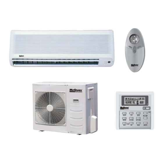
- Page 1 IM-5WMF (SEER13)-0706-McQuay Installation and Maintenance Manual Group: Wall Mounted Part Number: R08019028218 Date: July 2006 M5WM Wall Mounted Split Type Air Conditioner (SEER 13) Indoor Unit Wireless Remote Control (Standard) Wired Wall Control (Optional) Outdoor Unit...
-
Page 2: Table Of Contents
Table of Contents General Information……………………………………………….. 3 Unit Indicator Lights ……………………………....19 Safety Precautions………………………………………. 3 IR Signal Receiver ………………...…………… 19 Unit Dimensions…………………………………………….……... 4 Cooling Only Unit ……………………....19 Indoor Units ……………………………………. ……..4 Heat Pump Unit ………………………....20 Outdoor Units …………………………….…….. ……..4 Special Features …………………………………..….. -
Page 3: General Information
General Information This manual provides installation procedures your conditioner unit operates properly and provides you the service CAUTION it was designed to provide. Special adjustment may be necessary to suit Use copper conductors only. Unit terminals are not local requirements. Before using your air designed to accept other types of conductors. -
Page 4: Unit Dimensions
Unit Dimensions Model: M5WM10F, 10FR – Indoor Unit Model: M5WM15F, 15FR, 20F, 20FR – Indoor Unit Page 4 IM-5WMF(SEER13)-0706... -
Page 5: Indoor Units
Model: M5WM25F, 25FR – Indoor Unit Model: M5LC10C, 10CR, 15C, 15CR – Outdoor Unit Dimension 10C/CR 33-5/8” 24-3/4” 12-7/8” 7/8” 2-5/8” 23-3/4” 5” 15-3/8” 15C/CR 33-5/8” 28-3/4” 12-7/8” 7/8” 2-5/8” 23-3/4” 5” 15-3/8” Dimension 10C/CR 5/8” 14-1/4” 6-1/2” 3” 2-7/8” 15C/CR 5/8”... - Page 6 Model: M5LC20C, 20CR, 25C, 25CR – Outdoor Unit Page 6 IM-5WMF(SEER13)-0706...
-
Page 7: Installation Guidelines
Installation Guidelines Installation Diagram Condensate Disposal of Outdoor Unit (Heat Pump Unit Only) • There are 2 holes on the base of outdoor unit Room Cabinet for condensed water to flow out. Insert the Indoor Unit drain elbow to one of the holes. •... -
Page 8: Piping
Piping Mounting Plate Installation The refrigerant piping can enter the indoor unit at several The mounting plate ships attached to the back of the different locations. Use the knock outs provided in the room indoor unit. To detach for mounting on wall, remove cabinet. -
Page 9: Installing Unit On Mounting Plate
Drain Hose Installation Installing Unit on Mounting Plate The condensate drain hose (20” long) come factory Hook the indoor unit onto the upper portion of the mounting attached to the indoor unit. It is gravity flow. Avoid plate (engage the two hooks at the rear top of the indoor situations that could restrict drainage. -
Page 10: Refrigerant Tubing
Figure 11. Cutting and Flaring Tube Refrigerant Tubing Tubing Length & Elevation Copper tubing to connect the indoor and outdoor units is supplied by others or it can be ordered from the factory. See Table 1 for requirements. Cover both tubes individually with 3/8”... -
Page 11: Electrical Connections
Electrical Connections Figure 14. Terminal Block and wire Clamp WARNING Improper installation can cause severe personal injury or death. Wiring must be done by a qualified electrician in compliance with local codes. Model 10F, 10FR, 15F and 15FR are using two separate power supply. -
Page 12: Heat Pump Unit
Figure 16. Cooling Only Size 20 & 25 Figure 17. Heat Pump Unit Size 20 & 25 Indoor Unit Outdoor Unit Terminal Block Connecting Wires Terminal Block COMP COMP Outdoor coil sensor, 2 conductor cable, (26 feet long) shipped with the indoor unit. Extend with 22 ga. low voltage wire if not long enough to reach outdoor unit. -
Page 13: Wiring Diagrams
Wiring Diagrams INDOOR UNIT MODEL: M5WM 10F – 15F 115V OUTDOOR UNIT MODEL: M5LC 10C – 15C 208/230V IM-5WMF(SEER13)-0607 Page 13... - Page 14 INDOOR UNIT MODEL :M5WM 20F OUTDOOR UNIT OUTDOOR UNIT MODEL: M5LC 20C MODEL: M5LC 20C – 25C Page 14 IM-5WMF(SEER13)-0706...
- Page 15 INDOOR UNIT MODEL: M5WM 25F OUTDOOR UNIT: MODEL: M5LC 25C Page 15 IM-5WMF(SEER13)-0706...
- Page 16 INDOOR UNIT MODEL: M5WM 10FR – 15FR OUTDOOR UNIT MODEL: M5LC 10CR – 15CR IM-5WMF(SEER13)-0706 Page 16...
- Page 17 INDOOR UNIT MODEL: M5WM 20FR OUTDOOR UNIT MODEL: M5LC 20CR IM-5WMF(SEER13)-0706 Page 17...
- Page 18 INDOOR UNIT MODEL: M5WM 25FR OUTDOOR UNIT: MODEL: M5LC 25CR Page 18 IM-5WMF(SEER13)-0706...
-
Page 19: Vacuuming And Charging
Vacuuming and Charging Purging the Piping and the Indoor Unit Charge Operation Except for the outdoor unit which is pre-charged with This operation must be done by using a gas cylinder refrigerant, the indoor unit and the refrigerant connection and a precise weighing machine. The additional charge pipes must be air-purged because the air containing is topped-up into the outdoor unit using the suction moisture that remains in the refrigerant cycle may cause... -
Page 20: Special Precaution When Dealing With R410A Unit
Special Precautions When Unit Indicator Lights IR Signal Receiver Dealing With R410A Unit When an infrared remote control operating signal is R410A is a new HFC refrigerant which does not damage transmitted, the signal receiver on the indoor unit beeps to the ozone layer. -
Page 21: Heat Pump Unit
Heat Pump Unit Table 7 shows the LED indicator lights for the heat pump unit under normal operation and fault conditions. The LED indicator lights are located at the bottom right side of the indoor unit. The heat pump units are equipped to maintain selected room temperature by switching automatically to either “cool” or “heat”... -
Page 22: Special Features
Special Features Dry Mode Overheating Protection (Heat Pump Only) • Select this mode when the standard Cool mode does • If the indoor coil temperature exceeds 145ºF because not provide sufficient dehumidification. The compressor of high ambient conditions, dirty air filter, etc., the and indoor low fan will cycle together and will operate compressor will turn off. -
Page 23: Filter Replacement
Figure 25. Installing Filters Low Ambient Kit With this option, the unit can cool down to 32ºF outdoor temperature. (Standard units only cool down to 66ºF). To install, wire the Fan Speed Control Module (FSCM) in the outdoor unit per wiring diagram supplied with the kit. Attach the Outdoor Coil Sensor to the return bend as shown in Figure 26. -
Page 24: Remote Controller Operation Guide
Remote Controller Operation Guide 1) Transmission Source • The source where the signal is transmitted. 2) Signal Transmission Indication • Blinks to confirm the last setting has been transmitted to the unit. 3) “ON/OFF” Button • Press once to start the unit. •... - Page 25 11) Sleep Mode Setting • Press the SLEEP button will activate the sleep mode function. • This is an energy saving option. When the unit is operating under cooling mode, the set temperature is increased by 0.5ºC after the first half an hour, another 0.5ºC after the second half an hour and 1ºC after the following 1 hour. This function will prevent excessive cooling during summer season.
-
Page 26: Service And Maintenance
Service and Maintenance Troubleshooting CAUTION If any malfunction of the unit is noted, immediately switch off the power supply. Check the following chart for possible causes/treatments. Disconnect electrical power supply before performing service, maintenance trouble persists, please call your local troubleshooting. - Page 27 This document contains the most current product information as of this printing. The manufacturer reserves the right to revise any of the specification and design contain herein at any time without prior notification.
Need help?
Do you have a question about the M5WM Series and is the answer not in the manual?
Questions and answers