Chapters
Table of Contents

Related Manuals for McQuay CE 10C


Summary of Contents for McQuay CE 10C
- Page 1 INSTALLATION MANUAL IM-CEC-0501-McQuay Group: CEILING EXPOSED Part Number: A08019025467 Date: MAY 2001 CEILING/FLOOR EXPOSED CONVERTIBLE SPLIT TYPE AIR CONDITIONER © 2001 McQuay International...
- Page 3 OUTLINE AND DIMENSIONS Indoor Unit (CE - C Series) All dimensions are in mm Model 1050 1203 1130 1180 1050 1203 1130 1180 1050 1203 1130 1180 1400 1553 1480 1530 1750 1903 1830 1880 1750 1903 1830 1880 1750 1903 1830 1880...
- Page 4 SL 30 / 40 / 50 / 60 / 61 C / CR 141,5 141,5 746,5 400,0 40,0 320,0 40,0 1030,0 50,0 85,0 ! Caution Sharp edges and coil surfaces are potential locations which may cause injury hazards. Avoid from being in contact with these places. ! Avertissement Les bords coupants et les surfaces du refroidisseur tuulaire présentent un risque de blessure.
-
Page 5: Installation Manual
CEILING/FLOOR EXPOSED CONVERTIBLE SPLIT TYPE AIR CONDITIONER MODEL COOLING UNIT HEAT PUMP CE 10C / MCM 010C CE 10CR / MCM 010CR SL 10B / MLC 010B SL 10BR / MLC 010BR CE 15C / MCM 015C CE 15CR / MCM 015CR... -
Page 6: Table Of Contents
CONTENTS - Outline And Dimensions page i-ii - Safety Precautions page 2 - Air Conditioner Parts Description page 3 - Installation Of The Indoor Unit page 3 - Installation Of The Outdoor Unit page 4 - Refrigerant Piping page 5 - Electrical Wiring Connection page 6 - Vacuuming And Charging Method... -
Page 7: Air Conditioner Parts Description
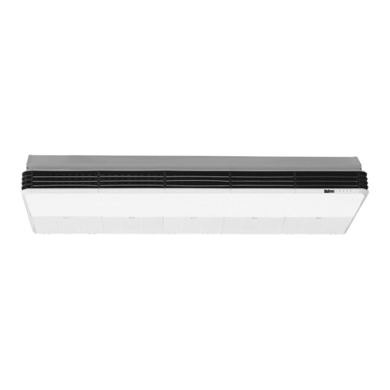
AIR CONDITIONER PARTS DESCRIPTION Indoor Unit Air Discharge Louver Air Discharge Grille Indicator Lights Air Intake Grille Signal Receiver Air Filters (Inside Air Intake Grille) Refrigerant Piping Air Intake Air Intake Air Discharge Nozzle Outdoor Unit Fig. A INSTALLATION OF THE INDOOR UNIT Preliminary Site Survey 5mm (Min.) •... -
Page 8: Installation Of The Outdoor Unit
INSTALLATION OF THE OUTDOOR UNIT • Install the outdoor condensing unit in such a way that • The location must be well-ventilated, so that the unit the hot air distributed cannot be drawn in again (as in can draw in and distribute plenty of air thus lowering the case of short circuit of hot discharge air). -
Page 9: Refrigerant Piping
! Caution If the outdoor condensing unit is operated in an atmosphere containing oils (including machine oils), salt (coastal area), sulfide gas (nearby hot spring or oil refinery plant), such substances may lead to failure of the unit. REFRIGERANT PIPING Maximum Pipe Length And Maximum Number Of Bends If the pipe length is too long, both the capacity and the Therefore, always select the shortest path for the piping... -
Page 10: Electrical Wiring Connection
12.70 5/8" 15.88 3/4" 19.05 Spanar Torque Wrench ELECTRICAL WIRING CONNECTION Electrical Wiring Connection For CE Series 10~25C Indoor Unit CE 10C CE 15C CE 18C CE 20C CE 25C Outdoor Unit SL 10B SL 15B SL 18B SL 20B SL 25B 220V –... - Page 11 CE 30C COMP Interconnection Cable COMP Terminal Strip Indoor Unit Terminal Strip Outdoor Unit The electrical power must be provided with Power Supply protection devices (circuit breaker or fuse) with Cable double pole separation system (phase + neutral) with minimum contact gap of 3mm. Electrical Wiring Connection For CE Series 40 ~ 62C Indoor Unit CE 40C...
- Page 12 CE 30CR Outdoor Coil Sensor Terminal Interconnection Cable Strip COMP Indoor Terminal Strip COMP Unit Outdoor Unit The electrical power must be provided with Power Supply protection devices (circuit breaker or fuse) Cable with double pole separation system (phase + neutral) with minimum contact gap of 3mm.
-
Page 13: Vacuuming And Charging Method
CE 40/50/61/62 CR Terminal Strip Interconnection Cable Terminal Strip Indoor COMP Outdoor Unit Unit COMP The electrical power must be provided with Power Supply protection devices (circuit breaker or fuse) Cable with pole separation system, minimum contact gap of 3mm. IMPORTANT: (1) These values are for information only, they should be checked and selected to comply with the local and/ or national codes and regulations. - Page 14 Indoor 27°C/Outdoor 35°C Indoor 32°C/Outdoor 43°C Kg/cm Psig Kg/cm Psig SL 10B 4.5 – 5.6 65.4 – 79.6 5.2 – 6.3 74.0 – 89.6 SL 15B 4.5 – 5.6 65.4 – 79.6 5.2 – 6.3 74.0 – 89.6 SL 18B 4.5 –...
-
Page 15: Additional Charge
Charging Procedure For 2 X 3 Way Valve (See Figure V) 1) Connect the service hose from the manifold gauge to Figure V the charging cylinder. For 2 x 3 way valve • Connect the service hose, which you have disconnected from the vacuum pump, to the valve at the bottom of the cylinder. -
Page 16: Service And Maintenance
SERVICE AND MAINTENANCE Service Parts Period Maintenance Procedures Indoor air filter At least once 1. Remove any dust adhered on the filter by using a vacuum every 2 week. cleaner or wash in lukewarm water (below 40°C) with neutral cleaning detergent. 2. - Page 17 CLIMATISEUR SPLIT CONVERTIBLE MONTAGE APPARENT PLAFOND / SOL MODÉLE FROID SEUL POMPE À CHALEUR CE 10C / MCM 010C CE 10CR / MCM 010CR SL 10B / MLC 010B SL 10BR / MLC 010BR CE 15C / MCM 015C CE 15CR / MCM 015CR...
- Page 18 SOMMAIRE - Contour Et Dimensions page i-ii - Précautions De Sécurité page 2 - Description Du Climatiseur page 3 - Installation De L’unité Intérieure page 3 - Installation De L’unité Extérieure page 4 - Tuyauteries Frigorifiques page 5 - Raccordement Électrique page 6 - Procedure De Tirage Au Vide Et De Charge page 9...
-
Page 19: Description Du Climatiseur
DESCRIPTION DU CLIMATISEUR Unite Interieure Conduit De Ventilation Grilles De Ventilation Grilles De Reprise D'air Leds De Visualisation Récerteur De Signal Filltre À Air (Sous La Grille De Reprise A'air) Tuyauteries Frigorifiques Reprise D'air Reprise D'air Ventilateur Unite Exterieure Fig. A INSTALLATION DE L'UNITE INTERIEURE Etude Preliminaire Du Site •... -
Page 20: Installation De L'unité Extérieure
INSTALLATION DE L'UNITE EXTERIEURE • Installer le groupe de condensation extérieur de telle • L'emplacement doit être bien ventilé de façon à ce que manière que l’air chaud qu’il dégage ne puisse être repris l'appareil distribue la totalité de l'air à un niveau de par un autre appareil (interférence d’air chaud). -
Page 21: Tuyauteries Frigorifiques
! Avertissement Si le groupe de condensation extérieur fonctionne dans une atmosphère chargée de vapeurs d’huile (y compris huiles de machine) de sel (région côtière) ou de souffre (près d’une source chaude ou d’une raffinerie), ces substances risquent de causer le dysfonctionnement de l’appareil. TUYAUTERIES FRIGORIFIQUES Longueur Maxi Des Tuyauteries Et Nombre Maxi De Coudes Une tuyauterie trop longue va diminuer à... -
Page 22: Raccordement Électrique
12,70 5/8" 15,88 3/4" 19,05 Clef Dynamométrique Clef D'immobilisation RACCORDEMENT ELECTRIQUE Raccordement Électrique Des Modeles CE 10~25C Unite Interieure CE 10C CE 15C CE 18C CE 20C CE 25C Unite Exterieure SL 10B SL 15B SL 18B SL 20B SL 25B Tension d'alimentation (2) 220V –... - Page 23 CE 30C COMP Câble De Liaison COMP Bornier De L'unité Intérieure Bornier De L'unité Extérieure Cordon L'alimentation doit être munie d'un dispositif de pro- Electrique tection (disjoncteur ou fusible) ayant un système de séparation omnipolaire (phase + neutre) avec une distance d'ouverture des contacts d'au moins 3mm.
- Page 24 CE 30CR Sonde De L’unite Exterieure Bornier De Bornier De Câble De Liaison L'unité L'unité COMP Intérieure Extérieure COMP L'alimentation doit être munie d'un dispositif de protection (disjoncteur ou fusible) ayant un Cordon système de séparation omnipolaire (phase + Electrique neutre) avec une distance d'ouverture des contacts d'au moins 3mm.
-
Page 25: Procedure De Tirage Au Vide Et De Charge
CE 40/50/61/62 CR Câble De Liaison Bornier De Bornier De COMP L'unité Extérieure L'unité Intérieure COMP L'alimentation doit être munie d'un dispositif de protection (disjoncteur ou Cordon fusible) ayant un système de séparation Electrique omnipolaire avec une distance d'ouverture des contacts d'au moins 3mm. IMPORTANT: (1) Ces valeurs sont données à... - Page 26 Intérieur 27˚C/Extérieur 35˚C Intérieur 32˚C/Extérieur 43˚C Kg/cm Psig Kg/cm Psig SL 10B 4,5 – 5,6 65,4 – 79,6 5,2 – 6,3 74,0 – 89,6 SL 15B 4,5 – 5,6 65,4 – 79,6 5,2 – 6,3 74,0 – 89,6 SL 18B 4,5 –...
-
Page 27: Charge Additionnelle
Procedure De Charge Pour 2 Robinets à 3 Voies (Voir La Figure V) 1) Connecter la prise centrale de pression du manifold à la Figure V-2 vanne située en bas du cylindre de charge . Pour 2 robinets à 3 voies •... -
Page 28: Entretien Et Maintenance
ENTRETIEN ET MAINTENANCE Pieces A Entretenir Procédure D’entretein Périodicité Filtre à air intérieur 1. Enlever la poussière du filtre à l’aide d’un aspirateur ou en Au moins une fois lavant le filtre à l’eau tiède (moins de 40°C) avec un détergent toutes les 2 neutre. - Page 29 DOPPELFUNKTION SPLIT-SYSTEM MODELL WÄRMEPUMPE KÜHLFUNKTION CE 10CR / MCM 010CR CE 10C / MCM 010C SL 10BR / MLC 010BR SL 10B / MLC 010B CE 15CR / MCM 015CR CE 15C / MCM 015C SL 15BR / MLC 015BR...
- Page 30 INHALT - Auslegung Und Admessung seite i-ii - Vorsichtmaßnahmen seite 2 - Beschreibung Der Klimageräteteile seite 3 - Installation Des Innengerätes seite 3 - Installation Des Außengerätes seite 4 - Kühlmittelleitung seite 5 - Kabelanschluß seite 6 - Vakuum-U. Lademethode seite 9 - Gesamttest seite 11...
-
Page 31: Beschreibung Der Klimageräteteile
BESCHREIBUNG DER KLIMAGERÄTE-TEILE Innen Gerät Abluftaufsatz Abluftgitter Lufteinlassgitter Leuchtanzeige Ir-empfänger Luftfilter (Hinter Lufteinlassgitter) Kältemittelleitung Lufteinlass Lufteinlass Luftauslassdüse Außengerätes Abb. A INSTALLATION DES INNEN GERÄTES Vorbereitende Massnahmen 5mm (Min.) • Stromversorgung und Installation hat in Übereinstimmung mit den landesspezifischen Vorschriften zu erfolgen. •... -
Page 32: Installation Des Außengerätes
INSTALLATION DES AUßENGERÄTES • Der Montageort ist ausreichend zu belüften, so daß das • Das Außengerät mit dem Kondensator ist so zu Gerät in vollem Umfang die Luft ansaugen und verteilen installieren, daß die abgeführte Warmluft nicht wieder kann, um die Temperatur abzusenken. einströmen kann (Interferenz). -
Page 33: Kühlmittelleitung
! Vorsicht Der Betrieb des Kondensatorgerätes in einer stark ölhaltigen Luft (auch von Maschinenöl), salzhaltigen Luft (in Küstengegenden) oder schwefelhaltigen Luft (in der Nähe von heißen Quellen oder einer Raffinerie) kann zu Störungen im Gerät führen. KÜHLMITTELLEITUNG Maximalle Rohrlänge Und Anzahlan Bögen Daher sollte stets der kürzeste Leitungsweg gewählt werden, unter Beachtung der Empfehlungen in der Tabelle. - Page 34 1/2" 12,70 5/8" 15,88 3/4" 19,05 Drehmoment- Anzugsschlüssel Schlüssel KABELANSCHLUß E-Verkabelung CE Modellreihen 10~25C Innen Gerät CE 10C CE 15C CE 18C CE 20C CE 25C Aussen Gerät SL 10B SL 15B SL 18B SL 20B SL 25B Spannungsbereich (2) 220V –...
- Page 35 CE 30C COMP Verbindungskabel COMP Innen Gerät- Klemmenblock Außen Gerät- Klemmenblock Die Stromversorgung muß mit Schutzeinrichtungen Anschluss-Kabel ausgestattet sein (Leitungsunterbrecher oder Sicherung). Vorzusehen ist ein 2-Pol-Schutzschalter (Phase +Nulleiter) mit einem Mindestkontaktabstand von 3mm. E-Verkabelung CE Modellreihen 40~62C Innen Gerät CE 40C CE 50C CE 61C/CE 62C Aussen Gerät...
- Page 36 CE 30CR Außenraum-Sensor Innen Gerät- Verbindungskabel Außen Gerät- COMP Klemmenblock Klemmenblock COMP Die Stromversorgung muß mit Schutzeinrichtungen ausgestattet sein (Leitungsunterbrecher oder Sicherung). Anschluss-Kabel Vorzusehen ist ein 2-Pol-Schutzschalter (Phase +Nulleiter) mit einem Mindestkontaktabstand von 3mm. Innen Gerät CE 30CR Aussen Gerät SL 30CR Spannungsbereich (2) 220V –...
-
Page 37: Vakuum-U. Lademethode
CE 40/50/61/62 CR Verbindungskabel Innen Gerät- COMP Klemmenblock COMP Außen Gerät- Klemmenblock Die Stromversorgung muß mit Schutzeinrichtungen ausgestattet sein (Leitungsunterbrecher oder Sicherung). Vorzusehen ist ein 2-Pol-Schutzschalter Anschluss-Kabel (Phase +Nulleiter) mit einem Mindestkontaktabstand von 3mm. WICHTIG: (1) Die angegeben Werte sind lediglich Richtwerte. Sie sind zu überprüfen und ggf. den örtlichen und/ oderlandesspezifischen Vorschriften und Bestimmungen anzugleichen. - Page 38 Innen 27˚C/Außen 35˚C Innen 32˚C/Außen 43˚C Kg/cm Psig Kg/cm Psig SL 10B 4,5 – 5,6 65,4 – 79,6 5,2 – 6,3 74,0 – 89,6 SL 15B 4,5 – 5,6 65,4 – 79,6 5,2 – 6,3 74,0 – 89,6 SL 18B 4,5 –...
-
Page 39: Gesamttest
Füllverfahren Für 2 x 3-Wege-Ventile (Siehe Abb. V) 1) Wartungsschlauch des Verteiler-Manometers am Abb. V Füllbehälter anschließen. Für 2 x 3 -Wege-Ventile • Den von der Vakuumpumpe abgenommenen Wartungsschlauch am Bodenventil des Füllbehälters Innen Gerät Aussen Gerät anschließen. Flüssigselte • Falls ein Gasbehälter verwendet wird, eine Waage Abblas hinzuziehen und den Behälter umdrehen, sodaß... -
Page 40: Instandhaltung & Wartung
INSTANDHALTUNG & WARTUNG Wartungsteile Wartungsverfahren Intervall Luftfilter Innengerät 1. Luftfilter mit Staubsauger absaugen oder in lauwarmem Mindestens alle 2 Wasser (unter 40°C) mit neutraler Seife auswaschen. Wochen. 2. Sorgfältig ausspülen und vor dem Wiedereinsetzen trocknen. Ggf. häufiger. 3. Weder Benzin, noch Verdünner oder sonstige Chemikalien zum Reinigen verwenden. - Page 41 MONTAGGIO A SOFFITTO O A PAVIMENTO MODELLO RISCALDAMENTO RAFFREDDAMENTO CE 10CR / MCM 010CR CE 10C / MCM 010C SL 10B / MLC 010B SL 10BR / MLC 010BR CE 15C / MCM 015C CE 15CR / MCM 015CR SL 15B / MLC 015B...
- Page 42 SOMMARIO - Disegni E Dimensioni pag. i-ii - Norme Di Sicurezza pag. 2 - Descrizione Dei Componenti pag. 3 - Installazione Dell’unità Interna pag. 3 - Installazione Dell’unità Esterna pag. 4 - Condotti Del Refrigerante pag. 5 - Allacciamenti Elettrici pag.
- Page 43 DESCRIZIONE DEI COMPONENTI Unità Interna Feritoria Di Ventilazione Griglia Di Ventilazione Spie Luminose Griglia Dell'entrata Rejilla De Aire De Retorno Filtri Dell'aria (All'interno Della Griglia Condotti Del Refrigerante D'ingresso Dell'aria) Ingresso Dell'aria Ingresso Dell'aria Effusore Della Ventola Di Aerazione Unità Esterna Fig.
- Page 44 INSTALLAZIONE DELL’UNITÀ ESTERNA • Il luogo prescelto per l’installazione deve essere ben • Installare l’unità esterna di condensazione in modo che ventilato in modo che l’unità possa aspirare e distribuire l’aria calda di emissione non possa essere catturata in una grande quantità d’aria riducendone così la immissione (come avverebbe se la circolazione dei due temperatura.
- Page 45 ! Cautela Se si fa funzionare l’unità di condensazione in un ambiente atmosferico contenente delle particelle d’olio (inclusi oli da macchina), dei sali (nelle zone costiere) o dei gas sulfurei (in prossimità di sorgenti termali o di raffinerie di petrolio), tali sostanze possono provocarne l’avaria.
- Page 46 5/8" 15,88 3/4" 19,05 Chiave Torsiometrica Chiave Fissa ALLACCIAMENTI ELETTRICI Allacciamenti Elettrici Per I Modelli CE 10~25C Unità Interna CE 10C CE 15C CE 18C CE 20C CE 25C Unità Esterna SL 10B SL 15B SL 18B SL 20B SL 25B Voltaggi ammessi (2) 220V –...
- Page 47 CE 30C COMP Cavetto Di Collegamento COMP Morsettiera Dell’unità Interna Morsettiera Dell’unità Esterna Cavo Di L’impianto elettrico deve essere munito di Alimentazione Di Corrente dispositivi di protezione (interruttore di sicurezza o fusibile) con sistema di separazione a doppia polarità (fase+neutro) aventi una distanza dai contatti di almeno 3mm.
- Page 48 Sensore Serpentino Esterna CE 30CR Cavetto Di Collegamento Morsettiera COMP Morsettiera Dell’unità Dell’unità COMP Esterna Interna L’impianto elettrico deve essere munito di dispositivi di protezione (interruttore di sicurezza Cavo Di Alimentazione Di o fusibile) con sistema di separazione a doppia Corrente polarità...
- Page 49 CE 40/50/61/62 CR Cavetto Di Collegamento Morsettiera COMP Morsettiera Dell’unità COMP Dell’unità Interna Esterna L’impianto elettrico deve essere munito di dispositivi di protezione (interruttore di Cavo Di sicurezza o fusibile) con sistema di Alimentazione Di Corrente separazione a polarità aventi una distanza dai contatti di almeno 3mm.
- Page 50 Interna 27ºC/Esterna 35ºC Interna 32ºC/Esterna 43ºC Kg/cm Psig Kg/cm Psig SL 10B 4,5 – 5,6 65,4 – 79,6 5,2 – 6,3 74,0 – 89,6 SL 15B 4,5 – 5,6 65,4 – 79,6 5,2 – 6,3 74,0 – 89,6 SL 18B 4,5 –...
- Page 51 Procedura Di Ricarica Per Modelli A Valvole A 2 x 3 Vie (Vedere Fig. V) 1) Collegare il tubo di servizio dell’indicatore di livello Fig. V del collettore al cilindro di ricarica. Valvole a 2 x 3 vie • Staccare il tubo dalla pompa di estrazione e collegarlo Unità...
- Page 52 PULIZIA E MANUTENZIONE Componenti Procedure Di Manutenzione Frequenza Filtro dell'aria interno 1. Togliere la polvere dal filtro usando un'aspirapolvere o lavarlo Almeno due volte in acqua tiepida (sotto ai 40˚C) con detersivo neutro. al mese. 2. Sciacquare bene e asciugare il filtro prima di rimetterlo Più...
- Page 53 CLIMATIZADOR DIVIDIDO EN COMPONENTES, VESIBLE Y CONVERTIBLE TECHO/SUELO MODELO CALENTADOR ENFRIAMIENTO CE 10C / MCM 010C CE 10CR / MCM 010CR SL 10B / MLC 010B SL 10BR / MLC 010BR CE 15C / MCM 015C CE 15CR / MCM 015CR...
- Page 54 ÍNDICE - Esquema Y Dimensiones pagina i-ii - Precautiones De Seguridad pagina 2 - Descripción De Las Partes Del Equipo De Aire Acondicionado pagina 3 - Instalación De La Unidad Interior pagina 3 - Instalación De La Unidad Exterior pagina 4 - Tubería De Refrigerante pagina 5 - Conexión Del Cableado Eléctrico...
- Page 55 DESCRIPCIÓN DE LAS PARTES DEL EQUIPO DE AIRE ACONDICIONADO Unidad Interior Persiana De Descarga De Aire Rejilla De Descarga De Aire Rejilla De Entrada De Aire Luces Indicadoras Receptor De Señal Filtros Del Aire (Dentro De La Rejilla De Entrada De Aire) Tubería De Refrigerante Entrada De Aire Entrada De Aire...
- Page 56 INSTALACIÓN DE LA UNIDAD DE EXTERIOR • El emplazamiento debe estar bien ventilado, de manera • Instalar la unidad de condensación (de exterior) de tal que la unidad pueda aspirar y distribuir aire en manera que el aire caliente distribuido por la unidad de abundancia -disminuyendo, por consiguiente, la condensación de exterior no pueda ser aspirado temperatura.
- Page 57 ! Cuidado Si la unidad exterior de condensación es utilizada en una atmósfera que contenga aceites (aceites de máquinas incluidos), sal (zona costera) o gases sulfurosos (en las proximidades de aguas termales o de refinerías de petróleo), dichas substancias pueden producir la avería de la unidad. TUBERÍA DE REFRIGERANTE Longitud Maxima De La Tubería Y Numero Maximo De Curvas Si la tubería es demasiado larga, tanto la capacidad como...
- Page 58 Llave Dinamométrica 3/4" 19,05 Llave De Tuerca CONEXIÓN DEL CABLEADO ELÉCTRICO Conexión Del Cableado Eléctrico Para La Series CE 10~25C Unidad De Interior CE 10C CE 15C CE 18C CE 20C CE 25C Unidad De Exterior SL 10B SL 15B...
- Page 59 CE 30C COMP Cable De Interconexión COMP Regleta De Terminales Unidad De Regleta De Interior Terminales Unidad De Exterior La fuente de alimentación debe poseer El Cabel Del dispositivos de protección (disyuntor o fusible) Enchuffe con un sistema de separación bipolar (fase + neutro) con una separación entre contactos minima de 3mm.
- Page 60 Sensor Del Serpentín De Exterior CE 30CR Cable De Interconexión Regleta De Regleta De COMP Terminales Unidad Terminales COMP De Exterior Unidad De Interior La fuente de alimentación debe poseer dispositivos de protección (disyuntor o fusible) con un sistema de separación bipolar (fase + El Cabel Del Enchuffe neutro) con una separación entre contactos minima de 3mm.
- Page 61 CE 40/50/61/62 CR Regleta De Cable De Interconexión Terminales Regleta De COMP Unidad De Terminales COMP Exterior Unidad De Interior La fuente de alimentación debe poseer dispositivos de protección (disyuntor o fusible) con un sistema de separación bipolar (fase + neutro) con una El Cabel Del Enchuffe separación entre contactos minima de 3mm.
- Page 62 Interior 27˚C/Exterior 35˚C Interior 32˚C/Exterior 43˚C Kg/cm Psig Kg/cm Psig SL 10B 4,5 – 5,6 65,4 – 79,6 5,2 – 6,3 74,0 – 89,6 SL 15B 4,5 – 5,6 65,4 – 79,6 5,2 – 6,3 74,0 – 89,6 SL 18B 4,5 –...
- Page 63 Procidimiento De Carga Para Una Válvula 2 X 3 VÍAS (Véase La Fig. V) 1) Conectar la manguera de servicio del manómetro del Fig. V múltiple al cilindro de carga. Para una válvula de 2x3 vías • Conecte la manguera de servicio, que ha Lado De Unidad De Exterior Unidad De Interior...
- Page 64 REPARACIONES Y MANTENIMIENTO Componentes Procedimientos Para Su Mantenimiento Precuencia Filtro de aire 1. Elimine el polvo adherido al filtro mediante una aspiradora o Al menos una vez lavándolo en agua templada (a menos de 40°C) con un jabón cada dos semanas. (unidad de interior) neutro.
- Page 65 МOДOЛЬ ОБOГPEBATEЛЬНЫЙ НACOC ОXЛAЖ EHИЯ МOДOЛЬ Д CE 10C / MCM 010C CE 10CR / MCM 010CR SL 10B / MLC 010B SL 10BR / MLC 010BR CE 15C / MCM 015C CE 15CR / MCM 015CR SL 15B / MLC 015B...
- Page 66 СОДЕРЖАНИЕ - Схема И Pазмеры страница i-ii - Меры Предосторожности страница 2 - Описание Частей Kондиционера страница 3 - Установка Kомнатного Блока страница 3 - Установка Hаружного Блока страница 4 - Трубопровод Xладагента страница 5 - Электрическая Cхема Cоединений страница 6 - Операции...
- Page 67 ОПИСАНИЕ ЧАСТЕЙ КОНДИЦИОНЕРА Кoмнaтный Блoк Жaпюзп Выпускa Вoздухa Рeшeткa Выпycкa Вoздyxa Пoкaзaния Рeшeткa Впycкa Вoздyxa Индикaтopoв Дaтцик Сигналoв Вoздyшные Фильтры (Внyтpeнняя Рeшeткa Трубопровод хладогента Впycкa Вoздyxa) Впycк Вoздyxa Впycк Вoздyxa Отвeрcтиe Выпуcка Вoздyxa Наpужмы Блoк Рис.А УСТАНОВКА КОМНАТНОГО БЛОКА Пpедваpитeльныи Оcмoтp Мecтa Уcтaнoвки 5мм...
- Page 68 УСТАНОВКА НАРУЖНОГО БЛОКА • Установите внешний модуль конденсации так, • Место должно быть легкопроветриваемо, так что модуль мог забирать и распространять чтобы горячий воздух не попал обратно в модуль (аналогично ситуации со столкновением большой объем воздуха, таким образом выпуска горячего воздуха с препятствием). понижая...
- Page 69 ! Осторожно Если наружный блок конденсации работает в атмосфере, содержащие масла (включая машинные масла), солей (район побережья), сероводородного газа (вблизи горячего источника или предприятия по производству растительного масла), то эти вещества могут привести к поломке блока. ТРУБОПРОВОД ХЛАДАГЕНТА Мaкcимaльнaя Длинa Тpyбы И Мaкcимaльнoe Чиcлo Сгибoв Если...
- Page 70 5/8" 15,88 3/4" 19,05 Динaмoмeтpичecкии Ключ Гaeчный Ключ ЭЛЕКТРИЧЕСКАЯ СХЕМА СОЕДИНЕНИЙ Элeктpичecкaя Сxeмa Сoeдинeний Для Сepий 10~25С Кoмнaтный Блoк CE 10C CE 15C CE 18C CE 20C CE 25C Нapyжный Блoк SL 10B SL 15B SL 18B SL 20B SL 25B Диапазон...
- Page 71 CE 30C Кaбeль COMP Мeжcoединeния COMP Кoлoдкa Сoeдинитeля Кoмнaтнoгo Блокa Кoлoдкa Сoeдинителя Нapyжнoгo Блoкa Электроснабжение должно обеспечено с приборами защиты (автоматический Шнyр Сeти выключатель или предохранитель) с двухполярной сепарационной системой (фаза + нейтральный) с минимальным расстоянием между клеммами 3мм. Элeктpичecкaя Сxeмa Сoeдинeний Для Сepий 40~62С Кoмнaтный...
- Page 72 Дaтчик Эмeeвикa Нapyжнoгo Блoкa CE 30CR Кoлoдкa Кaбeль Кoлoдкa Сoeдинитeля Мeжcoединeния Сoeдинителя Кoмнaтнoгo COMP Нapyжнoгo Блoкa Блокa COMP Электроснабжение должно обеспечено с приборами защиты (автоматический выключатель или предохранитель) с двухполярной Шнyр Сeти сепарационной системой (фаза + нейтральный) с минимальным расстоянием между клеммами 3мм. Кoмнaтный...
- Page 73 CE 40/50/61/62 CR Кaбeль Кoлoдкa Мeжcoединeния COMP Сoeдинителя Кoлoдкa Нapyжнoгo COMP Сoeдинитeля Блoкa Кoмнaтнoгo Блокa Электроснабжение должно обеспечено с приборами защиты (автоматический выключатель или предохранитель) с двухполярной сепарационной системой (фаза + нейтральный) Шнyр Сeти с минимальным расстоянием между клеммами 3мм. ВАЖНО...
- Page 74 В комнате 27°C/Снаружи 35°C В комнате 32°C/Снаружи 43°C Кг/см Фсдг Кг/см Фсдг SL 10B 4,5 – 5,6 65,4 – 79,6 5,2 – 6,3 74,0 – 89,6 SL 15B 4,5 – 5,6 65,4 – 79,6 5,2 – 6,3 74,0 – 89,6 SL 18B 4,5 –...
- Page 75 Пpoцeдуpы Зaпpaвки Для 2 x 3 Хoдoвoгo Клaпaнa (Смoтpитe Риcyнoк Ц) 1) Соедините вспомогательный шланг Риcyнoк Ц распределительной коробки к заправочному цилиндру. Для 2 x 3 ходового клапана • Соедините вспомогательный шланг, ранее отсоединенный от вакуумного насоса, к клапану Стopoнa Нapyжный...
- Page 76 СЕРВИС И ТЕХНИЧЕСКОЕ ОБСЛУЖИВАНИЕ Узлы Обcлyживaния Пpoцeдypы Тexничecкoгo Обcлyживaния Вpeмя Комнатный Не реже 2 раз в 1. Очистите от пыли фильтр пылесосом или вымойте его в теплой воздушный фильтр неделю. воде (ниже 40˚С) нейтральным моющим средством. Чаще при 2. Хорошо прополоскайте и высушите фильтр перед установкой необходимости.
- Page 78 • In the event that there is any conflict in the interpretation of this manual and any translation of the same in any language, the English version of this manual shall prevail. • The manufacturer reserves the right to revise any of the specification and design contain herein at any time without prior notification.
- Page 79 VOÂd² « VO²Â IM-CEC-0501-McQuay nI ë ·uAJÄ ∫ WŽuL−Ä ∫ ¡e'« rÁ— A08019025467 ∫ a¹—Uð MAY 2001 q¹uײK qÐUI «Ë qBHM*« ŸuM « sÄ ¡«u¼ WHOJÄ « Ë√Ø÷—_« vKŽ UN³OÂdð sJ1 YO×Ð © 2001 McQuay International...
- Page 81 œUFÐ_«Ë wDOD ²Ã« rÝdë œUFÐ_«Ë wDOD ²Ã« rÝdë œUFÐ_«Ë wDOD ²Ã« rÝdë œUFÐ_«Ë wDOD ²Ã« rÝdë œUFÐ_«Ë wDOD ²Ã« rÝdë CE - C © © © © © q K ð® ∫ WOKš«bë …bŠuë q K ð® ∫ WOKš«bë …bŠuë q K ð®...
- Page 82 SL 30 / 40 / 50 / 60 / 61 C / CR 141,5 141,5 746,5 400,0 40,0 40,0 320,0 1030,0 50,0 85,0 ÆÕËd'« dÞU Ä V³ ð w²Ã«Ë WMÄU lÁ«uÄ w WH²KÄ `DÝ« Ë …œUŠ U UŠ tO³Mð tO³Mð tO³Mð...
- Page 83 ë Ë√ “«dÞ “«dÞ lłd*« “«dÞ CE 10CR / MCM 010CR CE 10C / MCM 010C SL 10BR / MLC 010BR SL 10B / MLC 010B CE 15CR / MCM 015CR CE 15C / MCM 015C SL 15BR / MLC 015BR...
- Page 84 U¹u²;« U¹u²;« U¹u²;« U¹u²;« U¹u²;« ii – i œUFÐ_«Ë wDOD ²Ã« rÝdë ≠ ≤ ÊUÄ_« UÞUO²Š« ≠ ≥ ¡«uNë WHOJÄ ¡«eł« n Ë ≠ ≥ WOKš«bë …bŠuë VOÂdð ≠ ¥ WOł—U)« …bŠuë VOÂdð ≠ µ b¹d³²Ã« VOÐU½√ ≠ ∂ WOzUÐdNJë „öÝô« qO uð ≠ π...
- Page 85 ¡«uNë WHOJÄ ¡«eł« n Ë ¡«uNë WHOJÄ ¡«eł« n Ë ¡«uNë WHOJÄ ¡«eł« n Ë ¡«uNë WHOJÄ ¡«eł« n Ë ¡«uNë WHOJÄ ¡«eł« n Ë WOKš«bë …bŠuë WOKš«bë …bŠuë WOKš«bë …bŠuë WOKš«bë …bŠuë WOKš«bë …bŠuë ¡«uNë m¹dHð oý ¡«uNë m¹dHð WJO³ý ¡«uNë...
- Page 86 WOł—U)« …bŠuë VOÂdð WOł—U)« …bŠuë VOÂdð WOł—U)« …bŠuë VOÂdð WOł—U)« …bŠuë VOÂdð WOł—U)« …bŠuë VOÂdð • • sÄ …bŠuë sJL²ð YO×Ð ¨…bOł W¹uNð «– lÁuÄ YO×Ð WI¹dDÐ WOł—U)« nO¦J²Ã« …bŠË VOÂdð V−¹ iH ¹ Ícë ¡«uNë sÄ …dO³Â WOL l¹“uðË V×Ý …dÄ...
- Page 87 tO³Mð tO³Mð tO³Mð tO³Mð tO³M𠨩WOKŠU ë WIDM*«® `K*« ¨©szUJ*« u¹“ UNML{ sÄ® u¹eë vKŽ Íu²×¹ uł w WOł—U)« nO¦J²Ã« …bŠË qOGAð - «–« Æ…bŠuë qDŽ vë œ«u*« Ác¼ q¦Ä ÍœRð Æ© u¹eë d¹dJð …bŠË Ë« …—U(« lOÐUMOë sÄ »dIÃUЮ bO²¹d³Jë “Už Ë« b¹d³²Ã«...
- Page 88 WK K à WOzUÐdNJë „öÝô« WJ³ý qO uð WK K à WOzUÐdNJë „öÝô« WJ³ý qO uð WK K à WOzUÐdNJë „öÝô« WJ³ý qO uð CE 25C CE 20C CE 18C CE 15C CE 10C WOKš«bë …bŠuë WOKš«bë …bŠuë WOKš«bë …bŠuë WOKš«bë …bŠuë WOKš«bë …bŠuë SL 25B...
- Page 89 CE 30C COMP qO u²Ã« qÐU COMP WO dDë W Ô I ] Aë WOKš«bë …bŠuë WO dDë W Ô I ] Aë WOł—U)« …bŠuë w? z U? Ð d? N ? J ? à « —U? O ? ² ? K à W¹ULŠ qzUÝË dO uð V−¹ —UO²ÃUÐ...
- Page 90 CE 30CR wł—U)« nK*« f ×²Ä qO u²Ã« qÐU COMP WO dDë W Ô I ] Aë WO dDë W Ô I ] Aë COMP WOKš«bë …bŠuë WOł—U)« …bŠuë lÞUÁ® wzUÐdNJë —UO²Kà W¹ULŠ qzUÝË dO uð V−¹ —UO²ÃUÐ œËe²Ã« qÐU ÃËœe? Ä...
- Page 91 CE 40/50/61/62 CR qO u²Ã« qÐU COMP WO dDë W Ô I ] Aë COMP WOKš«bë …bŠuë WO dDë W Ô I ] Aë WOł—U)« …bŠuë —U? ? ? O ? ? ? ² ? ? ? K ? ? ? à W? ? ? ¹ U? ? ? L ? ? ? Š q? ? ? z U? ? ? Ý Ë d? ? O ? ? u? ? ð V? ? − ? ? ¹ Ë«...
- Page 92 ° ° °      °      ¥≥ WOł—U)«Ø ¥≥ WOł—U)«Ø ¥≥ WOł—U)«Ø ≥≤ WOKš«bë …bŠuë ≥≤ WOKš«bë …bŠuë ≥≤ WOKš«bë …bŠuë ¥≥ WOł—U)«Ø ¥≥ WOł—U)«Ø ≥≤ WOKš«bë …bŠuë ≥≤ WOKš«bë …bŠuë ≥µ WOł—U)«Ø ≥µ...
- Page 93 © © © © © rÝ— dE½«® U¼U&« ≥ Ë ≤ ‡Ð ÂULBKà s×Aë ¡«dł« rÝ— dE½«® U¼U&« ≥ Ë ≤ ‡Ð ÂULBKà s×Aë ¡«dł« rÝ— dE½«® U¼U&« ≥ Ë ≤ ‡Ð ÂULBKà s×Aë ¡«dł« rÝ— dE½«® U¼U&« ≥ Ë ≤ ‡Ð ÂULBKà s×Aë ¡«dł« rÝ—...
- Page 94 W½UOBÃ«Ë `OKB²Ã« W½UOBÃ«Ë `OKB²Ã« W½UOBÃ«Ë `OKB²Ã« W½UOBÃ«Ë `OKB²Ã« W½UOBÃ«Ë `OKB²Ã« W½UOBë «¡«dł« W½UOBë «¡«dł« W½UOBë «¡«dł« W½UOBë «¡«dł« W½UOBë «¡«dł« W½UOBë ÂU Á« W½UOBë ÂU Á« W½UOBë ÂU Á« W½UOBë ÂU Á« W½UOBë ÂU Á« …b*« …b*« …b*« …b*« …b*« W MJÄ...
- Page 96 Æ…bzU ë w¼ W¹eOKJ½ô« W Më ÊuJð ¨X½U WGà W¹QÐ UN H½ WLłd²Ã« w ·ö²š« Í«Ë VO²Jë «c¼ dO Hð w ÷—UFð Í« ÀbŠ «–« • Æo³ Ä —UFý≈ ÊËœ sÄ XÁË Í« w UM¼ …œułuÄ UH «uÄ W¹«Ë rOLB²Ã« q¹bFð o×Ð lMB*« kH²×¹ •...
Need help?
Do you have a question about the CE 10C and is the answer not in the manual?
Questions and answers