Advertisement
Table of Contents
- 1 Table of Contents
- 2 Safety Precautions
- 3 Installation Diagram
- 4 Outline and Dimensions
- 5 Installation of the Indoor Unit
- 6 Installation of the Outdoor Unit
- 7 Refrigerant Piping
- 8 Electrical Connection
- 9 Purging the Refrigerant Piping
- 10 Additional Charge
- 11 Overall Checking
- 12 Standard Operating Condition
- 13 Auto Random Re-Start Function
- 14 Service and Maintenance
- 15 Trouble Shooting
- 16 Caution
- Download this manual
This manual provides the procedures of installation to ensure a safe and good standard of operation for the air
conditioner unit.
Special adjustment may be necessary to suit local requirements.
Before using your air conditioner, please read this instruction manual carefully and keep it for future reference.
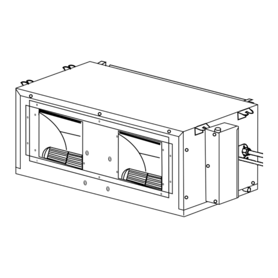
CEILING CONCEALED SPLIT TYPE AIR CONDITIONER
MODEL
COOLING UNIT
CC10C / ACC10C / MCC010C
SL10B / ALC10B / MLC010B
CC15C / ACC15C / MCC015C
SL15B / ALC15B / MLC015B
CC20C / ACC20C / MCC020C
SL20B / ALC20B / MLC020B
CC25C / ACC25C / MCC025C
SL25B / ALC25B / MLC025B
CC30C / ACC30C / MCC030C
SL30C / ALC30C / MLC030C
CC40C / ACC40C / MCC040C
SL40C / ALC40C / MLC040C
CC50C / ACC50C / MCC050C
SL50C / ALC50C / MLC050C
CC60C / ACC60C / MCC060C
SL60C / ALC60C / MLC060C
Part No.: 08019011545
CCC-0700 (01~16) ENG*
INSTALLATION MANUAL
1
HEAT PUMP
CC10CR / ACC10CR / MCC010CR
SL10BR / ALC10BR / MLC010BR
CC15CR / ACC15CR / MCC015CR
SL15BR / ALC15BR / MLC015BR
CC20CR / ACC20CR / MCC020CR
SL20BR / ALC20BR / MLC020BR
CC25CR / ACC25CR / MCC025CR
SL25BR / ALC25BR / MLC025BR
CC30CR / ACC30CR / MCC030CR
SL30CR / ALC30CR / MLC030CR
CC40CR / ACC40CR / MCC040CR
SL40CR / ALC40CR / MLC040CR
CC50CR / ACC50CR / MCC050CR
SL50CR / ALC50CR / MLC050CR
CC60CR / ACC60CR / MCC060CR
SL60CR / ALC60CR / MLC060CR
1-1
2/1/01, 10:41 AM
IM-CCC-0700-1
Advertisement
Table of Contents


Need help?
Do you have a question about the CC10C and is the answer not in the manual?
Questions and answers