Table of Contents
Advertisement
Quick Links
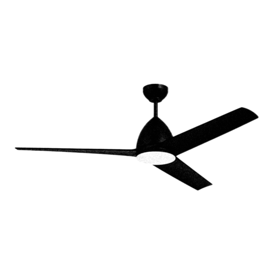
Nitro
Installation Guide
For Model:
NTO54
4007498
APPROVED FOR USE IN
WET LOCATIONS
net weight of fan: 16.20 lb (7.35 kg)
READ THESE INSTRUCTIONS AND
SAVE THEM FOR FUTURE USE
Table of Contents:
Safety Tips. pg. 2
Unpacking Your Fan. pg. 3
Parts Inventory. pg. 3
Installation Preparation. pg. 4
Hanging Bracket Installation. pg. 4
Fan Assembly. pgs. 5 - 6
Wiring. pg. 7 - 8
Canopy Assembly. pg. 8
Blade Assembly. pg. 8
Assembly. pgs. 10 - 11
Remote/Wall Control Operation. pg. 11
Testing Your Fan. pg. 11
Troubleshooting. pg. 12
Warranty. pg. 12
page 1
PRINTED IN CHINA
Advertisement
Table of Contents

Related Manuals for Craftmade Nitro


Summary of Contents for Craftmade Nitro
-
Page 1: Table Of Contents
READ THESE INSTRUCTIONS AND SAVE THEM FOR FUTURE USE Nitro Installation Guide Table of Contents: Safety Tips. pg. 2 Unpacking Your Fan. pg. 3 For Model: Parts Inventory. pg. 3 NTO54 Installation Preparation. pg. 4 Hanging Bracket Installation. pg. 4 Fan Assembly. -
Page 2: Safety Tips
Light kit is dimmable to 10% with the wall control included. Distributed by: Craftmade, 3901 S 20 Avenue, DFW Airport, TX, 75261; 1-800-486-4892 NOTE: The important safety precautions and instructions appearing in the manual are not meant to cover all possible conditions and situations that may occur. -
Page 3: Unpacking Your Fan
1. Unpacking Your Fan. Carefully open the packaging. Remove items from Styrofoam inserts. Remove motor housing and place on carpet or Styrofoam to avoid damage to finish. Do not discard fan carton or Styrofoam inserts should this fan need to be returned for repairs. -
Page 4: Installation Preparation
3. Installation Preparation. blade edge To prevent personal injury and damage, ensure that inches the hanging location allows the blades a clearance of 7 feet (76cm) 7ft. (2.13m) from the floor and 30in. (76cm) from any (2.13m) wall or obstruction. This fan is suitable for room sizes up to 400 square feet (37.2 square meters). -
Page 5: Fan Assembly. Pgs
5. Fan Assembly. stop pin Remove hanging ball from downrod provided by set screw loosening set screw on hanging ball. Remove pin and clip. Lower hanging ball and remove stop pin. Then slide hanging ball off downrod. [Refer to hanging ball diagram 1.] clip Loosen yoke set screws and nut at top of motor... - Page 6 5. Fan Assembly. (cont.) Thread safety cable and wires through hanging ball; then, slide hanging ball over downrod--the top of weatherproof the downrod should be noted as having a set screw hanging hole; use this hole when setting the set screw. Insert ball cover stop pin into top of downrod and raise hanging ball.
-
Page 7: Wiring
6. Wiring. WARNING: Turn off circuit breakers to current white supply wire fixture from breaker panel and be sure switch is turned to the OFF position. ground (green black supply wire or bare) CAUTION: Be sure outlet box is properly grounded and that a ground wire (GREEN or Bare) is present. -
Page 8: Canopy Assembly
6. Wiring. (cont.) Remove existing wall switch. [PLEASE NOTE: Wall and/or handheld remote control must be used for fan to operate. (If you do wall outlet box not wish to use the wall control, please proceed to control Section 7, page 8 to continue with fan installation.)] dimmer To install wall control, remove existing wall switch... -
Page 9: Blade Assembly
8. Blade Assembly. WARNING: To reduce the risk of serious bodily injury, DO NOT use power tools to motor assemble the blades. If screws are housing overtightened, blades may crack and break. Locate and remove 6 blade attachment screws/lock washers on bottom of motor housing. - Page 10 9. Light Kit Assembly (Optional). (cont.) If you wish to USE the light kit, align grooves on shade with nodules on inside of fitter plate and motor housing push up gently on shade. Twist shade to the RIGHT (clockwise) until shade locks into place. Pull down VERY GENTLY on shade to make sure that shade is secure.
-
Page 11: Handheld Remote Control
10. Handheld Remote Control Assembly. (cont.) In order to use wall control as a handheld remote control, wall control dimmer cut each wire on wall control (that was not previously switch used)--use wire cutters to cut off each wire as close to the wire wall control as possible. -
Page 12: Automated Learning Process./Activating Code
11. Automated Learning Process./Activating Code. CAUTION: The wall and/or handheld remote control can be programmed to multiple receivers or fans. If this is not desired, turn wall switch off to any other programmable receiver or fan. Restore electrical power and then, if using wall control, set slider switch on wall control to the ON position. Within 60 seconds of turning on the wall control, press and hold the OFF button on the wall control for 5 seconds (or until light blinks twice or fan blades begin to turn). -
Page 13: Troubleshooting
Troubleshooting. Warranty. WARNING: Failure to disconnect power supply CRAFTMADE LIMITED LIFETIME WARRANTY: CRAFTMADE warrants this fan for use as intended under prior to troubleshooting any wiring issues may the following provision: CRAFTMADE will replace any fan result in serious injury.
Need help?
Do you have a question about the Nitro and is the answer not in the manual?
Questions and answers