Table of Contents
Advertisement
Available languages
Available languages
Quick Links
Nicolas
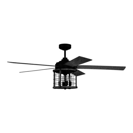
Installation Guide
For Model:
NIC56
net weight of fa
net weight of fan: 23.15 lb (10.5 kg)
Table of Contents:
Safety Tips. pg. 2
Unpacking Your Fan. pg. 3
Parts Inventory. pg. 3
Installation Preparation. pg. 4
Hanging Bracket Installation. pg. 4
Fan Assembly. pgs. 5 - 6
Wiring. pgs. 6 - 7
Canopy Assembly. pg. 7
Blade Assembly. pg. 8
Light Kit Assembly. pgs. 8 - 9
pgs. 9 - 10
Remote/Wall Control Operation. pg. 11
Testing Your Fan. pg. 11
Troubleshooting. pg. 12
Warranty. pg. 12
Parts Replacement. pg. 12
page 1
READ THESE INSTRUCTIONS AND
SAVE THEM FOR FUTURE USE
PRINTED IN CHINA
Advertisement
Table of Contents

Related Manuals for Craftmade Nicolas


Summary of Contents for Craftmade Nicolas
-
Page 1: Table Of Contents
READ THESE INSTRUCTIONS AND SAVE THEM FOR FUTURE USE Nicolas Installation Guide For Model: NIC56 Table of Contents: Safety Tips. pg. 2 Unpacking Your Fan. pg. 3 Parts Inventory. pg. 3 Installation Preparation. pg. 4 Hanging Bracket Installation. pg. 4 Fan Assembly. -
Page 2: Safety Tips
(2) this LED light kit must accept any interference received, including interference that may cause undesired operation. Distributed by: Craftmade, 650 S. Royal Lane, Coppell, TX, 75019; 1-800-486-4892 NOTE: The important safety precautions and instructions appearing in the manual are not meant to cover all possible conditions and situations that may occur. -
Page 3: Unpacking Your Fan
1. Unpacking Your Fan. Carefully open the packaging. Remove items from Styrofoam inserts. Remove motor housing and place on carpet or Styrofoam to avoid damage to finish. Do not discard fan carton or Styrofoam inserts should this fan need to be returned for repairs. Check against parts inventory that all parts have been included. -
Page 4: Installation Preparation
3. Installation Preparation. blade edge To prevent personal injury and damage, ensure that the hanging location allows the blades a inches clearance of 7ft. (2.13m) from the floor and 30in. 7 feet (76cm) (2.13m) (76cm) from any wall or obstruction. This fan is suitable for room sizes up to 400 square feet (37.2 square meters). -
Page 5: Fan Assembly. Pgs
5. Fan Assembly. set screw stop pin Remove hanging ball from downrod provided by loosening set screw on hanging ball. Lower hanging ball and remove stop pin and then slide hanging ball hanging ball [Refer to diagram 1.] off of the downrod. Loosen yoke set screws and nuts at top of motor diagram 1 housing. -
Page 6: Wiring. Pgs
wood ceiling 5. Fan Assembly. (cont.) joist safety cable loop With the hanging bracket secured to the outlet box and able to support the fan, you are now ready to hang your fan. Grab the fan firmly with two hands. Slide downrod through opening in hanging bracket and let hanging wood screw ball rest on the hanging bracket. -
Page 7: Canopy Assembly
6. Wiring. (cont.) Modifications not approved by the party responsible for compliance could void the user's [PLEASE NOTE: Wall and/or handheld remote authority to operate the equipment. control must be used for fan to operate. If you do *NOTE: This equipment has been tested and found to comply with the limits for a Class B digital device, pursuant to Part 15 of the FCC Rules. -
Page 8: Blade Assembly
8. Blade Assembly. WARNING: To reduce the risk of serious motor housing bodily injury, DO NOT use power tools to assemble the blades. If screws are blade overtightened, blades may crack and break. Locate 15 blade screws/lock washers in hardware pack. blade plate Slide a blade through one of the narrow, rectangular openings on motor housing,... -
Page 9: Assembly Of Handheld Remote Control
9. Light Kit Assembly. (cont.) motor housing Remove 4 screws from outer edge of fitter plate. screws Carefully arrange wiring within light kit fitter. Align holes in top of light kit fitter with holes in outer edge of fitter plate. Re-insert screws that were just removed and tighten all 4 screws securely with a Phillips screwdriver. -
Page 10: Automated Learning Process./Activating Code
10. Assembly of Handheld Remote Control. (cont.) Attach black faceplate to front of wall control; press post down firmly. [Refer to diagram 3.] post hole hole Align holes in wall control with posts located on inside of TOP part of remote control cover and press together firmly. -
Page 11: Remote/Wall Control Operation
12. Remote/Wall Control Operation. ON/OFF slider switch - turns wall control ON or OFF (switch not functional on handheld remote) HIGH button - turns fan to HIGH speed MED button - turns fan to MEDIUM speed LOW button - turns fan to LOW speed OFF button - turns fan OFF L button - turns light kit ON/OFF when pressed once;... -
Page 12: Troubleshooting
Service at 1-800-486-4892 to arrange for return of fan. 2. Verify that reverse switch is set completely in either Return fan, shipping prepaid, to Craftmade. We will repair direction. or ship you a replacement fan, and we will pay the return 3. - Page 13 LEER ESTAS INSTRUCCIONES Y GUARDARLAS PARA UTILIZACIÓN FUTURA Nicolas Guía de instalación Para modelo: NIC56 Índice de materias: Sugerencias de seguridad. Pág. 2 Desempaquetado del ventilador. Pág. 3 Inventario de piezas. Pág. 3 Preparación para la instalación. Pág. 4 Instalación del soporte de montaje. Pág. 4 Ensamblaje del ventilador.
- Page 14 (2) este juego de luz LED tiene que aceptar cualquier interferencia recibida, inclusive interferencia que puede producir un funcionamiento indeseado. Distribuido por: Craftmade, 650 South Royal Lane, Coppell, TX 75019; 1-800-486-4892 NOTA: No se debe concluir que las precauciones de seguridad importantes e instrucciones en este manual van a abarcar todas las condiciones y situaciones posibles que puedan ocurrir.
- Page 15 1. Desempaquetado del ventilador. Abrir el empaque cuidadosamente. Sacar los artículos del embalaje. Sacar el motor y ponerlo en una alfombra o en el embalaje para evitar rayar el acabado. Guardar la caja de cartón o el empaquetamiento original en caso de que tenga que mandar el ventilador para alguna reparación.
- Page 16 3. Preparación para la instalación. borde del aspa Para prevenir daño corporal y otros daños, estar seguro 76 cm de que el lugar en donde va a colgar el ventilador le 2,13 m pulg.) permite un espacio libre de 2,13 m (7 pies) entre las (7 pies) puntas de las aspas y el piso y 76 cm (30 pulg.) entre las aspas y cualquier pared u otra obstrucción.
- Page 17 perno de tope 5. Ensamblaje del ventilador. tornillo de fijación Quitar la bola que sirve para colgar del tubo provisto aflojando el tornillo de fijación de la bola que sirve para bola que colgar. Bajar la bola que sirve para colgar y sacar el perno sirve para de tope y luego quitar la bola que sirve para colgar colgar...
- Page 18 5. Ensamblaje del ventilador. (cont.) viga de bucle del cable Ya que esté sujetado el soporte de montaje a la caja de salida madera de seguridad y capaz de apoyar el ventilador, usted está listo para colgar el ventilador. Agarrar el ventilador firmemente con las dos manos.
- Page 19 6. Instalación eléctrica. (cont.) [FAVOR DE DARSE CUENTA: Hay que utilizar el Las modificaciones no aprobadas por la parte responsable de la conformidad podrían invalidar la autorización del usuario para manejar el equipo. control de pared y/o el control remoto de mano para que funcione el ventilador.
- Page 20 8. Colocación de las aspas. ADVERTENCIA: Para reducir el riesgo de bastidor del motor lesiones corporales graves, NO utilizar herramientas eléctricas para ensamblar las aspa aspas. Si aprieta demasiado los tornillos, las aspas podrían agrietarse y quebrarse. Localizar los 15 tornillos para las aspas/ arandelas de seguridad en uno de los paquetes de artículos de ferretería.
- Page 21 9. Instalación del juego de luz. (cont.) bastidor del motor Quitar los 4 tornillos del borde exterior de la placa de conexión. Con cuidado arreglar el cableado dentro del conectador para el juego de luz. Alinear los agujeros en la parte superior del conectador para el juego de luz con los agujeros en el borde exterior de la placa de conexión.
- Page 22 10. Ensamblaje del control remoto de mano. (cont.) Fijar la tapa negra a la parte delantera del control de agujero poste pared; apretar la tapa fijamente. [Referirse al diagrama 3.] agujero para el poste Alinear los agujeros en el control de pared con los postes que se encuentran adentro de la parte SUPERIOR de la cubierta del control remoto y apretar fijamente.
- Page 23 12. Funcionamiento del control remoto/control de pared. Interruptor corredero - ENCIENDE y APAGA el control de pared ON/OFF (el interruptor no funciona en el control de mano) Botón HIGH - pone el ventilador en velocidad ALTA Botón MED - pone el ventilador en velocidad MEDIA Botón LOW - pone el ventilador en velocidad BAJA Botón OFF...
- Page 24 Craftmade pagará los gastos de envío de regreso. GARANTÍA LIMITADA DE 6 AÑOS hasta DE POR VIDA: Problema: El juego de luz no se ilumina.
Need help?
Do you have a question about the Nicolas and is the answer not in the manual?
Questions and answers