
Related Manuals for JUMO TYA 202


Summary of Contents for JUMO TYA 202
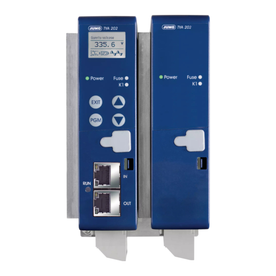
- Page 1 JUMO TYA 202 SCR Power Controller in a three-phase economy circuit 709062/8-01-50 709062/8-01-100 709062/8-01-150 709062/8-01-200 709062/8-01-250 709062/8-01-32 709062/8-01-020 B 709062.0 Operating Manual 2011-07-02/00561073...
- Page 2 All parameter settings are described in detail in the chapter "Configuration". This operating overview shows all possible parameters of the device series. Depending on the order specifications or current configuration, any parameters that are not required are hidden.
-
Page 3: Table Of Contents
Content Introduction..................7 Preface ......................7 Typographical conventions ............... 8 1.2.1 Warning signs ...................... 8 1.2.2 Note signs ......................9 1.2.3 Perform an action ....................9 1.2.4 Representation ....................9 Order specifications ................10 1.3.1 Scope of delivery ....................10 1.3.2 Accessories ...................... - Page 4 Content Cable lugs and plug-in screw terminals ..........30 3.2.1 Type 709062/8-0X-032-XXX-XXX-XX-25X ............30 3.2.2 Type 709062/8-0X-050-XXX-XXX-XX-25X ............31 3.2.3 Type 709062/8-0X-100-XXX-XXX-XX-25X ............32 3.2.4 Type 709062/8-0X-150-XXX-XXX-XX-25X Type 709062/8-0X-200-XXX-XXX-XX-25X ............33 3.2.5 Type 709062/8-0X-250-XXX-XXX-XX-25X ............34 Connection diagram ................35 3.3.1 Three-phase economy circuit, Master/Slave for resistive loads in star, delta circuit or transformer loads (resistive-inductive) ...........
- Page 5 Content Type of soft start......................51 Soft start duration ......................51 Current limiting ........................ 51 current limit ........................51 Resistance limitation......................52 Resistance limit value ...................... 52 Dual energy management....................52 5.1.3 Analog inputs ..................... 53 Current measuring range ....................53 Current measuring range, start..................
- Page 6 Content end value ......................... 61 5.1.9 RS422/485 ......................61 Baud rate ......................... 61 Data format ........................61 Device address ........................ 61 Min. response time ......................61 5.1.10 PROFIBUS-DP ....................62 Device address ........................ 62 Data format ........................62 5.1.11 Changing codes ....................62 Code Manual mode ......................
- Page 7 Content Installation ....................84 Program start ................... 86 Forgotten the code? ................87 Changing the language of the device texts ........... 88 Fault messages and alarms............89 Binary signal for collective fault ............. 93 Replace defective semi-conductor fuse ..........94 8.2.1 Accessories: Semi-conductor fuses ..............
- Page 8 Content 2011-07-01/00561073 [Thyristor Leistungssteller TYA202]...
-
Page 9: Introduction
The power controller may only be operated with original JUMO semi- conductor fuses. Please check that the correct spare part has been used during fuse replacement. -
Page 10: Typographical Conventions
1 Introduction When accessing the inner parts of the device and returning device modules, assemblies or components, please observe the regulations as per EN 61340- 5-1 and EN 61340-5-2 "Protection of electronic devices from electrostatic phenomena". Only use ESD packaging for transport. Please note that we cannot accept any liability for damage caused by ESD (electrostatic discharge). -
Page 11: Note Signs
1 Introduction 1.2.2 Note signs Note This symbol indicates particularly important information. Reference This symbol refers to further information in other manuals, chapters or sections. Footnote Footnotes are remarks referring to specific points in the text. Footnotes consist of two parts: A marker in the text and the footnote text itself. -
Page 12: Order Specifications
1 Introduction 1.3 Order specifications The type plate is affixed to the right-hand side of the case. 1.3.1 Scope of delivery 1 Operating Manual B70.9062.0 1 SCR power controller in the version ordered 1:1 patch cable 2011-07-01/00561073 [SCR Power Controller TYA202]... -
Page 13: Accessories
IN = 250A 70/00083318 1.3.3 General accessories Part Sales No. Setup program 70.9061 TYA 201 70/00544869 (also runs for the TYA 202) USB cable A-plug B-plug 3m 70/00506252 Mounting set for DIN rail installation: Type 70.9062/8-01-20... 70/00555172 Types 70.9062/8-01-32 and 70.9062/8-01-50... -
Page 14: Brief Description
32A have to be fitted to the wall. Operating The TYA 202 operates in burst-firing mode. In burst-firing mode, the first half- modes cycle can be optimally cut back by means of an adjustable phase angle for driving transformer loads. -
Page 15: Standards, Approvals And Conformity
1 Introduction 1.5 Standards, approvals and conformity Test basis for the device characteristics is the Low Voltage Directive DIN EN 50178. Test basis for the EMC Directive is DIN EN 61326-1. Standard Electrical connection DIN VDE 0100 Protection rating IP 20 panel- DIN EN 60529 mounting devices Climatic ambient conditions... - Page 16 1 Introduction 2011-07-01/00561073 [SCR Power Controller TYA202]...
-
Page 17: Installation
A semi-conductor fuse is installed to protect the controller in the event of a ground fault/short circuit. In the event of a fault/defect, it may only be re- placed by an original JUMO semi-conductor fuse. v Chapter 8.2 „Replace defective semi-conductor fuse“... -
Page 18: Ambient Conditions
2 Installation h Load leads and cables for control inputs should be routed separately as far as possible. h Wire up the connections from supply line – SCR power controller – load as per the wiring diagram, and check them. Phase position The voltage supply for the control electronics and the load voltage must have an identical phase position. -
Page 19: Permissible Load Current Depending On The Ambient Temperature
2 Installation filters to deal with any interference problems. Such filters are usually provided as complete modules, ready to be wired into the system. 2.1.3 Permissible load current depending on the ambient temperature Load current/A Reduction at a temperature of 45°C: 2%/Kelvin T/°C Destruction due to overheating:... -
Page 20: Wall Mounting With Screws (Ex Factory)
2 Installation 2.1.4 Wall mounting with screws (ex factory) The power controllers with load current 20...100A are fastened to a fire resis- tant switch cabinet wall with 2 screws. The left-hand hole is better accessible in the top area. The power controllers with load current 150 ... 250A are fastened with 4 screws. - Page 21 2 Installation TYA202 100A TYA202 150/200A 2011-07-02/00561073 [SCR Power Controller TYA202]...
- Page 22 2 Installation TYA202 250A 2011-07-02/00561073 [SCR Power Controller TYA202]...
-
Page 23: Fixing Onto Din Rail (Accessories)
2 Installation surface The power controller heats up during operation depending on the load up to a temperature of 105°C. Ensure that the lamellae of the cooling body are vertically aligned to allow the heat to be dissipated through natural convection. Fire hazard: Do not install any heat sensitive components and devices close to the power controller. -
Page 24: Dimensions
2 Installation 2.2 Dimensions 2.2.1 Type 709062/8-0X-020-XXX-XXX-XX-25X 17.4 2011-07-01/00561073 [SCR Power Controller TYA202]... -
Page 25: Type 709062/8-0X-032-Xxx-Xxx-Xx-25X
2 Installation 2.2.2 Type 709062/8-0X-032-XXX-XXX-XX-25X Subject to technical alterations! 2011-07-01/00561073 [SCR Power Controller TYA202]... -
Page 26: Type 709062/8-0X-050-Xxx-Xxx-Xx-25X
2 Installation 2.2.3 Type 709062/8-0X-050-XXX-XXX-XX-25X Subject to technical alterations! 2011-07-01/00561073 [SCR Power Controller TYA202]... -
Page 27: Type 709062/8-0X-100-Xxx-Xxx-Xx-25X
2 Installation 2.2.4 Type 709062/8-0X-100-XXX-XXX-XX-25X Subject to technical alterations! 2011-07-01/00561073 [SCR Power Controller TYA202]... -
Page 28: Type 709062/8-0X-150-Xxx-Xxx-Xx-25X Type 709062/8-0X-200-Xxx-Xxx-Xx-25X
2 Installation 2.2.5 Type 709062/8-0X-150-XXX-XXX-XX-25X Type 709062/8-0X-200-XXX-XXX-XX-25X Subject to technical alterations! 2011-07-01/00561073 [SCR Power Controller TYA202]... -
Page 29: Type 709062/8-0X-250-Xxx-Xxx-Xx-25X
2 Installation 2.2.6 Type 709062/8-0X-250-XXX-XXX-XX-25X Subject to technical alterations! 2.2.7 Clearances (all types) h Allow a clearance of 10 cm from the floor. h Allow a clearance of 15 cm from the ceiling. h When fitted next to each other, no spacing between the units is required. 2011-07-01/00561073 [SCR Power Controller TYA202]... - Page 30 2 Installation 2011-07-01/00561073 [SCR Power Controller TYA202]...
-
Page 31: Electrical Connection
3 Electrical Connection Dangerous volt- Only allow qualified electricians to carry out the electrical connection! Dangerous voltage will cause electric shock if you come into contact with live components. h Disconnect the system from the electrical supply (all poles). 3.1 Plug-in screw terminals Tools - Slotted screwdrivers, blade width 2, 3 and 5 mm - Ring or open jaw spanner, width across flats 7, 10, 13 mm... -
Page 32: Cable Lugs And Plug-In Screw Terminals
3 Electrical Connection 3.2 Cable lugs and plug-in screw terminals 3.2.1 Type 709062/8-0X-032-XXX-XXX-XX-25X Devices with load current 32...50A are equipped with plug-in screw terminals in the control section and cable lugs in the power section. Terminal Version Conductor cross- Maximum section tightening torque X2_1 and X2_2... -
Page 33: Type 709062/8-0X-050-Xxx-Xxx-Xx-25X
3 Electrical Connection 3.2.2 Type 709062/8-0X-050-XXX-XXX-XX-25X 2011-07-01/00561073 [SCR Power Controller TYA202]... -
Page 34: Type 709062/8-0X-100-Xxx-Xxx-Xx-25X
3 Electrical Connection 3.2.3 Type 709062/8-0X-100-XXX-XXX-XX-25X Devices with load current 75...100A are equipped with plug-in screw terminals in the control section and cable lugs in the power section. Terminal Version Conductor cross- Maximum section tightening torque X2_1 and X2_2 Slotted screws, blade width 2 mm 0.2...1.5mm 0.25 Nm Slotted screws, blade width 3 mm... -
Page 35: Type 709062/8-0X-150-Xxx-Xxx-Xx-25X Type 709062/8-0X-200-Xxx-Xxx-Xx-25X
3 Electrical Connection 3.2.4 Type 709062/8-0X-150-XXX-XXX-XX-25X Type 709062/8-0X-200-XXX-XXX-XX-25X Devices with load current 150A are equipped with plug-in screw terminals in the control section and cable lugs in the power section. Terminal Version Conductor Maximum cross-section tightening torque X2_1 and X2_2 Slotted screws, blade width 2 mm 0.2...1.5mm 0.25 Nm... -
Page 36: Type 709062/8-0X-250-Xxx-Xxx-Xx-25X
3 Electrical Connection 3.2.5 Type 709062/8-0X-250-XXX-XXX-XX-25X Devices with load current 200...250A are equipped with plug-in screw termi- nals in the control section and cable lugs in the power section. Terminal Version Conductor cross- Maximum section tightening torque X2_1 and X2_2 Slotted screws, blade width 2 mm 0.2...1.5mm 0.25 Nm... -
Page 37: Connection Diagram
3 Electrical Connection 3.3 Connection diagram Connection for Screw terminals Connection side Device side Voltage supply for control electronics (corresponds to the max. load voltage of N/L2 ordered device type) Protective earth power section Load connection in the N/L2 Control section Connection for screw terminal X2_1 Connection side... - Page 38 3 Electrical Connection Fault signal output Connection for screw terminal X3 Connection side Device side Relay or optocoupler 13 N/O contact or collector Relay Optocoupler 14 N/C contact 15 pole or emitter Ö Interfaces Connection Modbus RS422 RS485 Connection PROFIBUS-DP Plug-in screw TxD (-) RxD/TxD B(-)
-
Page 39: Three-Phase Economy Circuit, Master/Slave For Resistive Loads In Star, Delta Circuit Or Transformer Loads (Resistive-Inductive)
Master/Slave operation. The two devices are connected by a max. 30 cm patch cable. The figure shows the wiring of a TYA 202 that is available completely installed and configured at the factory but behaves identically to two individual TYA 201 devices in Master/Slave mode. - Page 40 3 Electrical Connection 2011-07-01/00561073 [SCR Power Controller TYA202]...
-
Page 41: Operation
4 Operation Adhere to the The voltage supplies to the control electronics and to the power section must switch-on be switched on simultaneously. sequence Under no circumstances may the voltage supply for the control electronics be switched on before the load voltage! This is especially important for operating transformer loads and resistive loads with a large temperature coefficient (TC >>... -
Page 42: Display Of Measured Values
4 Operation actual value, set point value load resistance, device temperature and power. This information is also shown in the diagnosis window of the setup program. Chapter 7 „Setup program“ 4.1.2 Display of measured values Measured value In this level, the designation of the measured value is shown in the top line and overview the numerical value with the unit in the center. -
Page 43: Display In The Configuration Level
4 Operation 4.1.3 Display in the configuration level Scroll bar The menu point marked with a black background is selected and contains further parameters. If there are more than 3 menu points in a level, a scroll bar appears showing the current position in the menu. -
Page 44: Display Of Error Messages And Particular Statuses
4 Operation 4.1.4 Display of error messages and particular statuses Cyclic The symbols for input, cascade control and operating mode are displayed display alternately in the info line together with error messages or information about particular statuses. Chapter 8 „Fault messages and alarms“ Examples All parameters for the maximum device extension level are listed in the following tables. -
Page 45: Operator Level
4 Operation 4.2 Operator level This contains the parameters that can be changed during operation without a restart (reset). They are factory supplied without a password but can be protected if required with a 4-digit code. Chapter 5.1.11 „Changing codes“ The power controller can be adapted to the system and optimized during operation. -
Page 46: Set Point Value Configuration
4 Operation 10% ... max. load current of the device type +10% Current load current 0...999.99 Current resistance k / Bold = factory setting 4.2.3 Set point value configuration Value range Your setting: 0 ... 180°el Current load voltage and load current 0 ...100...115% - of the maximum load voltage,... -
Page 47: Monitoring
4 Operation 4.2.4 Monitoring The value to be monitored is adjustable. Chapter 5.1.5 „Monitoring“ Load voltage is used in this example. Value range Your setting: 0 ... 9999.9 Current measured value 0 ... 9999.9 Current measured value 0 ...1 ... 9999.9 10...50% Current deviation from teach-in... - Page 48 4 Operation This function is not factory configured. This window only appears after the following setting in the configuration level: h Use the key to change to the configuration level ➔ ➔ h Monitoring Teach-in type load monit. Manual setting h Press the Now the function "Manual teach-in"...
-
Page 49: Configuration
5 Configuration 5.1 Configuration level The configuration level contains the parameters for the configuration of the power controller. If parameters of this level are changed during operation, this causes the power controller to be locked (inhibited). In this state it does not provide any power. When the configuration level is exited, a restart (reset) is performed and the power controller will then provide the required power again. -
Page 50: Device Data
5 Configuration 5.1.1 Device data Basic settings for display and temperature unit Value/settings Description Temperature unit °C Defines the unit for displayed temperatures, such as the device temperature. °F Display contrast 0...50...100 % Light/dark contrast setting Switch off 0000...1440 min The background lighting of the display is switched off after the set number of minutes. -
Page 51: Cascade Control
5 Configuration Value/settings Description Cascade control , U, I , I , P Note: Cascade control only appears when: ➔ SCR control Continuous (controller). Cascade control loops are used to eliminate or compensate for external interference, such as fluctuations in the supply voltage and changes in resistance which would have a nega- tive effect on the control loop. -
Page 52: Cycle Time
5 Configuration Value/settings Description Cycle time Fixed (500ms) This setting is only available in burst-firing mode. (for slow heating ele- For a fixed period of 500ms, for example, at an output level of ments) 20% 5 sine waves are switched on and 20 are switched off. 500ms Fastest possible The cycle time is variable for this setting. -
Page 53: Type Of Soft Start
5 Configuration Value/settings Description The phase angle is steadily reduced starting from 180° until Type of soft start With phase angle control a full wave has passed through. The soft start has been completed and the power controller switches to burst-firing mode. Softstartzeit Note: If the output level drops to 0% for longer than 8 sec- onds, the power controller restarts with a soft start once the... -
Page 54: Resistance Limitation
5 Configuration Value/settings Description Resistance limita- Note: Resistance limitation is only possible for controllers with current and voltage measurement in which the cas- tion order code cade control P (code 001 in the ) is integrated. No resistance limitation The load resistance is monitored to ensure that the set resis- tance limit is not exceeded. -
Page 55: Analog Inputs
5 Configuration 5.1.3 Analog inputs The power controller has a voltage and a current input. These inputs (default set point value) specify the required output at the load output. In most cases this signal is transmitted as a standard signal by an electronic controller or a PLC and is adjusted with these settings. -
Page 56: Set Point Value Configuration
5 Configuration 5.1.4 Set point value configuration Here you can determine the analog input that specifies the set point value, how high the base load should be and which alternative value is to be used in the event of a fault. -
Page 57: Base Load
5 Configuration Base load 0 ...100% Unit depending on the setting for cascade control and device type: - of the maximum - for voltage: 0 ... 115% of the max. load voltage, e.g. 264.5V load voltage, - for current: 0 ...100% of the max. load current, e.g. 20A) - of the max. -
Page 58: Monitoring
5 Configuration 5.1.5 Monitoring An internal measured value can be monitored to ensure the adherence to limit values. Depending on the switching behavior, an overrange or underrange is output at the binary output (option: relay or optocoupler). Value/settings Description Limit value moni- Switched off No monitoring toring... -
Page 59: Load Monitoring
5 Configuration Load monitoring None The load is not monitored. Undercurrent Note: This parameter is only available if the device type is equipped with a cascade control I, I or P, permitting measure- Overcurrent ment of the current. v Chapter 6.1 „Detection of load faults“ Note: This setting is only available if load monitoring for un- dercurrent or overcurrent has been set. -
Page 60: Binary Inputs
5 Configuration 5.1.6 Binary inputs 2 binary inputs are provided, and an additional binary input for firing-pulse in- hibit to which a potential-free contact can be connected. The following functions can be triggered with binary input 1 and 2: ➔ h Use the key to change to the Config level Binary inputs... -
Page 61: Control Direction, Binary Input1
5 Configuration Value/settings Description Control direction, Open, inactive The function for binary input 1 can be triggered when the change-over contact is open or closed. binary input1 Open, active Control direction, Open, inactive The function for binary input 1 can be triggered when the change-over contact is open or closed. -
Page 62: Binary Output
5 Configuration 5.1.7 Binary output This parameter is used to specify the control direction of the binary output. It is con- trolled by the multi-input interference signal. v Chapter 8.1 „Binary signal for collective fault“ ➔ h Use the key to change to the Config level Binary output Value/settings Description... -
Page 63: Actual Value Output
5 Configuration 5.1.8 Actual value output The actual value output is an analog output at which different internal values can be output as a standard signal. Value/settings Description Signal type of The standard signal to be output at the actual value output is actual value output set here. -
Page 64: Profibus-Dp
5 Configuration 5.1.10 PROFIBUS-DP Interface parameter for PROFIBUS-DB (see separate manual) Value/settings Description Device address 1 ...125 If a "0" is set for the device address, the bus fault error message is not displayed. Data format Motorola, Intel k / Bold = factory setting 5.1.11 Changing codes It is possible to enter passwords (4-digit numeric codes) for manual mode, operator level and configuration level to protect them from unauthorized... -
Page 65: Configuration Example
Base load: 0%; maximum output level 100% Default set point value via input signal of 0 ... 20mA. These requirements are sufficient for the following power controllers: Device type 70.9062/8-01-020-100-400-252 L2 L3 TYA 202 Setpoint lnput: 0(4)...20mA Attention: - make sure that the rotating Patchcable... - Page 66 5 Configuration 2011-07-01/00561073 [SCR Power Controller TYA202]...
-
Page 67: Special Device Functions
6 Special device functions 6.1 Detection of load faults The load monitoring function can detect and signal a load failure, a partial load failure or a partial load short circuit. Undercurrent This function is used for one or more heating elements connected in parallel that are to be monitored for breakage. - Page 68 6 Special device functions Overcurrent Number of Star connec- Delta connection heating ele- tion without ments neutral conduc- Example for 2 heating ele- ments The specifications in % refer to load current changes Temperature For heating elements with large positive or negative temperature coefficients it coefficient (TC) is necessary to determine a suitable limit value yourself.
-
Page 69: Teach-In
6 Special device functions 6.1.1 Teach-In Depending on the configuration of the parameter "Load monit. teach-in", teach-in, i.e. determination of the last measured values in the OK status, is ei- ther executed automatically once after mains ON or repeatedly automatically (cyclically) after 1 minute has elapsed or manually. -
Page 70: Manual Mode
6 Special device functions 6.2 Manual mode In this case, the set point value can be manually preset in % without the need for external wiring via the analog input. 6.2.1 Default set point value in manual mode Start Manual mode, as set in the factory, can be accessed without entering a code. h Press the key 1 x (manual mode) h Press the... -
Page 71: Performing Teach-In In Manual Mode
6 Special device functions 6.2.3 Performing teach-in in manual mode The power controller is in the level "Measured value overview". h Press the key 2 x to return to manual mode. If the teach-in is being performed for the first time, the message "Teach-in load monitoring"... -
Page 72: Default Set Point Value Via Potentiometer
6 Special device functions 6.3 Default set point value via potentiometer For this connect a potentiometer to the voltage input. It is supplied with DC 10V at terminal 5 of the power controller. ➔ ➔ h Set Configuration level Analog inputs Voltage measuring range to 0...10V ➔... - Page 73 6 Special device functions Attention: L2 L3 TYA 202 - make sure that the rotating electric field is right handed! - only possible in burst firing mode - SCR load voltage =U Setpoint lnput: 0(4)...20mA Device 1 Patchcable Relay Optocoupler Ö...
- Page 74 6 Special device functions The two controllers switch on at an offset time. The energy output is symmetri- cal on each side of the broken line (see arrows). Overlapping of the two device currents in one phase is avoided as long as the sum of the output level of the two devices is lower than 100%.
-
Page 75: Cascade Control
6 Special device functions 6.5 Cascade control Cascade control loops are used to eliminate or compensate for external interference, such as fluctuations in the supply voltage and changes in resistance which would have a negative effect on the control loop. 6.5.1 Closed control loop without cascade control Supply voltage... -
Page 76: Closed Control Loop With A Subordinate Control
6 Special device functions The controller recognizes the deviation through the relatively slow response of the temperature control loop and increases its output level (yR) until the furnace reaches the original temperature (250°C) again. 6.5.2 Closed control loop with a subordinate control To avoid power variations caused by supply voltage fluctuations, a subordinate control loop is built into the controller system. - Page 77 6 Special device functions input signal of power controller (0 ... 20 mA) Load Heating elements that have a positive temperature coefficient (TC), i.e. where the electrical resistance increases with increasing temperature, are usually driven from a power controller that incorporates a subordinate U control () (Figure 1).
- Page 78 6 Special device functions value. This damps out any tendency to overshoot the final temperature. Other applications for U control are: - In lighting systems: In this case, the intensity of the illumination is proportional to U - Some resistance materials have a TC that is close to 1. These include heating elements made from nickel /chrome, constantan etc.
- Page 79 6 Special device functions Looking at the power equation P = I · R, we can see that an I control has the same regulatory effect on the power as already described for the U control. In other words, by regulating a constant current while the temperature rises, the power in the process is automatically reduced as the resistance falls.
- Page 80 6 Special device functions Which operating mode Operating mode resistive load Inductive load is suitable for which load? TC constant TC positive TC nega- Long- tive term ag- burst-firing mode Burst-firing mode with a start Burst-firing mode with current limiting Cascade control 2011-07-01/00561073 [SCR Power Controller TYA202]...
-
Page 81: Resistance Limitation (R Control)
6 Special device functions 6.6 Resistance limitation (R control) This is only possible in power controllers with current and voltage measurement that are fitted with cascade control P (Code 001 in the order code) and only functions for load resistors with positive temperature coefficient. -
Page 82: Current Limiting
6 Special device functions 6.7 Current limiting Factory setting No current limiting is activated. Chapter 5.1.2 „Power controller“ 6.8 a start Factory setting The phase angle of the first half-wave (a start) is not activated. For transformer loads, the SCR power controllers are operated in burst-firing mode with phase angle cut-back for the first half-wave. -
Page 83: Firing-Pulse Inhibit
6 Special device functions 6.10 Firing-pulse inhibit The inhibit function serves for protecting the SCR power controller and the connected devices. Internal The SCR output is inhibited for the following: - Device switch-on (during the starting process) - Reset or restart due to changes in the configuration level - Insufficient or excessive supply voltage - Master/slave data line interrupted - Master/slave synchronization failed... - Page 84 6 Special device functions 2011-07-01/00561073 [SCR Power Controller TYA202]...
-
Page 85: Setup Program
7 Setup program The setup program allows all data for the device to be conveniently set using the PC and transmitted to the device. To configure the power controller, simply connect the power controller to the PC with the USB cable. As soon as the device is switched on, this configuration data is automatically applied. -
Page 86: Installation
7 Setup program 7.2 Installation h Install the setup program. h Start the setup program. h Use the supplied USB cable to connect the socket of the power controller to a USB socket of the PC. The connected hardware will be detected. Installation steps 2011-07-01/00561073 [SCR Power Controller TYA202]... - Page 87 7 Setup program Installation steps Automatic detection Complete language setting 2011-07-01/00561073 [SCR Power Controller TYA202]...
-
Page 88: Program Start
7 Setup program 7.3 Program start h Start the setup program via the windows start menu h Click Connect in the menu bar Diagnosis The diagnosis window appears at the bottom of the screen with the current measured data. The connection has thus been established. There is no power from the power controller during the transmission of setup data "to the device". -
Page 89: Forgotten The Code
7 Setup program 7.4 Forgotten the code? If you have forgotten your password, you can read out the device data via the setup program or enter a new code. ➔ h Perform a Data transfer Reading out From the device setup data The read out codes are visible in the device data menu. -
Page 90: Changing The Language Of The Device Texts
7 Setup program 7.5 Changing the language of the device texts The factory set language is specified in the order details. Only one language can be transmitted to the device with the setup program. h Connect the device to the PC using the USB cable h Start the setup program ➔... -
Page 91: Fault Messages And Alarms
- Check the line fuse for the load circuit Malfunction SCR defective The device must be returned to SCR breakage JUMO for repair. h Return the device SCR defective The device must be returned to short-circuit JUMO for repair. Return the device Attention! Device temperature is higher than 100°C... - Page 92 8 Fault messages and alarms Error message Cause Remedy Supply voltage is Supply voltage is not within specified tol- Check nominal voltage of the too low erance range device type v Chapter 10.1 „Voltage supply, load v Chapter 1.3 „Order specifi- current“...
- Page 93 - Check the line fuse for the load circuit Slave: SCR defective The device must be returned to SCR breakage JUMO for repair. h Return the device Slave: SCR SCR defective The device must be returned to short-circuit JUMO for repair.
- Page 94 8 Fault messages and alarms Error message Cause Remedy Slave: Attention! Device temperature is higher than 100°C - Ensure adequate ventilation high temp. - Reduce load current - Use SCR power controller with higher maximum load current Slave: Limit. Device temperature is higher than 105°C - Ensure adequate ventilation active, high temp.
-
Page 95: Binary Signal For Collective Fault
8 Fault messages and alarms 8.1 Binary signal for collective fault This signal is used for controlling the binary output and LED K1, and can also be read out from the power controller via the interfaces. Using the setup program it is possible to configure which events (alarm and er- ror messages) are to be grouped together as a binary signal for a collective fault. -
Page 96: Replace Defective Semi-Conductor Fuse
8 Fault messages and alarms 8.2 Replace defective semi-conductor fuse Opening the case Caution! Risk of burns! The device can heat up during operation at the cooling body. The current device temperature is shown on the display. v Operating overview (on the first cover page) h Disconnect the built-in device from the voltage supply (all poles) v Chapter 3.3 „Connection diagram“... -
Page 97: Accessories: Semi-Conductor Fuses
8 Fault messages and alarms 8.2.1 Accessories: Semi-conductor fuses The design of the semi-conductor fuse differs according to the device type. Power Tripping current Screws Tighten- Sales controller number type torque Tripping current: 50A Recessed head 70/00513108 32 A Tripping current: 80A Recessed head 70/00068011 Tripping current: 80A Recessed head 70/00068011... -
Page 98: Semi-Conductor Fuses Type 709062/8-0X-32
8 Fault messages and alarms h Undo 2 recessed head screws. h Replace the defective semi-conductor fuse with a new one. h Tighten the screws with the specified tightening torque. 8.2.3 Semi-conductor fuses type 709062/8-0X-32... 2011-07-01/00561073 [SCR Power Controller TYA202]... - Page 99 8 Fault messages and alarms h Undo 2 hexagon head screws. h Replace the defective semi-conductor fuse with a new one. h Tighten the screws with the specified tightening torque. h Push the plastic case back into the guide rails until the spring clip engages. Re-assemble the case 2011-07-01/00561073 [SCR Power Controller TYA202]...
- Page 100 8 Fault messages and alarms 2011-07-01/00561073 [SCR Power Controller TYA202]...
-
Page 101: What To Do If
9 What to do if ... What is happening ? Cause / Remedy Information v Chapter 5.1.1 „De- Green LED Power is - Display switch-off active flashing vice data“ h Press any key Power controller is not - Parameters have been changed in the producing any output configuration level but not completed. - Page 102 9 What to do if ... What is happening ? Cause / Remedy Information v See “Current limit- Power controller does - Current limiting active not produce full power ing” on page 51. h Check settings although set point value - Half-wave control set is set to 100% (50% capacity)
-
Page 103: Technical Data
10 Technical data 10.1 Voltage supply, load current Voltage supply Corresponds to the load voltage selected for the device type Control section power consumption max.20 VA Load voltage U AC 24V -20%...+15%, 45 ...63 Hz L eff AC 42V -20%...+15%, 45 ...63 Hz AC 115V -20%...+15%, 45 ...63 Hz AC 230V -20%...+15%, 45 ...63 Hz AC 265V -20%...+15%, 45 ...63 Hz... -
Page 104: Analog Inputs (Only Master)
10 Technical data 10.3 Analog inputs (only master) Current 0 (4) … 20mA Ri = 50 W Voltage 0 (2) … 10V Ri = 25 kW 0 (1) … 5V Ri = 25 kW 10.4 Analog output (actual value output, only master) Analog output Switched off as standard. -
Page 105: General Characteristic Data
10 Technical data 10.7 General characteristic data Circuit options - Three-phase economy circuit in master slave operation Operating mode: - Burst-firing operation for resistive or transformer load Special features - Dual energy management - Soft start with pulse groups Cascade control U²... - Page 106 10 Technical data Weight Load current 20A approx. 2200g kg Load current 32 approx. -- kg Load current 50A approx. -- kg Load current 100A approx. -- kg Load current up to 150A approx. -- kg Load current 200 to 250A approx. -- kg Standard accessories 1 operating manual B 70.9062.0 2011-07-01/00561073 [SCR Power Controller TYA202]...
- Page 108 JUMO GmbH & Co. KG JUMO Instrument Co. Ltd. JUMO Process Control, Inc. Street address: JUMO House 8 Technology Boulevard Moritz-Juchheim-Straße 1 Temple Bank, Riverway Canastota, NY 13032, USA 36039 Fulda, Germany Harlow - Essex CM20 2DY, UK Phone: 315-697-JUMO...
Need help?
Do you have a question about the TYA 202 and is the answer not in the manual?
Questions and answers