Sign In
Upload
Manuals
Brands
JUMO Manuals
Controller
B 703571.0
User Manuals: JUMO B 703571.0 process controller
Manuals and User Guides for JUMO B 703571.0 process controller. We have
1
JUMO B 703571.0 process controller manual available for free PDF download: Operating Manual
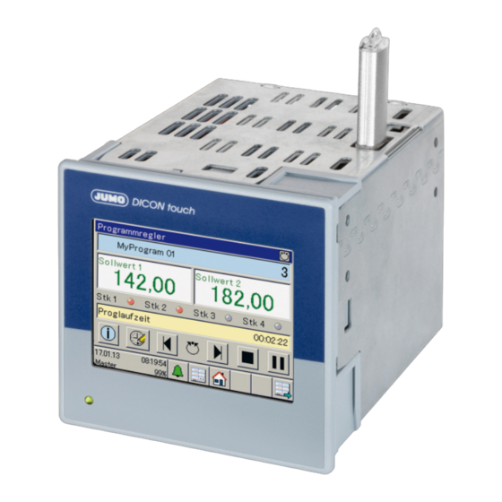
JUMO B 703571.0 Operating Manual (174 pages)
Two-channel process and program controller with touchscreen 8.9 cm
Brand:
JUMO
| Category:
Controller
| Size: 7 MB
Table of Contents
Table of Contents
3
Introduction
9
Safety Information
9
Warning Symbols
9
Note Signs
9
Representation
10
Description
11
Block Diagram
12
Identifying the Device Version
13
Order Details
14
Scope of Delivery
16
General Accessories
16
Accessories
17
Nameplate
18
Mounting
19
Mounting Site and Climatic Conditions
19
Environmental Influences
19
Case
19
Electrical Data
20
Dimensions
21
Close Mounting
21
Insertion in Panel Cut-Out
22
Care and Treatment of the
22
Electrical Connection
25
Installation Notes
25
Cables, Shielding, and Grounding
25
Electrical Safety
25
Intended Use, Misuse
25
Galvanic Isolation
26
Connection Diagram
27
Connection Elements
27
Analog Inputs
28
Analog Outputs
29
Digital Inputs
29
Digital Outputs
29
Voltage Supply (According to Nameplate)
32
Interfaces
32
Operation
35
Display and Operating Concept
35
Alarm and Event List
36
Function Buttons, History and Channel Changeover
36
Images in the Operating Loop
37
Controller Screen 1, Controller Screen 2 and Controller Overview
37
Program Controller
39
General Screen 1.2
40
Recording Image
40
Process Screen
41
Login
43
Logging on
44
Logging out
44
Changing the Password
44
User Level (Log-In)
45
Example 4 Transferring Controller Setpoint Values to the User Level
45
Program Administration
47
Enter Program Curves
47
On the Device
47
About the Setup Program
48
Section Run Time
49
Control Contacts
49
Tolerance Band
50
Number of Repetitions
50
Start Section
50
Parameter Block
50
Device Information
51
General Information
51
Version, Motherboard, Ethernet Information
51
Slots
51
Inputs/Outputs
51
Digital and Analog Inputs, Digital and Analog Outputs, External Digital, and External Analog Inputs
52
Functions
52
Mathematics, Logic Signal, Limit Value Outputs
52
Timer Signal, Digital Controller Signals, Control Contacts, Controller, Analog Flag, Digital Flag
53
Status
53
Ethernet Status 1 to 9
53
Functional Level
55
General Information
55
Activate Functional Level
55
Parameterization
57
Date and Time
57
Daylight Saving Time
57
Controller/Parameter Blocks
58
Setpoint Values
62
Entered on the Device
63
Entered Using the Setup Program
63
Configuration
65
Analog Selector
65
Basic Settings
70
Digital Inputs IN1 to 7
72
Analog Inputs IN8, IN9, IN10, IN11
73
Alarms
76
Controller Configuration
77
Controller Inputs
80
Self-Optimization Controller
82
Control Loop Monitoring
87
Output Level Monitoring
90
Controller Setpoint Values
93
Ramp Function
95
Digital Outputs
97
Analog Outputs
98
Limit Value Monitoring
100
Function and Hysteresis
103
Hysteresis
103
Start-Up Alarm Suppression
104
Acknowledging Self-Locking
104
Alarm
105
Screen
106
2Configurating the Screen
107
3Start Screen and Watermark
107
4Operating Loop
108
6Color for Controller Screens 1, 2
110
Recording
113
1Parameter
113
2Analog Channels
115
3Digital Channels
115
Program Controller
116
1Controller Signals
118
2Extended Functions
119
Timer or Time Switch
124
Digital Controller Signals
126
1Alarms
128
Mathematics/Logic
130
Flags/Service
132
1Flags
132
2Service
133
External Digital Inputs
134
External Analog Inputs
135
1Alarms
136
Serial Interfaces
137
Modbus TCP
138
Relay Module (Accessories)
139
PROFIBUS DP (Option)
140
Configuration - in Setup Program Only
141
Installing the Setup Program
141
Hardware
141
Software Requirements
141
Starting the Setup Program
141
Establish the Connection to the Device
142
Setup Data Transfer on or from the External Mass Storage Device
143
Country Settings
144
User List
144
User Level
145
E-Mail
145
Web Server
145
Modbus Frames for Reading
146
Modbus Frames for Writing
147
Customer-Specific Linearization
148
1Grid Points
148
2Formula
149
Process Screen
151
2Background
153
5Preview Screen
157
Special Functions
159
Calibrating the Touchscreen
159
Online Parameter
161
Fine Adjustment
161
Ethernet (Option)
163
Date and Time
164
Screenshot
164
Deleting Measurement Data Memory
164
Enabling of Extra Codes
165
Testing Calibration
166
Various Process Values
166
Error and Alarm Messages
167
Error Messages in Float Values and on the Display
167
Display of Error Messages for Binary Values
167
Retrofitting Optional Boards
169
Safety Information
169
Identifying the Modules
169
Installing Modules
170
Accessories
172
Advertisement
Advertisement
Related Products
JUMO dTRON 16.1 B 70.3011
JUMO B 70.1050.0
JUMO B 70.7011.0
JUMO mTRON B 70.4010.4
JUMO mTRON B 70.4015.4
JUMO iTRON B 70.2040
JUMO B 709720.5
JUMO B 70.9040
JUMO B70.1170.0
JUMO B 707025.0
JUMO Categories
Transmitter
Measuring Instruments
Controller
Thermostat
Voice Recorder
More JUMO Manuals
Login
Sign In
OR
Sign in with Facebook
Sign in with Google
Upload manual
Upload from disk
Upload from URL