Table of Contents
Advertisement
Quick Links
Advertisement
Table of Contents

Related Manuals for AXIOMTEK GOT-3571T


Summary of Contents for AXIOMTEK GOT-3571T
- Page 1 GOT-3571T 5.7” VGA TFT Fanless Touch Panel computer User’s Manual...
-
Page 2: Disclaimers
AXIOMTEK assumes no responsibility for any inaccuracies that may be contained in this document. AXIOMTEK makes no commitment to update or to keep current the information contained in this manual. AXIOMTEK reserves the right to make improvements to this document and/or product at any time and without notice. - Page 3 Safety Approvals CE Marking FCC Class A FCC Compliance This equipment has been tested and complies with the limits for a Class A digital device, pursuant to Part 15 of the FCC Rules. These limits are designed to provide reasonable protection against harmful interference in a residential installation.
- Page 4 Turn OFF the system power before cleaning. Clean the system using a cloth only. Do not spray any liquid cleaner directly onto the screen. The GOT-3571T comes with a touch screen. Although the touch screen is chemical resistant, it is recommended that you spray the liquid cleaner on a cloth first before wiping the screen.
- Page 5 Trademarks Acknowledgments AXIOMTEK is a trademark of AXIOMTEK Co., Ltd. IBM, PC/AT, PS/2, VGA are trademarks of International Business Machines Corporation. Intel and Pentium are trademarks of Intel Corporation. MS-DOS, Microsoft C and Quick BASIC are trademarks of Microsoft Corporation.
- Page 6 This page does not contain any information.
-
Page 7: Table Of Contents
Table of Contents Disclaimers ......................ii Chapter 1 Introduction ..............1 General Description ................. 1 Specifications................... 2 1.2.1 Main CPU board................2 1.2.2 I/O System ..................2 1.2.3 System Specification ................ 3 Dimensions ..................3 I/O Outlets..................5 Package list ..................6 Chapter 2 Hardware Installation.......... - Page 8 MEMO Table of Contents...
-
Page 9: Chapter 1 Introduction
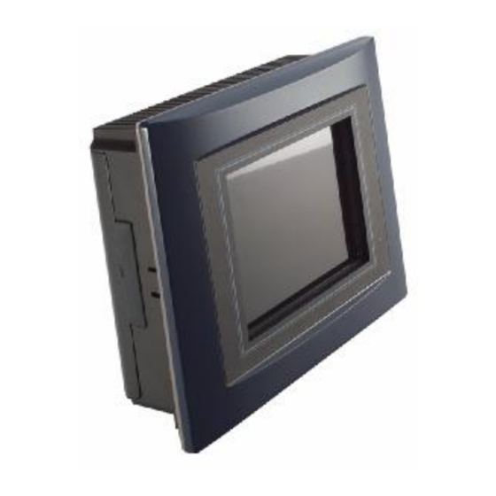
Dimensions I/O Outlets Package List General Description The GOT-3571T is a 5.7” fanless TFT VGA touch panel computer. It is equipped with CISI-based low power consumption processor, AMD LX800. By supporting the option of external battery set, the GOT-3571T can continue system operation if a main power shortage ever happens. -
Page 10: Specifications
GOT-3571T User’s Manual Specifications 1.2.1 Main CPU board n CPU: AMD LX800 500MHz n System Chipset: AMD LX + CS5536AD n BIOS: Phoenix-Award 4Mbit with RPL/PXE Ethernet Boot ROM, Smartview and customer CMOS backup. n System Memory: One 200-pin DDR SODIMM Maximum up to 1GB 1.2.2... -
Page 11: System Specification
GOT-3571T User’s Manual 1.2.3 System Specification 5.7” VGA TFT LCD Disk drive housing: − Compact Flash Type II Socket DC 24V power input Heat dispensing design Net weight: − 2.0 Kgs Dimension (main body size): − 208.5 x 167.3 x 66.5 mm Operating temperature: −... - Page 12 GOT-3571T User’s Manual Note: The unit of length is millimeter. Introduction...
-
Page 13: I/O Outlets
GOT-3571T User’s Manual I/O Outlets The following figure shows the I/O locations of the GOT-3571T. Power Switch DC power connector USB 2.0 x 2 COM 2 (RS-232) Line-out COM 1 (RS-232/422/485) CompactFlash card PC/104 slot Introduction... -
Page 14: Package List
GOT-3571T User’s Manual Package list When you receive the GOT-3571T, there are following items in the package. If you can not find it, please contact AXIOMTEK distributors. 1. GOT-3571T x 1 2. Panel mount kit x 6 3. Driver CD x1... -
Page 15: Chapter 2 Hardware Installation
C h a p t e r Hardware Installation The GOT-3571T provides rich I/O ports and flexible expansions for you to meet different demand such as PCMCIA, WLAN module and so on. The chapter will show you how to install the hardware. It includes :... -
Page 16: Compactflash Card Installation
GOT-3571T User’s Manual CompactFlash Card Installation GOT-3571T offers one CF slot for users to install CompactFlash card. Please refer to the following instructions and illustration: Remove the rubber cover at left-side. Install CompactFlash card in the GOT-3571T. Hardware Installation... -
Page 17: Pc/104 Installation
GOT-3571T User’s Manual PC/104 Installation The GOT-3571T offers a convenient expansion for users to install PC/104 module such as PCMCIA, WLAN, COM port card and so on. Please follow the steps: 1. Unscrew screws to remove the bracket. 2. Install PC/104 module. -
Page 18: Serial Port Interface
GOT-3571T User’s Manual PC/104 Bus Pin Assignment Pin Pin Name Pin Pin Name Pin Pin Name Pin Pin Name IOCHCHK RESETDRV IRQ9 10 -5V 11 SD3 12 DRQ2 13 SD2 14 -12V 15 SD1 16 ENDXFR 17 SD0 18 +12V... - Page 19 GOT-3571T User’s Manual In addition, COM1 can be set for RS-232/422/485 by jumper. The jump setting is listed as below: COM1 JP12 JP10 JP11 RS-232 (default) 3-5, 4-6 3-5, 4-6 RS-422 3-4, 7-8 1-3, 2-4 1-3, 2-4 RS-485 5-6, 7-8...
-
Page 20: Ethernet
Rx- (Data reception negative) RJ-45 RJ45 termination RJ45 termination 2.5 Mounting Way : Panel mount The GOT-3571T is designed for panel mount application. To mount the GOT-3571T, the standard set of mounting kit (included in the system packaging) is needed. Hardware Installation... -
Page 21: Chapter 3 Phoenix-Award Bios Utility
GOT-3571T User’s Manual C h a p t e r 3 Phoenix-Award BIOS Utility The Phoenix-Award BIOS provides users with a built-in Setup program to modify basic system configuration. All configured parameters are stored in a battery-backed-up RAM (CMOS RAM) to save the Setup information whenever the power is turned off. -
Page 22: Control Keys
GOT-3571T User’s Manual Control Keys Move cursor to the previous item Up arrow Move cursor to the next item Down arrow Move cursor to the item on the left hand Left arrow Move to the item in the right hand... -
Page 23: The Main Menu
GOT-3571T User’s Manual The Main Menu Once you enter the Award BIOS CMOS Setup Utility, the Main Menu appears on the screen. In the Main Menu, there are several Setup functions and a couple of Exit options for your selection. Use arrow keys to select the Setup Page you intend to configure then press <Enter>... -
Page 24: Standard Cmos Setup Menu
GOT-3571T User’s Manual 3.5 Standard CMOS Setup Menu The Standard CMOS Setup Menu displays basic information about your system. Use arrow keys to highlight each item, and use <PgUp> or <PgDn> key to select the value you want in each item. - Page 25 GOT-3571T User’s Manual IDE Primary Master/Primary Slave These items identify the types of each IDE channel installed in the computer. There are 45 predefined types (Type 1 to Type 45) and 2 user’s definable types (Type User) for Enhanced IDE BIOS.
- Page 26 GOT-3571T User’s Manual Halt On This item determines whether the system will halt or not, if an error is detected while powering up. The system booting will halt on any errors detected. No errors (default) Whenever BIOS detects a non-fatal error, the All errors system will stop and you will be prompted.
-
Page 27: Advanced Bios Features
GOT-3571T User’s Manual Advanced BIOS Features This section allows you to configure and improve your system, to set up some system features according to your preference. First/Second/Third Boot Device These items let you select the 1 , and 3 devices that the system will search for during its boot-up sequence. - Page 28 GOT-3571T User’s Manual l Gate A20 Option The default value is “Fast”. Normal The A20 signal is controlled by keyboard controller or chipset hardware. Fast Default: Fast. The A20 signal is controlled by Port 92 or chipset specific method. Typematic Rate Setting This item determines the typematic rate of the keyboard.
- Page 29 GOT-3571T User’s Manual l Security Option This item allows you to limit access to the system and Setup, or just to Setup. The default value is “Setup”. If a wrong password is entered at the prompt, the system System will not boot, the access to Setup will be denied, either.
-
Page 30: Advanced Chipset Features
GOT-3571T User’s Manual 3.7 Advanced Chipset Features This section contains completely optimized chipset’s features on the board that you are strongly recommended to leave all items on this page at their default values unless you are very familiar with the technical specifications of your system hardware. - Page 31 GOT-3571T User’s Manual “254M”. l Output Display This item allows you to choose the output for your system display. Configuration options are “CRT”, “Flat Panel” and “Panel & CRT”. The default value is “Panel & CRT”. Flat Panel Configuration Scroll to this item and press <Enter> to view the Flat Panel Configuration sub menu.
-
Page 32: Integrated Peripherals
GOT-3571T User’s Manual Select the shift clock (SHFCLK) to be either free running, or active only during the display period. Some TFT panels recommend keeping the shift clock running during the retrace time. Ø LP Active Period Select the polarity of the LDE/MOD pin. This can be used for panels that require an active low timing LDE interface signal. - Page 33 GOT-3571T User’s Manual l Super IO Device Scroll to this item and press <Enter> to view the sub menu Super IO Device. Ø Onboard Serial Port 1/2/3 Select an address and corresponding interrupt for the serial port. Options: 3F8/IRQ4, 2F8/IRQ3, 3E8/IRQ10, 2E8/IRQ11, 338/IRQ5, 238/IRQ7, Auto and Disabled.
- Page 34 GOT-3571T User’s Manual l IDE Function Setup Scroll to this item and press <Enter> to view the sub menu IDE Function Setup. Ø Master/Slave Drive PIO Mode The four IDE PIO (Programmed Input/Output) fields let you set a PIO mode (0-4) for each of the four IDE devices that the onboard IDE interface supports.
- Page 35 GOT-3571T User’s Manual read/writes per sector the drive can support. Press <Esc> to return to the Integrated Peripherals page. l Onboard Device Scroll to this item and press <Enter> to view the sub menu Onboard Device. Ø Onboard Audio Use this item to enable or disable the onboard Audio function.
- Page 36 GOT-3571T User’s Manual l ITE8888 Configure Scroll to this item and press <Enter> to view the sub menu ITE8888 Configure. Press <Esc> twice to return to the Main Menu page. Phoenix-Award BIOS Utility...
-
Page 37: Power Management Setup
GOT-3571T User’s Manual 3.9 Power Management Setup The Power Management Setup allows you to save energy of your system effectively. It will shut down the hard disk and turn OFF video display after a period of inactivity. l ACPI Function This item allows you to enable/disable the Advanced Configuration and Power Management (ACPI). - Page 38 GOT-3571T User’s Manual l Suspend Mode After a selected period of system inactivity (1 minute to 1 hour), all devices except the CPU shut off. The default value is “Disabled”. Disabled The System will never enter the SUSPEND mode. 1/2/4/6/8/10/2...
-
Page 39: Pnp/Pci Configuration Setup
GOT-3571T User’s Manual 3.10 PnP/PCI Configuration Setup This section describes the configuration of PCI (Personal Computer Interconnect) bus system, which allows I/O devices to operate at speeds close to the CPU speed while communicating with other important components. This section covers very technical items that only experienced users could change default settings. - Page 40 GOT-3571T User’s Manual Resources Controlled By The Phoenix-Award Plug and Play BIOS can automatically configure all boot and Plug and Play-compatible devices. If you select Auto, all interrupt request (IRQ), DMA assignment, and Used DMA fields disappear, as the BIOS automatically assigns them.
-
Page 41: Pc Health Status
GOT-3571T User’s Manual 3.11 PC Health Status This section supports hardware monitoring that lets you monitor those parameters for critical voltages, temperatures and fan speed of the board. Current SYSTEM Temp Show you the current system temperature. Current CPU Temp The current system CPU temperature will be automatically detected by the system. -
Page 42: Load Optimized Defaults
GOT-3571T User’s Manual 3.12 Load Optimized Defaults This option allows you to load your system configuration with default values. These default settings are optimized to enable high performance features. To load CMOS SRAM with SETUP default values, please enter “Y”. If not, please enter “N”. -
Page 43: Set Supervisor/User Password
GOT-3571T User’s Manual 3.13 Set Supervisor/User Password You can set a supervisor or user password, or both of them. The differences between them are: Supervisor password: You can enter and change the options on the setup menu. User password: You can just enter, but have no right to change the options on the setup menu. -
Page 44: Save & Exit Setup
GOT-3571T User’s Manual 3.14 Save & Exit Setup This section allows you to determine whether or not to accept your modifications. Type “Y” to quit the setup utility and save all changes into the CMOS memory. Type “N” to bring you back to the Setup utility. -
Page 45: Exit Without Saving
GOT-3571T User’s Manual 3.15 Exit Without Saving Select this option to exit the Setup utility without saving changes you have made in this session. Type “Y”, and it will quit the Setup utility without saving your modifications. Type “N” to return to the Setup utility. - Page 46 GOT-3571T User’s Manual MEMO Phoenix-Award BIOS Utility...
-
Page 48: Chapter 4 Driver Installation
C h a p t e r 4 Driver Installation System GOT-3571T supports Windows Vista/XP. To facilitate the installation of the system driver, please carefully read the instructions in this chapter before start installing. 1. Here is the path for the system driver: \Driver\XP\ 2. -
Page 49: Touch Screen
GOT-3571T User’s Manual Touch Screen 4.2.1 Specification 5-wire Analog Resistive type Touch Screen PenMount DMC9000 Touch Screen Controller IC Touch Screen Controller RS-232 Communications 19200 baud rate fixed Baud Rate 1024 x 1024 (10 bit A/D converter inside) Resolution 2.7V ~ 5.5V Power Input Active: 3.6mA / Idle Mode: 1.0mA... -
Page 50: Driver Installation - Windows Vista/Xp
GOT-3571T User’s Manual 4.2.2 Driver Installation - Windows Vista/XP The GOT-3571T provides a driver of the touch screen that users can install it under operating system Windows Vista/XP. To facilitate this touch screen driver installation, users should read the instructions in this chapter carefully before start the installation. - Page 51 GOT-3571T User’s Manual Select the “Standard Calibrate” tab. Phoenix-Award BIOS Utility...
- Page 52 GOT-3571T User’s Manual Calibration: To adjust the display with touch panel, click “Calibration” and follow the calibrate point to do calibration; there are five points on screen for calibration. Press OK. Phoenix-Award BIOS Utility...
Need help?
Do you have a question about the GOT-3571T and is the answer not in the manual?
Questions and answers