Table of Contents
Advertisement
Quick Links
Advertisement
Table of Contents

Related Manuals for Rohde & Schwarz R&S RT-ZD40


Summary of Contents for Rohde & Schwarz R&S RT-ZD40
- Page 1 ® R&S RT-ZD40 Active Differential Probe User Manual (>:ÃÍ2) 1410536302 Version 06...
- Page 2 ® This user manual describes the following R&S RT-ZD models and options: ● R&S ® RT-ZD40 (1410.5205.02) © 2023 Rohde & Schwarz GmbH & Co. KG Muehldorfstr. 15, 81671 Muenchen, Germany Phone: +49 89 41 29 - 0 Email: info@rohde-schwarz.com Internet: www.rohde-schwarz.com Subject to change –...
-
Page 3: Table Of Contents
® Contents R&S RT-ZD40 Contents 1 Safety and regulatory information........5 1.1 Safety instructions................5 1.2 Labels on the product................7 1.3 Warning messages in the documentation.......... 8 2 Product description...............9 2.1 Key features and key characteristics..........9 2.1.1 Key characteristics..................9 2.1.2 Key features..................10 2.2 Unpacking and checking..............11 2.3 Description of the probe..............11 2.3.1 Probe head................... - Page 4 ® Contents R&S RT-ZD40 4.3 R&S ProbeMeter..................27 4.4 Offset compensation................28 4.4.1 Differential offset................... 28 4.4.2 Common mode offset................29 4.5 Characteristics of differential probes..........31 4.5.1 Common mode rejection ratio (CMRR)..........32 4.5.2 Dynamic range and operating voltage window........33 4.5.3 Ground connection................34 4.6 Measurement principles..............34 4.6.1 Signal integrity of the transferred signal..........36 4.6.2 Signal loading of the input signal............
-
Page 5: Safety And Regulatory Information
® Safety and regulatory information R&S RT-ZD40 Safety instructions Safety and regulatory information The product documentation helps you to use the product safely and efficiently. Follow the instructions provided here and throughout the manual. Intended use The product is intended for the development, production and verification of elec- tronic components and devices in industrial, administrative, and laboratory envi- ronments. - Page 6 ® Safety and regulatory information R&S RT-ZD40 Safety instructions sheet, manuals and the printed "Safety Instructions for Oscilloscopes and Acces- sories" document. If you are unsure about the appropriate use, contact Rohde & Schwarz customer service. Using the product requires specialists or specially trained personnel. These users also need sound knowledge of at least one of the languages in which the user interfaces and the product documentation are available.
-
Page 7: Labels On The Product
® Safety and regulatory information R&S RT-ZD40 Labels on the product Consider that the rated voltage depends on the frequency. The voltage limita- tion curves or values are provided in the data sheet. ● Never cause any short circuits when measuring sources with high output cur- rents. -
Page 8: Warning Messages In The Documentation
® Safety and regulatory information R&S RT-ZD40 Warning messages in the documentation Warning messages in the documentation A warning message points out a risk or danger that you need to be aware of. The signal word indicates the severity of the safety hazard and how likely it will occur if you do not follow the safety precautions. -
Page 9: Product Description
® Product description R&S RT-ZD40 Key features and key characteristics Product description Key features and key characteristics The R&S RT‑ZD40 is a differential probe with high input impedance. It is used for differential voltage measurements from DC to 4.5 GHz. Differential probes can be used for single-ended and differential applications. -
Page 10: Key Features
® Product description R&S RT-ZD40 Key features and key characteristics Diff. input capacitance 0.4 pF R&S ProbeMeter, measurement error <0.1 % Extremely low zero and gain errors throughout the entire temperature range, no significant tem- perature drift Micro button Rohde & Schwarz probe interface 2.1.2 Key features Micro button... -
Page 11: Unpacking And Checking
® Product description R&S RT-ZD40 Description of the probe Unpacking and checking 1. Unpack the product carefully. 2. Retain the original packing material. Use it when transporting or shipping the product later. 3. Using the delivery notes, check the equipment for completeness. 4. -
Page 12: Probe Head
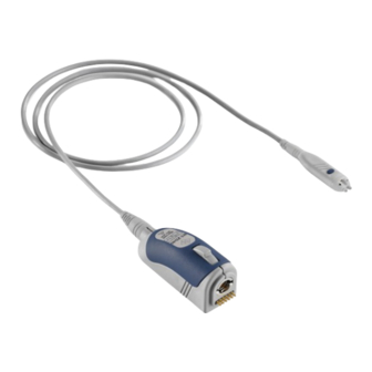
® Product description R&S RT-ZD40 Description of the probe 2.3.1 Probe head The small and lightweight probe head is designed for easy handling and high-per- formance measurements. The probe head is used for connecting the probe and the DUT. Different accessories for the signal and ground sockets allow the probe head to be connected to a wide range of DUTs. -
Page 13: Probe Box
® Product description R&S RT-ZD40 Accessories and items 2.3.2 Probe box The probe box connects the probe and the oscilloscope via the Rohde & Schwarz probe interface. The Rohde & Schwarz probe interface contains a male precision 7 mm (276 mil) BNC connector and six pogo pin connectors. This interface pro- vides the required supply voltage and is also used to transmit analog signals and digital data simultaneously. -
Page 14: Accessories Supplied
® Product description R&S RT-ZD40 Accessories and items Figure 2-1: Available accessories The R&S RT-ZA15 external attenuator is not a accessory of the R&S RT-ZD40. Putting the R&S RT-ZA15 on the R&S RT-ZD40 can damage both parts mechani- cally. 2.4.1 Accessories supplied The following table shows the accessories supplied with the R&S RT‑ZD40 differ- ential probe. - Page 15 ® Product description R&S RT-ZD40 Accessories and items Table 2-1: Accessories supplied Item Quantity Description Signal pin, solder-in Socket adapter, variable spacing Browser adapter, rigid Browser adapter, spring- loaded Lead, 6 cm / 2.4 in Lead, 15 cm / 5.9 in Mini clip Micro clip User Manual 1410.5363.02 ─...
-
Page 16: Optional Accessories
® Product description R&S RT-ZD40 Accessories and items Item Quantity Description Marker band kit Carrying case with foam inlay For a list of spare parts, see Chapter 5.7, "Spare parts", on page 48. 2.4.2 Optional accessories If the delivered accessories do not meet individual customer requirements, Rohde &... -
Page 17: Service Accessories
® Product description R&S RT-ZD40 Accessories and items Table 2-4: Optional adapters Accessories Items Quantity R&S RT‑ZA9 probe box to N / USB adapter The adapter connects the R&S RT‑ZD40 differ- ential probe to any other oscilloscope or any other measurement instrument (e.g. a network or spectrum analyzer). - Page 18 ® Product description R&S RT-ZD40 Accessories and items Table 2-5: Service accessories Item Description R&S RT-ZK2 The service kit is used to calibrate the probe, to do perfor- mance tests, and for servicing. The service kit includes all adapters and accessories to connect the probe to the required measuring instruments.
-
Page 19: Connecting The Probe
® Connecting the probe R&S RT-ZD40 Connecting the probe to the oscilloscope Connecting the probe Handling the probe The R&S RT‑ZD40 can withstand a moderate amount of physical and electrical stress. To avoid damage, treat the probe with care: ● Handle the probe by the probe head or probe box. ●... -
Page 20: Identification Of The Probe
® Connecting the probe R&S RT-ZD40 Identification of the probe Connect the probe box (1) to the Rohde & Schwarz probe interface of the oscilloscope (2). The probe snaps in when connected properly to the port. Figure 3-1: Connecting the probe to the Rohde & Schwarz oscilloscope ►... -
Page 21: Connecting The Probe To The Dut
® Connecting the probe R&S RT-ZD40 Connecting the probe to the DUT The complete probe information is shown in the probe settings dialog. For more information, refer to the user manual of your oscilloscope. Connecting the probe to the DUT This chapter describes the different ways of connecting the probe to the DUT. - Page 22 ® Connecting the probe R&S RT-ZD40 Connecting the probe to the DUT Pins Signal pin, solder-in The fine wires on the pins are best suited to making secure contact with small contact points, such as SMT components or IC pins. ●...
- Page 23 ® Connecting the probe R&S RT-ZD40 Connecting the probe to the DUT Socket adapter The socket adapter is designed to plug the probe onto pin strips, or for the connection of standard accessories. Distance range: 2 mm to 5.08 mm (80 mil to 200 mil) The sockets are compatible with 0.64 mm (25 mil) square pins and 0.6 mm to 0.8 mm...
- Page 24 ® Connecting the probe R&S RT-ZD40 Connecting the probe to the DUT Leads and clips Short and long lead The lead provides a flexible connection to the DUT. It is plugged onto a pin on the DUT and connected to the signal sockets or the ground socket. In addition, you can use micro and mini clips with the leads.
- Page 25 ® Connecting the probe R&S RT-ZD40 Connecting the probe to the DUT Micro clip The micro clip is designed for probing IC pins and thin wires in fine-pitch applications. ● Clamp the micro clip to a pin. ● Connect it directly to the signal socket using a socket adapter, or use a lead to connect it to the signal adapter or the ground socket.
-
Page 26: Features And Characteristics Of R&S Rt-Zd40 Probes
® Features and characteristics of R&S RT‑ZD40 probes R&S RT-ZD40 Zero adjustment Features and characteristics of R&S RT‑ZD40 probes Zero adjustment The zero error can impair the measurement results, therefore, correct the zero error if necessary. The zero error of the probe itself is very small. However, differences in DUT and oscilloscope ground levels can cause larger zero errors visible on the oscilloscope's screen. -
Page 27: Micro Button
® Features and characteristics of R&S RT‑ZD40 probes R&S RT-ZD40 R&S ProbeMeter Micro button The micro button provides easy and quick access to important functions of the Rohde & Schwarz oscilloscope. After a function has been assigned, pressing the micro button remotely controls this specific function on the base unit. For exam- ple, "Run continuous"... -
Page 28: Offset Compensation
® Features and characteristics of R&S RT‑ZD40 probes R&S RT-ZD40 Offset compensation ● Independent of oscilloscope settings for position, vertical scale, horizontal scale, and trigger. ● Unique way to detect unexpected or inadmissible common mode voltages, e.g. bias points - measurement of common mode DC voltages without recon- necting the probe. -
Page 29: Common Mode Offset
® Features and characteristics of R&S RT‑ZD40 probes R&S RT-ZD40 Offset compensation Figure 4-1: Differential offset compensation for a single-ended measurement (negative ‑ ZD40 input connected to ground) using an R&S RT There are several ways to set the offset compensation: ●... - Page 30 ® Features and characteristics of R&S RT‑ZD40 probes R&S RT-ZD40 Offset compensation Figure 4-2: Common mode (CM) offset compensation for a differential measurement If the input signals fit into the operating voltage window of the R&S RT‑ZD40, it is not necessary to set a common mode offset compensation. The R&S RT‑ZD40 measures only differential input signals.
-
Page 31: Characteristics Of Differential Probes
® Features and characteristics of R&S RT‑ZD40 probes R&S RT-ZD40 Characteristics of differential probes Characteristics of differential probes A differential probe has three sockets: the positive signal socket (+), the negative signal socket (-), and the ground socket. Figure 4-3: Input voltages on a differential probe Multiple input voltages can be defined for a differential probe: ●... -
Page 32: Common Mode Rejection Ratio (Cmrr)
® Features and characteristics of R&S RT‑ZD40 probes R&S RT-ZD40 Characteristics of differential probes The output voltage V , which is displayed on the base unit, is obtained by super- imposing the voltages generated from the differential mode input voltage and from the common mode input voltage: ... -
Page 33: Dynamic Range And Operating Voltage Window
® Features and characteristics of R&S RT‑ZD40 probes R&S RT-ZD40 Characteristics of differential probes ● Probing on ground-referenced signals. In this case, the common mode com- ponent is always equal to half of the input voltage. 4.5.2 Dynamic range and operating voltage window Two separate specifications are necessary to characterize the permissible input voltage range of a differential voltage probe: ●... -
Page 34: Ground Connection
® Features and characteristics of R&S RT‑ZD40 probes R&S RT-ZD40 Measurement principles Signal clipping Only differential input signals are detected by the probe and displayed by the base unit. Common mode signals are suppressed by the probe. Therefore, the user does not initially recognize that the operating voltage window is exceeded owing to inadmissible common mode voltages. - Page 35 ® Features and characteristics of R&S RT‑ZD40 probes R&S RT-ZD40 Measurement principles ● Low loading of the input signal: Every probe is a load for the signal to be measured. The signal to be mea- sured changes when the probe is connected. A good probe causes only a minimum change to the signal, so that the function of the DUT is not adversely affected.
-
Page 36: Signal Integrity Of The Transferred Signal
® Features and characteristics of R&S RT‑ZD40 probes R&S RT-ZD40 Measurement principles Table 4-1: Designations Abbreviation Description Differential voltage between the test point without probe connected Differential voltage at the test point with probe connected, corre- sponds to the input voltage of the probe Differential source resistance of the DUT Differential load resistance of the DUT Probe-specific input resistance... - Page 37 ® Features and characteristics of R&S RT‑ZD40 probes R&S RT-ZD40 Measurement principles ‑ ZD40 Figure 4-6: Amplitude frequency response of the R&S RT The bandwidth: ● Specifies the maximum frequency at which a purely sinusoidal signal is still transferred at 70 % (–3 dB) of its amplitude. ●...
- Page 38 ® Features and characteristics of R&S RT‑ZD40 probes R&S RT-ZD40 Measurement principles ‑ ZD40 Figure 4-7: Step response of the R&S RT 4.6.1.2 Connection inductance The connection inductance L is caused by connecting the probe to the DUT. In contrast to the probe-specific bandwidth, the connection inductance mainly depends on the selected type.
- Page 39 ® Features and characteristics of R&S RT‑ZD40 probes R&S RT-ZD40 Measurement principles proportion ≈ resonance proportion Figure 4-8: Ground connection and connection inductance using the example of R&S RT- ZD10/20/30 Table 4-2 shows different types of connections between the probe and DUT and the associated connection inductance L .
- Page 40 ® Features and characteristics of R&S RT‑ZD40 probes R&S RT-ZD40 Measurement principles User Manual 1410.5363.02 ─ 06...
-
Page 41: Signal Loading Of The Input Signal
® Features and characteristics of R&S RT‑ZD40 probes R&S RT-ZD40 Measurement principles 4.6.1.3 CMRR The CMRR is very good for low-frequency signals, but it continuously decreases for higher frequencies. Therefore, the CMRR is usually specified as a function of frequency. Figure 4-9 shows a typical CMRR for an R&S RT‑ZD40 differential probe with a very symmetrical connection to the DUT. - Page 42 ® Features and characteristics of R&S RT‑ZD40 probes R&S RT-ZD40 Measurement principles between its positive (+) and the negative (-) signal socket. The resulting input impedance versus frequency is indicated in Figure 4-10. ‑ ZD40 probe as a Figure 4-10: Magnitude of the differential input impedance of the R&S RT function of frequency The differential input impedance varies greatly versus the frequency and is defined by the following values:...
- Page 43 ® Features and characteristics of R&S RT‑ZD40 probes R&S RT-ZD40 Measurement principles RF resistance R The RF resistance R determines the minimum input impedance and thus the maximum loading at very high frequencies above 1.0 GHz. Thus, the measure- ment result depends on the source impedance of the DUT. The RF resistance R prevents the input voltage from rising immediately to its final value in the case of fast transients.
-
Page 44: Probing Philosophy
® Features and characteristics of R&S RT‑ZD40 probes R&S RT-ZD40 Measurement principles The equivalent circuit diagram in Figure 4-5 can be used to determine the associ- ated input impedance. The Table 4-3 provides as an example the DC input resist- ance for several input signals. - Page 45 ® Features and characteristics of R&S RT‑ZD40 probes R&S RT-ZD40 Measurement principles If measurements are carried out in a 100 Ω (or a comparable) environment, the signal displayed on the oscilloscope is always a direct representation of the unloaded signal VS, see Figure 4-12.
-
Page 46: Maintenance And Service
® Maintenance and service R&S RT-ZD40 Contacting customer support Maintenance and service Like all Rohde & Schwarz products, Rohde & Schwarz probes and adapters are of high quality and require only minimum service and repair. However, if service or calibration is needed, contact your Rohde & Schwarz service center. Return a defective product to the Rohde &... -
Page 47: Returning For Servicing
® Maintenance and service R&S RT-ZD40 Calibration interval Figure 5-1: QR code to the Rohde & Schwarz support page Returning for servicing Use the original packaging to return your R&S RT‑ZD40 to your Rohde & Schwarzservice center. A list of all service centers is available on: www.services.rohde-schwarz.com If you cannot use the original packaging, consider the following: 1. -
Page 48: Storage And Transport
® Maintenance and service R&S RT-ZD40 Spare parts Storage and transport Protect the product against dust. Ensure that the environmental conditions, e.g. temperature range and climatic load, meet the values specified in the data sheet. Store the product in a shock-resistant case, e.g. in the shipping case. Unless otherwise specified in the data sheet, the maximum transport altitude with- out pressure compensation is 4500 m above sea level. - Page 49 ® Maintenance and service R&S RT-ZD40 Spare parts Table 5-1: Accessories spare parts Pos Item Description Material Number Browser adapter, spring loaded 1417.0680.00 Browser adapter, rigid 1417.0673.00 Socket adapter, variable spacing 1417.0667.00 Lead, 6 cm / 2.4 in 1416.0128.00 Lead, 15 cm / 5.9 in 1416.0134.00 Mini clip 1416.0105.00...
- Page 50 ® Maintenance and service R&S RT-ZD40 Spare parts Pos Item Description Material Number Micro clip 1416.0111.00 Marker band kit 1416.0205.00 Signal pin, solder-in 1417.0838.00 Pogo pin Pogo pin connector, 6 pins 3584.6396.00 R&S RT-ZK2 R&S RT-ZK2 service kit 1410.5305.02 Table 5-2: Parts for ESD prevention Pos.
-
Page 51: Functional Check
® Functional check R&S RT-ZD40 Functional check The functional check confirms the basic operation of the R&S RT‑ZD40 differen- tial probe. The functional check is not suitable for verifying compliance with the probe specifications. 1. Connect the R&S RT‑ZD40 to a Rohde & Schwarz oscilloscope as described Chapter 3.2, "Connecting the probe to the oscilloscope", on page 19.
Need help?
Do you have a question about the R&S RT-ZD40 and is the answer not in the manual?
Questions and answers