Table of Contents
Advertisement
Quick Links
Advertisement
Table of Contents

Related Manuals for Rohde & Schwarz R&S RT-ZD40


Summary of Contents for Rohde & Schwarz R&S RT-ZD40
- Page 1 ® R&S RT-ZD40 Active Differential Probe User Manual (>:ÃÍ2) 1410536302...
- Page 2 ® This User Manual describes the following R&S RT-ZD models and options: ● R&S ® RT-ZD40 (1410.5205.02) © 2019 Rohde & Schwarz GmbH & Co. KG Mühldorfstr. 15, 81671 München, Germany Phone: +49 89 41 29 - 0 Fax: +49 89 41 29 12 164 Email: info@rohde-schwarz.com Internet:...
-
Page 3: Table Of Contents
® Contents R&S RT-ZD40 Contents 1 Product Description.............. 5 1.1 Key Features and Key Characteristics..........5 1.1.1 Key Characteristics................. 5 1.1.2 Key Features...................6 1.2 Unpacking....................7 1.2.1 Inspecting the Contents................7 1.3 Description of the Probe..............8 1.3.1 Probe Head.....................8 1.3.2 Probe Box....................9 1.4 Accessories and Items............... - Page 4 ® Contents R&S RT-ZD40 4 Characteristics of Differential Probes....... 27 4.1 Common Mode Rejection Ratio (CMRR)...........28 4.2 Dynamic Range and Operating Voltage Window......29 4.3 Ground Connection................30 5 Measurement Principles............. 31 5.1 Signal Integrity of the Transferred Signal.........33 5.1.1 Bandwidth..................... 33 5.1.2 Connection Inductance.................
-
Page 5: Product Description
® Product Description R&S RT-ZD40 Key Features and Key Characteristics Product Description Key Features and Key Characteristics The R&S RT-ZD40 is a differential probe with high input impedance. It is used for differential voltage measurements from DC to 4.5 GHz. Differential probes can be used for single-ended and differential applications. -
Page 6: Key Features
® Product Description R&S RT-ZD40 Key Features and Key Characteristics Bandwidth DC to 4.5 GHz Dynamic range ±5 V with ±5 V offset capability (differential input) 10 V AC (Vpp) Operating voltage window ±8 V with ±22 V common mode offset capability (each pin to GND) Available for R&S RT-ZD40 probes with serial number ≥... -
Page 7: Unpacking
® Product Description R&S RT-ZD40 Unpacking Data memory The probe has an integrated data memory, containing the individual probe correc- tion parameters (e.g. gain, delay, offset). These parameters are read out and pro- cessed by the Rohde & Schwarz oscilloscope. As a result, the probe offers a high degree of accuracy, and additional calibration procedures are not required. -
Page 8: Description Of The Probe
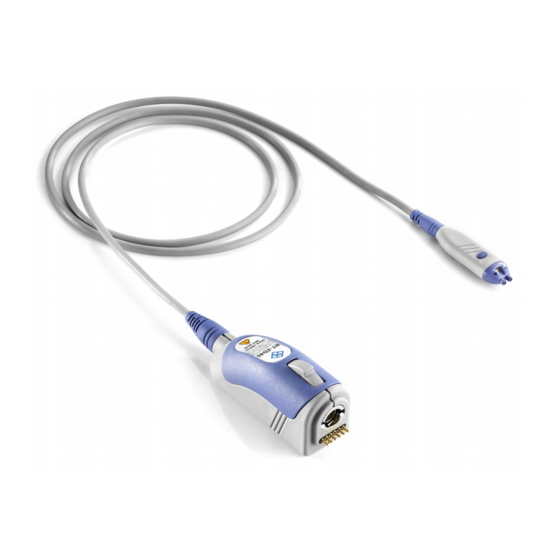
® Product Description R&S RT-ZD40 Description of the Probe Accessories supplied with the device are listed in Chapter 1.4.1, "Accessories Supplied", on page 11. Description of the Probe The probe consists of the probe head for connection to the DUT, the probe box for connection to the oscilloscope, and the probe cable. -
Page 9: Probe Box
® Product Description R&S RT-ZD40 Description of the Probe Special accessories for signal sockets The signal sockets of R&S RT-ZD40 have a special design to ensure opti- mal performance. The signal sockets are not compatible to standard acces- sories based on 0.64 mm (25 mil) square pins or 0.8 mm (35 mil) round pins. -
Page 10: Accessories And Items
® Product Description R&S RT-ZD40 Accessories and Items Accessories and Items The figure below shows all accessories that are available for the R&S RT-ZD40 differential probe. Figure 1-1: Available accessories The R&S RT-ZA15 external attenuator is not a accessory of the R&S RT-ZD40. Putting the R&S RT-ZA15 on the R&S RT-ZD40 can damage both parts mechani- cally. -
Page 11: Accessories Supplied
® Product Description R&S RT-ZD40 Accessories and Items 1.4.1 Accessories Supplied The following table shows the accessories supplied with the R&S RT-ZD40 differ- ential probe. Table 1-1: Accessories supplied Item Quantity Description Signal pin, solder-in Socket adapter, variable spacing Browser adapter, rigid Browser adapter, spring- loaded Lead, 6 cm / 2.4 in... -
Page 12: Optional Accessories
® Product Description R&S RT-ZD40 Accessories and Items Item Quantity Description Micro clip Marker band kit Carrying case with foam inlay For a list of spare parts, see Chapter 6.6, "Spare Parts", on page 44. 1.4.2 Optional Accessories If the delivered accessories do not meet individual customer requirements, Rohde &... -
Page 13: Service Accessories
® Product Description R&S RT-ZD40 Accessories and Items ‑ ZA6 lead set Table 1-4: R&S RT Item Quantity Description Lead, 6 cm / 2.4 in Contains short and long leads. Lead, 15 cm / 5.9 in ‑ ZA8 differential pin set Table 1-5: R&S RT Item Quantity... -
Page 14: Putting Into Operation
® Putting into Operation R&S RT-ZD40 Putting into Operation The probe is designed for usage with oscilloscopes that have a Rohde & Schwarz probe interface. Supported Rohde & Schwarz oscilloscopes are listed in the pro- be's data sheet. Read and observe the printed "Basic Safety Instructions" that are delivered with the probe. -
Page 15: Connecting The Probe To The Oscilloscope
® Putting into Operation R&S RT-ZD40 Connecting the Probe to the Oscilloscope During usage, the probe slightly heats up. Warming is normal behavior and not a sign of malfunction. Damage caused by electrostatic discharge Electrostatic discharge (ESD) can damage the electronic components of the probe and the instrument, and also the device under test (DUT). -
Page 16: Identification Of The Probe
® Putting into Operation R&S RT-ZD40 Using the Probe ► To disconnect the probe: a) Press and hold the release button (3). b) Pull the probe box away from the oscilloscope. Identification of the Probe When the probe is connected to the oscilloscope, the oscilloscope recognizes the probe and reads out the probe-specific parameters. -
Page 17: Micro Button
® Putting into Operation R&S RT-ZD40 Offset Compensation 4. Adjust the zero position of the waveform using the appropriate function of the oscilloscope ("AutoZero", "Zero Adjust" or similar). The waveform is set to 0 V on the horizontal centerline of the oscilloscope. 2.3.2 Micro Button The micro button provides easy and quick access to important functions of the... -
Page 18: Common Mode Offset
® Putting into Operation R&S RT-ZD40 Offset Compensation The differential offset function can compensate a DC voltage applied between the positive and the negative input socket. This is particularly helpful if a small single- ended signal with a large DC offset is measured with a differential probe, for example, with the negative input socket connected to ground. - Page 19 ® Putting into Operation R&S RT-ZD40 Offset Compensation for measurements on differential signals with high common mode levels, for example, current measurements using a shunt resistor. Figure 2-3: Common mode (CM) offset compensation for a differential measurement If the input signals fit into the operating voltage window of the R&S RT-ZD40, it is not necessary to set a common mode offset compensation.
-
Page 20: R&S Probemeter
® Putting into Operation R&S RT-ZD40 Offset Compensation If supported by the Rohde & Schwarz oscilloscope, you can set the "CM offset" in the probe settings on the instrument. For more details, see the oscilloscope's user manual. 2.4.3 R&S ProbeMeter The R&S ProbeMeter is an integrated voltmeter that measures DC voltages with higher precision compared to the oscilloscope's DC accuracy. - Page 21 ® Putting into Operation R&S RT-ZD40 Offset Compensation Common mode measurement range ±8 V + common mode offset compensa- tion setting. The R&S ProbeMeter enables the ground-referenced measurement of voltages. A difference in the ground levels of oscilloscope and DUT can cause an unwan- ted zero error.
-
Page 22: Connecting The Probe To The Dut
® Connecting the Probe to the DUT R&S RT-ZD40 Connecting the Probe to the DUT This chapter describes the different ways of connecting the probe to the DUT. In addition, the accessories supplied are described and their use is explained. In order to achieve optimum RF performance, the connections should always be as short as possible. - Page 23 ® Connecting the Probe to the DUT R&S RT-ZD40 Adapters To insert and adjust the adapters The socket and browser adapters each consist of two separate parts: a red one for the posi- tive socket, and the blue part for the negative socket.
- Page 24 ® Connecting the Probe to the DUT R&S RT-ZD40 Browser adapter, rigid and spring-loaded The browser adapter allows handheld probing with maximum convenience. Because it com- pensates for minor unevenness and move- ments, it can establish a firm contact to the test point.
- Page 25 ® Connecting the Probe to the DUT R&S RT-ZD40 Mini clip The mini clip is designed for probing large IC pins, wires and through-hole components. The mini clip is connected to the ground socket using a lead, or it is connected to the signal sockets using the socket adapter and a lead.
- Page 26 ® Connecting the Probe to the DUT R&S RT-ZD40 Micro clip The micro clip is designed for probing IC pins and thin wires in fine-pitch applications. The micro clip is connected to the ground socket using a lead, or it is connected to the signal sockets using the socket adapter directly or using a lead.
-
Page 27: Characteristics Of Differential Probes
® Characteristics of Differential Probes R&S RT-ZD40 Characteristics of Differential Probes A differential probe has three sockets: the positive signal socket (+), the negative signal socket (-), and the ground socket. Figure 4-1: Input voltages on a differential probe Multiple input voltages can be defined for a differential probe: ●... -
Page 28: Common Mode Rejection Ratio (Cmrr)
® Characteristics of Differential Probes R&S RT-ZD40 Common Mode Rejection Ratio (CMRR) The output voltage V , which is displayed on the base unit, is obtained by super- imposing the voltages generated from the differential mode input voltage and from the common mode input voltage: ... -
Page 29: Dynamic Range And Operating Voltage Window
® Characteristics of Differential Probes R&S RT-ZD40 Dynamic Range and Operating Voltage Window ● Probing on ground-referenced signals. In this case, the common mode com- ponent is always equal to half of the input voltage. Dynamic Range and Operating Voltage Window Two separate specifications are necessary to characterize the permissible input voltage range of a differential voltage probe: ●... -
Page 30: Ground Connection
® Characteristics of Differential Probes R&S RT-ZD40 Ground Connection Signal clipping Only differential input signals are detected by the probe and displayed by the base unit. Common mode signals are suppressed by the probe. There- fore, the user does not initially recognize that the operating voltage window is exceeded owing to inadmissible common mode voltages. -
Page 31: Measurement Principles
® Measurement Principles R&S RT-ZD40 Measurement Principles The R&S RT-ZD40 differential probe provides an electrical connection between the DUT and the oscilloscope. The probe transfers the voltage of the electrical signal tapped off the DUT to the oscilloscope, where it is displayed graphically. Although a probe has a wide variety of specifications, these specifications can be grouped into two classes of basic requirements: ●... - Page 32 ® Measurement Principles R&S RT-ZD40 Figure 5-1: Equivalent circuit model of the R&S RT-ZD40 probe Table 5-1: Designations Abbreviation Description Differential voltage between the test point without probe connected Differential voltage at the test point with probe connected, corre- sponds to the input voltage of the probe Differential source resistance of the DUT Differential load resistance of the DUT Probe-specific input resistance...
-
Page 33: Signal Integrity Of The Transferred Signal
® Measurement Principles R&S RT-ZD40 Signal Integrity of the Transferred Signal Signal Integrity of the Transferred Signal The following sections describe the effect that bandwidth, connection inductance and common mode rejection ratio have on signal integrity. 5.1.1 Bandwidth The bandwidth BW of a probe is one of its specific parameters. The bandwidth of the probe and the bandwidth of the base unit together form the system band- width. -
Page 34: Connection Inductance
® Measurement Principles R&S RT-ZD40 Signal Integrity of the Transferred Signal rise Figure 5-3 shows a typical step response of an R&S RT-ZD40 differential probe. In addition to bandwidth, a constant amplitude frequency response of the probe is decisive for high signal integrity. The Figure 5-2 shows the typical amplitude fre- quency response of an R&S RT-ZD40 differential probe. - Page 35 ® Measurement Principles R&S RT-ZD40 Signal Integrity of the Transferred Signal ● Must be as small as possible (short lead length) to maintain high signal integ- rity. proportion ≈ resonance proportion Figure 5-4: Ground connection and connection inductance using the example of R&S RT- ZD10/20/30 Table 5-2 shows different types of connections between the probe and DUT...
- Page 36 ® Measurement Principles R&S RT-ZD40 Signal Integrity of the Transferred Signal User Manual 1410.5363.02 ─ 05...
-
Page 37: Cmrr
® Measurement Principles R&S RT-ZD40 Signal Loading of the Input Signal 5.1.3 CMRR The CMRR is very good for low-frequency signals, but it continuously decreases for higher frequencies. Therefore, the CMRR is usually specified as a function of frequency. Figure 5-5 shows a typical CMRR for an R&S RT-ZD40 differential probe with a very symmetrical connection to the DUT. -
Page 38: Signal Loading For Differential Input Signals
® Measurement Principles R&S RT-ZD40 Signal Loading of the Input Signal 5.2.1 Signal Loading for Differential Input Signals Figure 5-1 presents an equivalent circuit model of an R&S RT-ZD40 differen- tial probe. The differential input impedance of the probe is equal to the impedance between its positive (+) and the negative (-) signal socket. - Page 39 ® Measurement Principles R&S RT-ZD40 Signal Loading of the Input Signal 5.2.1.2 Input Capacitance C The input capacitance C causes the input impedance to decrease in the medium-frequency range (100 kHz to 1.0 GHz). It affects the settling time of the input voltage in the case of fast transients.
-
Page 40: Signal Loading For Non-Differential Input Signals
® Measurement Principles R&S RT-ZD40 Probing Philosophy 5.2.2 Signal Loading for Non-Differential Input Signals As described in Chapter 4, "Characteristics of Differential Probes", on page 27, various types of input signals can be measured with a differential probe. Every type of input signal has an associated input impedance. ●... - Page 41 ® Measurement Principles R&S RT-ZD40 Probing Philosophy As a result, there are different opinions which signal is the better output of the probe: ● The initial signal that is not loaded by the probe (V ), and that corresponds to the signal at the test point without the probe being connected.
-
Page 42: Maintenance And Service
® Maintenance and Service R&S RT-ZD40 Contacting Customer Support Maintenance and Service Like all Rohde & Schwarz products, Rohde & Schwarz probes and adapters are of high quality and require only minimum service and repair. However, if service or calibration is needed, contact your Rohde & Schwarz service center. Return a defective product to the Rohde &... -
Page 43: Returning For Servicing
® Maintenance and Service R&S RT-ZD40 Returning for Servicing Europe, Africa, Middle East Phone +49 89 4129 12345 customersupport@rohde-schwarz.com North America Phone 1-888-TEST-RSA (1-888-837-8772) customer.support@rsa.rohde-schwarz.com Latin America Phone +1-410-910-7988 customersupport.la@rohde-schwarz.com Asia/Pacific Phone +65 65 13 04 88 customersupport.asia@rohde-schwarz.com China Phone +86-800-810-8228 / +86-400-650-5896 customersupport.china@rohde-schwarz.com Returning for Servicing Use the original packaging to return your R&S RT-ZD40 to your... -
Page 44: Calibration Interval
® Maintenance and Service R&S RT-ZD40 Spare Parts 4. Seal the box with tape. 5. Address the package to your nearest Rohde & Schwarz service center. Calibration Interval The recommended calibration interval for R&S RT-ZD40 differential probe is two years. For servicing, send the probe to your nearest Rohde & Schwarz service center (see Chapter 6.3, "Returning for Servicing",... - Page 45 ® Maintenance and Service R&S RT-ZD40 Spare Parts Pos Item Description Material Number Socket adapter, variable spacing 1417.0667.00 Lead, 6 cm / 2.4 in 1416.0128.00 Lead, 15 cm / 5.9 in 1416.0134.00 Mini clip 1416.0105.00 Micro clip 1416.0111.00 Marker band kit 1416.0205.00 Signal pin, solder-in 1417.0838.00...
- Page 46 ® Maintenance and Service R&S RT-ZD40 Spare Parts Table 6-2: Parts for ESD prevention Pos. Item Material number ESD wrist strap 0008.9959.00 ESD grounding cable 1043.4962.00 User Manual 1410.5363.02 ─ 05...
-
Page 47: Functional Check
® Functional Check R&S RT-ZD40 Functional Check The functional check confirms the basic operation of the R&S RT-ZD40 differen- tial probe. The functional check is not suitable for verifying compliance with the probe specifications. 1. Connect the R&S RT-ZD40 to a Rohde & Schwarz oscilloscope as described Chapter 2.1, "Connecting the Probe to the Oscilloscope", on page 15. -
Page 48: Index
® Index R&S RT-ZD40 Index Accessories ..........11 Micro button .........6, 17 AutoZero ..........16 N/USB adapter ........13 Bandwidth ..........6, 33 Operating voltage window ....... 29 Cleaning ..........42 Clipping ........... 30 Clips ............12 Pins CMRR ..........28, 37 Inserting and removing ....... 22 Common mode input voltage ....
Need help?
Do you have a question about the R&S RT-ZD40 and is the answer not in the manual?
Questions and answers