
Related Manuals for Rohde & Schwarz RT-ZS10


Summary of Contents for Rohde & Schwarz RT-ZS10
- Page 1 ® R&S RT-ZS10/10E/20/30 Active Voltage Probe User Manual (>:SO2) 1410353102 Version 08...
- Page 2 1410.3531.02 | Version 08 | R&S RT-ZS10/10E/20/30 ® Throughout this manual, products from Rohde & Schwarz are indicated without the symbol, e.g. ® ® R&S RT-ZS10/20/30 is indicated as R&S RT-ZS10/20/30, and R&S ProbeMeter is indicated as R&S Pro- beMeter.
-
Page 3: Table Of Contents
® Contents R&S RT-ZS10/10E/20/30 Contents 1 Safety and regulatory information........5 1.1 Safety instructions................5 1.2 Labels on the product................7 1.3 Warning messages in the documentation.......... 8 2 Product description...............9 2.1 Key features and key characteristics..........9 2.1.1 Key characteristics..................9 2.1.2 Key features..................10 2.1.3 R&S RT-ZS10E.................. - Page 4 ® Contents R&S RT-ZS10/10E/20/30 4.2 Offset compensation................28 4.3 Micro button..................29 4.4 R&S ProbeMeter..................29 4.5 Measurement principles..............30 4.5.1 Signal integrity of the transferred signal..........32 4.5.2 Signal loading of the input signal............37 4.5.3 Probing philosophy................40 5 Maintenance and service............ 42 5.1 Cleaning....................42...
-
Page 5: Safety And Regulatory Information
® Safety and regulatory information R&S RT-ZS10/10E/20/30 Safety instructions Safety and regulatory information The product documentation helps you to use the product safely and efficiently. Follow the instructions provided here and throughout the manual. Intended use The product is intended for the development, production and verification of elec- tronic components and devices in industrial, administrative, and laboratory envi- ronments. - Page 6 ® Safety and regulatory information R&S RT-ZS10/10E/20/30 Safety instructions sheet, manuals and the printed "Safety Instructions for Oscilloscopes and Acces- sories" document. If you are unsure about the appropriate use, contact Rohde & Schwarz customer service. Using the product requires specialists or specially trained personnel. These users also need sound knowledge of at least one of the languages in which the user interfaces and the product documentation are available.
-
Page 7: Labels On The Product
® Safety and regulatory information R&S RT-ZS10/10E/20/30 Labels on the product Consider that the rated voltage depends on the frequency. The voltage limita- tion curves or values are provided in the data sheet. ● Never cause any short circuits when measuring sources with high output cur- rents. -
Page 8: Warning Messages In The Documentation
® Safety and regulatory information R&S RT-ZS10/10E/20/30 Warning messages in the documentation Warning messages in the documentation A warning message points out a risk or danger that you need to be aware of. The signal word indicates the severity of the safety hazard and how likely it will occur if you do not follow the safety precautions. -
Page 9: Product Description
2.1.1 Key characteristics The key characteristics of the probe are the following: Bandwidth DC to 1 GHz (R&S RT-ZS10) DC to 1.5 GHz (R&S RT-ZS20) DC to 3 GHz (R&S RT-ZS30) Dynamic range ±8 V with ±12 V offset capability 16 V AC (V Maximum non-destructive input voltage ±30 V... -
Page 10: Key Features
In contrast to the R&S RT-ZS10, the R&S RT-ZS10E has a limited range of acces- sories, and does not offer offset compensation, micro button and R&S ProbeMe- ter. -
Page 11: Unpacking And Checking
R&S RT-ZS10/10E/20/30 Unpacking and checking In the following, the R&S RT-ZS10E and the R&S RT-ZS10 are equivalent, with the following exceptions: ● The R&S RT-ZS10E does not come with a carrying case or its contents. ● The R&S RT-ZS10E does not offer the offset compensation, micro button and R&S ProbeMeter functions. -
Page 12: Description Of The Probe
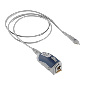
® Product description R&S RT-ZS10/10E/20/30 Description of the probe Accessories supplied with the probe are listed in Chapter 2.4.1, "Accessories supplied", on page 15. Description of the probe The probe consists of the probe head for connection to the DUT, the probe box for connection to the oscilloscope, and the probe cable. -
Page 13: Probe Box
® Product description R&S RT-ZS10/10E/20/30 Description of the probe (1) Signal socket (2) Ground socket (3) Micro button The accessories supplied for the probe head sockets are listed in Chapter 2.4.1, "Accesso- ries supplied", on page 15. Signal and ground sockets are compatible with 0.64 mm (25 mil) square pins and 0.6 mm to... -
Page 14: Accessories And Items
® Product description R&S RT-ZS10/10E/20/30 Accessories and items (1) Rohde & Schwarz probe interface with 7 mm (276 mil) coaxial connector and 6 pogo pins (2) Release knob Accessories and items The figure below shows all accessories that are available for the R&S RT‑ZS10/20/30 active voltage probe. -
Page 15: Accessories Supplied
® Product description R&S RT-ZS10/10E/20/30 Accessories and items 2.4.1 Accessories supplied The following table shows the accessories supplied with the R&S RT‑ZS10/20/30 active voltage probe. Table 2-1: Accessories supplied Item Quantity Description ZS10/20/30 ZS10E Signal pin Ground pin, pogo Ground pin, solderable, offset Ground adapter, square pin Lead, 6 cm / 2.4 in... -
Page 16: Optional Accessories
® Product description R&S RT-ZS10/10E/20/30 Accessories and items Item Quantity Description Micro clip Marker band kit Carrying case with foam inlay For a list of spare parts, see Chapter 5.7, "Spare parts", on page 44. 2.4.2 Optional accessories If the delivered accessories do not meet individual customer requirements, Rohde &... - Page 17 Micro clip Lead, 6 cm / 2.4 in Lead, 15 cm / 5.9 in Accessory box and vials Carrying case with foam inlay R&S RT-ZS10/20/30 User Manual R&S RT‑ZA3 pin set Signal pin Ground pin, pogo Ground pin, solderable, offset...
-
Page 18: Service Accessories
® Product description R&S RT-ZS10/10E/20/30 Accessories and items Table 2-4: Optional adapters Accessories Items Quantity R&S RT‑ZA9 probe box to N / USB adapter The adapter connects the R&S RT‑ZS10/20/30 active voltage probe to any other oscilloscope or any other measurement instrument (e.g. a net- work or spectrum analyzer). - Page 19 ® Product description R&S RT-ZS10/10E/20/30 Accessories and items Table 2-5: Service accessories Item Description R&S RT-ZK1 The service kit is used to calibrate the probe, to do perfor- mance tests, and for servicing. The service kit includes all adapters and accessories to connect the probe to the required measuring instruments.
-
Page 20: Connecting The Probe
® Connecting the probe R&S RT-ZS10/10E/20/30 Connecting the probe to the oscilloscope Connecting the probe Handling the probe The R&S RT‑ZS10/20/30 can withstand a moderate amount of physical and elec- trical stress. To avoid damage, treat the probe with care: ●... -
Page 21: Identification Of The Probe
® Connecting the probe R&S RT-ZS10/10E/20/30 Identification of the probe Connect the probe box (1) to the Rohde & Schwarz probe interface of the oscilloscope (2). The probe snaps in when connected properly to the port. Figure 3-1: Connecting the probe to the Rohde & Schwarz oscilloscope ►... -
Page 22: Connecting The Probe To The Dut
® Connecting the probe R&S RT-ZS10/10E/20/30 Connecting the probe to the DUT The complete probe information is shown in the probe settings dialog. For more information, refer to the user manual of your oscilloscope. Connecting the probe to the DUT This chapter describes the different ways of connecting the probe to the DUT. - Page 23 ® Connecting the probe R&S RT-ZS10/10E/20/30 Connecting the probe to the DUT Pins Signal pin The signal pin is held to the DUT to tap off the measurement signal. It fits into the signal socket and is designed for various applica- tions, e.g.
- Page 24 ® Connecting the probe R&S RT-ZS10/10E/20/30 Connecting the probe to the DUT The rigid ground pin is soldered to a test point on the DUT and provides a reliable and per- manent connection to the DUT. To protect the solder joint from excessive...
- Page 25 ® Connecting the probe R&S RT-ZS10/10E/20/30 Connecting the probe to the DUT Leads Short and long lead The lead provides a flexible connection to the DUT. It is plugged onto a pin on the DUT and can be used to connect either the signal socket or the ground socket.
- Page 26 ® Connecting the probe R&S RT-ZS10/10E/20/30 Connecting the probe to the DUT Micro clip The micro clip is designed for probing IC pins and thin wires in fine-pitch applications. The micro clip fits directly into the signal socket or the ground socket using a lead.
-
Page 27: Features And Characteristics Of Active Voltage Probes
® Features and characteristics of active voltage R&S RT-ZS10/10E/20/30 probes Zero adjustment Features and characteristics of active voltage probes Zero adjustment The zero error can impair the measurement results, therefore, correct the zero error if necessary. The zero error of the probe itself is very small. -
Page 28: Offset Compensation
® Features and characteristics of active voltage R&S RT-ZS10/10E/20/30 probes Offset compensation 4. Adjust the zero position of the waveform using the appropriate function of the oscilloscope ("AutoZero", "Zero Adjust" or similar). The waveform is set to 0 V on the horizontal centerline of the oscilloscope. -
Page 29: Micro Button
® Features and characteristics of active voltage R&S RT-ZS10/10E/20/30 probes R&S ProbeMeter ● Use the micro button to measure input signals with different DC offsets: assign "Offset to mean" to the micro button. See also Chapter 4.3, "Micro button", on page 29. -
Page 30: Measurement Principles
® Features and characteristics of active voltage R&S RT-ZS10/10E/20/30 probes Measurement principles ● Simple means of setting the oscilloscope's trigger level and vertical scaling if a waveform is not visible. ● Independent of oscilloscope settings for position, vertical scale, horizontal scale, and trigger. - Page 31 ® Features and characteristics of active voltage R&S RT-ZS10/10E/20/30 probes Measurement principles The high-frequency behavior of active probes is typically characterized in a 50 Ω measurement environment. The probe is connected to a 50 Ω line that is fed by a source with 50 Ω...
-
Page 32: Signal Integrity Of The Transferred Signal
® Features and characteristics of active voltage R&S RT-ZS10/10E/20/30 probes Measurement principles 4.5.1 Signal integrity of the transferred signal The following sections describe the effect that bandwidth and connection induc- tance have on signal integrity. 4.5.1.1 Bandwidth The bandwidth BW of a probe is one of its specific parameters. - Page 33 ® Features and characteristics of active voltage R&S RT-ZS10/10E/20/30 probes Measurement principles ● Specifies the transferable spectrum for other waveforms. E.g., with square wave signals, the fifth harmonic should still be within the bandwidth for a high signal integrity. ● Determines the minimum measurable signal rise time. The rise time t...
- Page 34 ® Features and characteristics of active voltage R&S RT-ZS10/10E/20/30 probes Measurement principles 4.5.1.2 Connection inductance The connection inductance L is caused by connecting the probe to the DUT. In contrast to the probe-specific bandwidth, the connection inductance mainly depends on the selected type.
- Page 35 ® Features and characteristics of active voltage R&S RT-ZS10/10E/20/30 probes Measurement principles User Manual 1410.3531.02 ─ 08...
- Page 36 ® Features and characteristics of active voltage R&S RT-ZS10/10E/20/30 probes Measurement principles Vout solderable pin Vout pogo pin 1000 Time in ps Figure 4-6: Step response of the R&S RT-ZS30 with a type 1 connection Vout ground lead 15 cm...
-
Page 37: Signal Loading Of The Input Signal
® Features and characteristics of active voltage R&S RT-ZS10/10E/20/30 probes Measurement principles Vout signal clip Vout signal lead Time in ns Figure 4-8: Step response of the R&S RT-ZS30 with a type 3 connection 4.5.2 Signal loading of the input signal The previous section dealt with the transfer function and step response of the probe. - Page 38 ® Features and characteristics of active voltage R&S RT-ZS10/10E/20/30 probes Measurement principles The resulting loading of a step signal at the input of the probe is given in Fig- 4-10. The connection inductance L has only a minor effect on the signal loading and is therefore not considered in the following.
- Page 39 ® Features and characteristics of active voltage R&S RT-ZS10/10E/20/30 probes Measurement principles init where τ 3 init 1000 Time in ps ‑ ZS10/20/30 probe at an effective source Figure 4-10: Signal loading caused by the R&S RT impedance of 25 Ω...
-
Page 40: Probing Philosophy
® Features and characteristics of active voltage R&S RT-ZS10/10E/20/30 probes Measurement principles RF resistance The RF resistance R determines the minimum input impedance and thus the maximum loading at high frequencies above 1.0 GHz. Thus, the measurement result depends on the source impedance of the DUT. The RF resistance prevents the input voltage from rising immediately to its final value for fast transients. - Page 41 ® Features and characteristics of active voltage R&S RT-ZS10/10E/20/30 probes Measurement principles Figure 4-11: Unloaded and loaded input signal and step response (for RT-ZS30) User Manual 1410.3531.02 ─ 08...
-
Page 42: Maintenance And Service
® Maintenance and service R&S RT-ZS10/10E/20/30 Contacting customer support Maintenance and service If service or calibration is needed, contact your Rohde & Schwarz service center. Return a defective product to the Rohde & Schwarz service center for diagnosis and exchange. -
Page 43: Returning For Servicing
® Maintenance and service R&S RT-ZS10/10E/20/30 Calibration interval Figure 5-1: QR code to the Rohde & Schwarz support page Returning for servicing Use the original packaging to return your R&S RT‑ZS10/20/30 to your Rohde & Schwarzservice center. A list of all service centers is available on: www.services.rohde-schwarz.com... -
Page 44: Storage And Transport
® Maintenance and service R&S RT-ZS10/10E/20/30 Spare parts Storage and transport Protect the product against dust. Ensure that the environmental conditions, e.g. temperature range and climatic load, meet the values specified in the data sheet. Store the product in a shock-resistant case, e.g. in the shipping case. - Page 45 ® Maintenance and service R&S RT-ZS10/10E/20/30 Spare parts Table 5-1: Accessories spare parts Pos. Item Description Material number Signal pin 1416.0005.00 Ground pin, pogo 1416.0034.00 Ground pin, solderable, off- 1416.0040.00 Ground adapter, square pin 1416.0063.00 Lead, 6 cm / 2.4 in 1416.0128.00...
- Page 46 ® Maintenance and service R&S RT-ZS10/10E/20/30 Spare parts Pos. Item Description Material number Pogo pin Pogo pin connector, 6 pins 3584.6396.00 R&S RT-ZK1 R&S RT-ZK1 service kit 1410.5157.02 Table 5-2: Parts for ESD prevention Pos. Item Material number ESD wrist strap 0008.9959.00...
-
Page 47: Functional Check
® Functional check R&S RT-ZS10/10E/20/30 Functional check The functional check confirms the basic operation of the R&S RT‑ZS10/20/30 active voltage probe. The functional check is not suitable for verifying compliance with the probe specifications. 1. Connect the R&S RT‑ZS10/20/30 probe to a Rohde & Schwarz oscilloscope as described in Chapter 3.2, "Connecting the probe to the... -
Page 48: Index
® Index R&S RT-ZS10/10E/20/30 Index Accessories ..........15 Offset compensation ....... 28 Spare parts ......... 44 Usage ..........22 Adapter ............ 18 Pins AutoZero ..........27 Usage ..........23 Probe Connection ..........20 Bandwidth ..........9, 32 Probe box ..........13 Probe head ..........12 Probe identification ........
Need help?
Do you have a question about the RT-ZS10 and is the answer not in the manual?
Questions and answers