Table of Contents
Advertisement
Quick Links
Cover
PG-FP5 V2.17
Flash Memory Programmer
All information contained in these materials, including products and product specifications,
represents information on the product at the time of publication and is subject to change by
Renesas Electronics Corporation without notice. Please review the latest information published
by Renesas Electronics Corporation through various means, including the Renesas Electronics
Corporation website (http://www.renesas.com).
User's Manual
: Common
Rev.5.00 Mar 2019
Advertisement
Table of Contents

Related Manuals for Renesas PG-FP5 V2.17


Summary of Contents for Renesas PG-FP5 V2.17
- Page 1 All information contained in these materials, including products and product specifications, represents information on the product at the time of publication and is subject to change by Renesas Electronics Corporation without notice. Please review the latest information published by Renesas Electronics Corporation through various means, including the Renesas Electronics Corporation website (http://www.renesas.com).
- Page 2 11. This document shall not be reprinted, reproduced or duplicated in any form, in whole or in part, without prior written consent of Renesas Electronics.
-
Page 3: Preface
Document number PG-FP5 V2.17 Flash Memory Programmer User's Manual Common This manual PG-FP5 V2.17 Flash Memory Programmer User's Manual RL78, 78K, V850, RX100, RX200, R20UT2923E RX61x, RX62x, RX63x, R8C, SuperH PG-FP5 V2.17 Flash Memory Programmer User's Manual RH850, RX64x, RX65x, RX66x,... -
Page 4: Important
(2) In no event shall Renesas Electronics Corporation be liable for any consequence arising from the use of this product. - Page 5 Renesas or to a third party. (3) This user’s manual and this product are copyrighted, with all rights reserved by Renesas. This user’s manual may not be copied, duplicated or reproduced, in whole or part, without prior written consent from Renesas.
-
Page 6: Precautions For Safety
PG-FP5 V2.17 PREFACE Precautions for Safety This chapter describes the precautions which should be taken in order to use this product safely and properly. Be sure to read and understand this chapter before using this product. Contact us if you have any questions about the precautions described here. - Page 7 PG-FP5 V2.17 PREFACE WARNING Warnings for AC Power Supply: If the AC power cable of the optional AC adapter does not fit the receptacle, do not alter the AC power cable and do not plug it forcibly. Failure to comply may cause electric shock and/or fire.
- Page 8 PG-FP5 V2.17 PREFACE CAUTION Cautions to Be Taken for the AC Adapter: Use only the optional dedicated AC adapter for this product. Do not use the AC adapter for other equipment. Cautions to Be Taken for Turning On the Power: Observe the following specified order for the power-on and power-off procedures of the user system and this product.
- Page 9 After use the equipment cannot be disposed of as household waste, and the WEEE must be treated, recycled and disposed of in an environmentally sound manner. Renesas Electronics Europe GmbH can take back end of life equipment, register for this service at “http://www.renesas.eu/weee”.
-
Page 10: Table Of Contents
PG-FP5 V2.17 PREFACE Contents PREFACE ................................3 Important ..............................4 Precautions for Safety ..........................6 Contents ..............................10 Terminology .............................. 13 Term replacement ............................. 14 1. OVERVIEW..............................15 1.1. Features ............................15 1.2. Writing Quality ........................... 15 1.3. Supported Devices ..........................15 1.4. - Page 11 PG-FP5 V2.17 PREFACE 5.3. Equivalence Circuits .......................... 50 5.4. External Connection Example ......................52 6. USAGE COMMUNICATION COMMANDS ....................53 6.1. Starting the Communications Software ..................... 53 6.2. Command List ........................... 55 6.3. Description of Commands ......................... 57 6.4. Description of FP5 Control Commands ..................... 58 6.4.1.
- Page 12 PG-FP5 V2.17 PREFACE 6.5.24. sed command ........................96 6.5.25. sid command ......................... 96 6.5.26. sig command ......................... 97 6.5.27. slb command ......................... 97 6.5.28. spd command ........................98 6.5.29. stm command ........................98 6.5.30. sum command ........................99 6.5.31. vrf command ......................... 99 7.
-
Page 13: Terminology
File in which data in multiple flash areas generated by Flash Development Toolkit is integrated. Flash Development Toolkit Flash Development Toolkit is a software to write in the flash memory of the Renesas microcontroller with on-chip flash. For details, refer to the following websites. https://www.renesas.com/fdt R20UT2922EJ0500 Rev.5.00... -
Page 14: Term Replacement
PG-FP5 V2.17 PREFACE Term Meaning. INI file File in which settings of the programming GUI are stored. The file is saved when the programming GUI is closed. The file name is "FP5.ini". OCD security ID Abbreviation of the on-chip debug security ID. Security function for on-chip debugging of the microcontroller. -
Page 15: Overview
PG-FP5 V2.17 OVERVIEW 1. OVERVIEW The FP5 is a tool that erases, writes and verifies programs on a Renesas Electronics on-chip flash memory microcontroller on the target system. 1.1. Features • Compatible with remote operation for FP5 from an external control device •... -
Page 16: Package Components
PG-FP5 V2.17 OVERVIEW 1.4. Package Components The package of this product includes the items listed below. Check the items. Note that the package for the PG-FP5 does not include an AC adaptor. Purchase an adaptor separately (refer to 1.8 AC Adaptors for PG-FP5). - Page 17 PG-FP5 V2.17 OVERVIEW <Programming GUI operation> The following operations can be performed with the programming GUI. For USB connection, the USB driver must be installed. The settings on the host PC are saved in an INI file. • ESF file creation •...
-
Page 18: Operating Environment
PG-FP5 V2.17 OVERVIEW 1.6. Operating Environment 1.6.1. Hardware environment (1) Host PCs • PC/AT compatible • Equipped with USB 2.0 ports (compatible with 1.1) • Equipped with RS-232C serial ports 1.6.2. Software environment (1) OS (either of the following) •... -
Page 19: Hardware Specifications
PG-FP5 V2.17 OVERVIEW 1.7. Hardware Specifications Table 1.2 Hardware Specifications Hardware Items Specifications FP5 main Operating power Supplied via AC adaptor (15 V) unit supply Temperature: ±0 to +40°C Operating environment ccondition Humidity: 10% to 80% RH (no condensation) Temperature: −15 to +60°C... -
Page 20: Ac Adaptors For Pg-Fp5
HCUHEX files are files that are required when ordering flash memory products whose flash memories are pre-written by Renesas Electronics. HCUHEX files are generated by the HEX Consolidation Utility (HCU), after which they must be verified on a flash memory programmer before being submitted. The PG-FP5 handles HCUHEX files as master data, and can therefore be used to check the written data and the option data settings. -
Page 21: Regulatory Compliance Notices
European Union only: This equipment (including all accessories) is not intended for household use. After use the equipment cannot be disposed of as household waste. Renesas Electronics Europe GmbH offers to take back the equipment. All you need to do is register at http://www.renesas.eu/weee. - Page 22 PG-FP5 V2.17 OVERVIEW EMC regulation (FCC) FCC Certifications: Note: This equipment has been tested and found to comply with the limits for a Class A digital device, pursuant to part 15 of the FCC Rules. These limits are designed to provide reasonable protection against harmful interference when the equipment is operated in a commercial environment.
-
Page 23: Hardware Configuration
PG-FP5 V2.17 HARDWARE CONFIGURATION 2. HARDWARE CONFIGURATION This chapter explains the hardware configuration. 2.1. System Configuration The FP5 system configuration is as shown in the diagram below. Serial cable USB cable AC adaptor Host PC External control devices Target cable... -
Page 24: Gnd Cable
PG-FP5 V2.17 HARDWARE CONFIGURATION 2.1.6. GND cable To reinforce the GND, use a GND cable to connect the FP5 GND connector and the signal GND of the target system or program adaptor. For details on the GND cable specifications, refer to 7 CONNECTORS AND CABLES. -
Page 25: Names And Functions On Main Unit
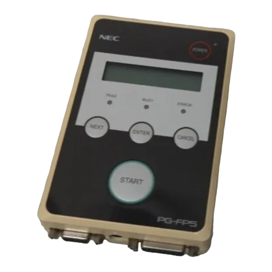
PG-FP5 V2.17 HARDWARE CONFIGURATION 2.2. Names and Functions on Main Unit This section describes the names and functions on the FP5 main unit. 2.2.1. FP5 control panel Indicators and buttons are laid out on the FP5 top. POWER LED POWER button... -
Page 26: Fp5 Connectors
PG-FP5 V2.17 HARDWARE CONFIGURATION 2.2.2. FP5 connectors The power supply connector, serial connector and USB connector are laid out on the host interface side. The target connector, GND connector and remote connector are laid out on the target connector side. - Page 27 PG-FP5 V2.17 HARDWARE CONFIGURATION (1) Power supply connector Connect the power supply connector to the AC adaptor. For details on the power supply connector specifications, refer to 7 CONNECTORS AND CABLES. Note Do not use an AC adaptor other than that included with the PG-FP5.
-
Page 28: Software Installation
PG-FP5 V2.17 SOFTWARE INSTALLATION 3. SOFTWARE INSTALLATION This chapter explains the software installation. 3.1. Obtaining Software Download the programming GUI, USB driver, and FP5 parameter file (PR5 file) from the following Renesas Electronics website. URLs • Except for Europe area: https://www.renesas.com/pg-fp5 For Europe area: http://www.renesas.eu/update →... -
Page 29: Notes On Installation
C:\Program Files\Common Files\Renesas Electronics CubeSuite+\ (Windows is the 64-bit edition and the system drive is C:) C:\Program Files\Common Files (x86)\Renesas Electronics CubeSuite+\ (11) To change the folder of the installed tools, uninstall all the CS+ related software and the programming GUI for PG-FP5, and install them again. -
Page 30: Uninstallation
Open [Add or Remove Programs] on the Control Panel and uninstall this program. The names are GUI, USB driver [PG-FP5 Vx.xx] and [USB Driver x86T for Renesas MCU Tools] (or [USB Driver x64 for Renesas MCU Tools]). Parameter files (*.pr5), setting files (*.esf), and INI file (FP5.ini) are not deleted. -
Page 31: Installation Of Programming Gui
PG-FP5 V2.17 SOFTWARE INSTALLATION 3.4.2. Installation of programming GUI Run the downloaded executable file (PG-FP5_Package_Vxxx.exe). Perform installation, following the directions on the installer screen. 3.4.3. Installation of firmware update Install the latest firmware by using the latest programming GUI. Decompress the file to any folder. The firmware file “fp5_fw_vxxx.rec”... - Page 32 2. When a firmware of FP5 updates from V2.00 to V1.xx, a serial number of FP5 is erased. And, FP5 can't operate in USB1.1. In addition, the other functions don't have any problem. When FP5 revives, consult a Renesas Electronics sales representative or distributor. R20UT2922EJ0500 Rev.5.00...
- Page 33 PG-FP5 V2.17 SOFTWARE INSTALLATION (3) Some commands are sent to the FP5 and the update progress status is displayed in the action log window. The message “Firmware Update succeeds”, which indicates normal completion of firmware update, and “Restarting FP5..”, which is equivalent to [RESET] command processing, is automatically performed. The new version can then be checked as “Firmware Version Vx.xx”.
-
Page 34: Installation Of Fpga Update
PG-FP5 V2.17 SOFTWARE INSTALLATION 3.4.4. Installation of FPGA update Install the latest FPGA by using the latest programming GUI. Decompress the file to any folder. The FPGA file “fp5_fpga_vx.rec” will then be decompressed into the folder, so copy it to any folder. (“x” indicates the FPGA version.) - Page 35 PG-FP5 V2.17 SOFTWARE INSTALLATION (2) Click the OK button to continue FPGA update. The [Open FPGA file] dialog box is opened. Figure 3.7 [Open FPGA file] Dialog Box Select the FPGA file “fp5_fpga_vx.rec” and then click the Open button. Note Do not use an FP5 FPGA other than the one posted on the website;...
- Page 36 PG-FP5 V2.17 SOFTWARE INSTALLATION (3) Some commands are sent to the FP5 and the update progress status is displayed in the action log window. The message “FPGA Update succeeded”, which indicates normal completion of firmware update, and “FP5 Power will be switched OFF now..”, which is equivalent to processing when the POWER button is turned off, is...
- Page 37 PG-FP5 V2.17 SOFTWARE INSTALLATION (5) Click the [Programmer] menu on the menu bar and select [Setup host connection...]; the [Host Connection] dialog box will then be opened. Select the communication mode used and then click the OK button. Figure 3.9 [Setup host connection] Command Figure 3.10 [Host Connection] Dialog Box...
- Page 38 PG-FP5 V2.17 SOFTWARE INSTALLATION (6) Communication with the host PC is established. “FPGA Vx” is displayed in the action log window; thus, the version can be checked. Figure 3.11 Version Confirmation After FPGA Update Is Finished R20UT2922EJ0500 Rev.5.00 Page 38 of 163...
-
Page 39: Usage In Standalone Mode
PG-FP5 V2.17 USAGE IN STANDALONE MODE 4. USAGE IN STANDALONE MODE The FP5 has a standalone mode in which the FP5 by itself can execute the [Erase], [Program], and [Autoprocedure(E.P.)] commands without a host PC. This mode is useful for using the FP5 on the production line during mass production and for upgrading in the field. - Page 40 PG-FP5 V2.17 USAGE IN STANDALONE MODE On the main menu level, the FP5 shows the menu items that can be selected. On the submenu level, the first line in the message display shows the menu item and the second line shows the response from the FP5, if any.
-
Page 41: Standalone Operation Menu
PG-FP5 V2.17 USAGE IN STANDALONE MODE 4.3. Standalone Operation Menu In standalone mode, the programming environment of the target device can be checked and then programs can be written by using the commands explained in this section. 4.3.1. [Commands] menu The [Commands] menu provides various commands required for programming the target device. - Page 42 PG-FP5 V2.17 USAGE IN STANDALONE MODE Table 4.1 [Commands] Menu (2) Main Menu Submenu Description [Commands >] [Set Lock bits >] Pressing the ENTER button executes the [Set Lock bits] command. [Set OptionBytes >] Pressing the ENTER button executes the [Set Option bytes] command.
-
Page 43: Type Setting] Menu
PG-FP5 V2.17 USAGE IN STANDALONE MODE 4.3.2. [Type Setting] menu The [Type Setting] menu is used to check information (target device programming environment settings) contained in the ESF file downloaded to the FP5. The settings downloaded to the valid programming area are displayed. All the values displayed are those downloaded last time by the programming GUI. -
Page 44: Option Setting] Menu
PG-FP5 V2.17 USAGE IN STANDALONE MODE 4.3.3. [Option Setting] menu The [Option Setting] menu is used to check the command options and security settings currently set for the FP5. The settings downloaded to the valid programming area are displayed. All the values displayed are those downloaded last time by the programming GUI. - Page 45 PG-FP5 V2.17 USAGE IN STANDALONE MODE Table 4.3 [Option Setting] Menu (2) Main Menu Submenu Description [Option Setting >] [PRG disable ] Displays the setting of the [Disable Program] check box in the [Security flag settings] area on the [Advanced] tab in the Device Setup dialog box.
- Page 46 PG-FP5 V2.17 USAGE IN STANDALONE MODE Table 4.3 [Option Setting] Menu (3) [SetID x-y ] Displays the setting of the [Setting] box in the [ID code for authentication] area on the [Standard] tab in the Device Setup dialog box. If the [NEXT] x-y = 1-8 or 9-16 button is clicked, the display changes from SetID 1-8 to SetID 9-16.
-
Page 47: Voltage Setting] Menu
PG-FP5 V2.17 USAGE IN STANDALONE MODE 4.3.4. [Voltage Setting] menu The [Voltage Setting] menu is used to check the voltage level setting used when programming the target device currently connected to the FP5. The settings downloaded to the valid programming area are displayed. The settings cannot be changed using this menu. -
Page 48: Utility/Misc.] Menu
PG-FP5 V2.17 USAGE IN STANDALONE MODE 4.3.5. [Utility/Misc.] menu The [Utility/Misc.] menu is used to reset the FP5 main unit, tune the LCD contrast, check the firmware version, check the name and version of the PR5 file downloaded, check the name of the program file downloaded, and check the checksum of program files. -
Page 49: Usage The Remote Connector
PG-FP5 V2.17 USAGE THE REMOTE CONNECTOR 5. USAGE THE REMOTE CONNECTOR This chapter describes the use of the remote connector. The FP5 can be remote controlled by connecting the remote connector and external control device. Remote control can be used to operate and check writing and PASS/ERROR displays from the external control device. -
Page 50: Equivalence Circuits
PG-FP5 V2.17 USAGE THE REMOTE CONNECTOR Table 5.2 Programming Area and Banks BANK2 BANK1 BANK0 Programming area 0 Programming area 1 Programming area 2 Programming area 3 Programming area 4 Programming area 5 Programming area 6 Programming area 7 Note 1. - Page 51 PG-FP5 V2.17 USAGE THE REMOTE CONNECTOR 74LV126A Signal output Signal_BUSY(2),PASS(3),ERROR(4) 信号出力回路 circuit FP5_3.3V FP5_3.3V 74LV126A 4.7KΩ Signal_CANCEL(5),ENTER(6),NEXT(7) Self-test circuit セルフテスト回路 74LV126A Signal input 信号入力回路 circuit Button circuit User System ボタン回路 (a) BUSY, PASS, ERROR, CANCEL, ENTER, NEXT 74LV126A Signal output Signal_CONN 信号出力回路...
-
Page 52: External Connection Example
PG-FP5 V2.17 USAGE THE REMOTE CONNECTOR 5.4. External Connection Example A connection example with a remote connector, external switch and LED is shown. PASS 3 ERROR 4 BUSY 2 START 9 Figure 5.3 External Switch and LED Connection Example R20UT2922EJ0500 Rev.5.00... -
Page 53: Usage Communication Commands
POWER LED will light, and “Commands >” will be displayed on the message display. If the unit does not come on in the manner described above, then there may be a malfunction in the FP5, so consult a Renesas Electronics sales representative or distributor. R20UT2922EJ0500 Rev.5.00... - Page 54 PG-FP5 V2.17 USAGE COMMUNICATION COMMANDS (3) Start communications software Start communications software Check the COM port number with Device Manager. Figure 6.2 Checking the COM Port Number Settings Select the data transfer conditions listed below. Data transfer rate: 9600 bps, 19200 bps, 38400 bps, 57600 bps, 115200 bps...
-
Page 55: Command List
PG-FP5 V2.17 USAGE COMMUNICATION COMMANDS 6.2. Command List The following is a list of FP5 control commands and device commands. Table 6.1 List of FP5 Control Commands Command name Description autocon Selects and confirms automatic or manual execution of the processes, from “transition to flash memory programming mode”... - Page 56 PG-FP5 V2.17 USAGE COMMUNICATION COMMANDS Table 6.2 List of FP5 Device Commands Command name Description Executes the [Blank check] command. Executes the Configuration clear. Executes the processes from “transition to flash memory programming mode” to “signature verification”. dcon Executes the termination of the flash memory programming mode.
-
Page 57: Description Of Commands
PG-FP5 V2.17 USAGE COMMUNICATION COMMANDS 6.3. Description of Commands Each of the commands is described using the following format. Command name Presents an overview of the command. Input format Note Presents the input format for the command Description of the function Describes the function of the command. -
Page 58: Description Of Fp5 Control Commands
PG-FP5 V2.17 USAGE COMMUNICATION COMMANDS 6.4. Description of FP5 Control Commands This section will describe the FP5 control commands. 6.4.1. autocon command Selects and confirms automatic or manual execution of the processes, from “transition to flash memory programming mode” to “signature verification”, and “the termination of the flash memory programming mode”. -
Page 59: Brt Command
PG-FP5 V2.17 USAGE COMMUNICATION COMMANDS 6.4.2. brt command Confirms and changes the data transfer rate for serial communication with the host PC. Input format 'brt' ('9600' | '19200' | '38400' | '57600' | '115200') Description of the function This command can be used with its options to change the data transfer rate for serial communications with the host PC. -
Page 60: Conf Command
PG-FP5 V2.17 USAGE COMMUNICATION COMMANDS 6.4.3. conf command Displays a list of the information stored in the FP5 and changes the number of programming area sections. Input format 'conf' ('progarea' '4x4' | '8x2'' | '10/6' | '1x16') Description of the function Divides the programming area into eight, four, two, or one areas depending on the selected option. - Page 61 PG-FP5 V2.17 USAGE COMMUNICATION COMMANDS Command Screen output conf progarea 4x4 [If there are four sections before the command is executed] INFO: Same setting. Configuration is not changed. [If there are eight sections before the command is executed] INFO: New configuration has been set.
- Page 62 PG-FP5 V2.17 USAGE COMMUNICATION COMMANDS Command Screen output conf See below. Firmware Version Vx.xx Board H/W Vx, FPGA Vx Serial No.: xxxxxxxxxx Standard mode unsecured Number of Program areas: 4 Active Program Area: 0 Size of Program Areas (Code / Data):...
-
Page 63: Downprm Command
PG-FP5 V2.17 USAGE COMMUNICATION COMMANDS 6.4.4. downprm command Downloads the PR5 file. Input format 'downprm' Description of the function Downloads the PR5 file. After this command is executed, the PR5 file must be downloaded to the FP5 in ASCII format by using communications software. -
Page 64: Fcks Command
PG-FP5 V2.17 USAGE COMMUNICATION COMMANDS 6.4.6. fcks command Executes the programming GUI [File] menu -> [Checksum...] command. Input format 'fcks' <type> <(code)start> <(code)end> (<data_start> <data_end> (<UB_start> <UB_end>))) Description of the function Executes a similar function to the programming GUI [File] menu -> [Checksum...] command. -
Page 65: Files Command
PG-FP5 V2.17 USAGE COMMUNICATION COMMANDS 6.4.7. files command Displays the information concerning the program file that was downloaded to the FP5. Input format 'files' ('check') Description of the function If no options are used, then information (file name, creation date, size, checksum) concerning the program file downloaded to the FP5 is displayed. -
Page 66: Fpga_Up Command
PG-FP5 V2.17 USAGE COMMUNICATION COMMANDS 6.4.8. fpga_up command Updates the FPGA. Input format 'fpga_up' Description of the function Updates the FPGA version. After this command is executed, the FPGA file must be downloaded to the FP5 in ASCII format using communications software. If using HyperTerminal, select Transfer(T) -> Transfer text file(T)..., and then select the FPGA file. -
Page 67: Hex Command
PG-FP5 V2.17 USAGE COMMUNICATION COMMANDS 6.4.9. hex command Uploads the program file in Intel HEX format. Input format 'hex' ((<code_start address> <code_length>) (<data_start address> <data_length>) (<UB_start address> <UB_length>)) Description of the function If a program file has been downloaded to a valid programming area, executing this command will upload the program file in Intel HEX format. -
Page 68: Hlp Command
PG-FP5 V2.17 USAGE COMMUNICATION COMMANDS 6.4.10. hlp command Lists available commands with brief descriptions. Input format 'hlp' Description of the function Lists frequently-used commands with brief descriptions. Example of usage Command Screen output See below. -------------- Control commands -------------- downprm/downset : Download parameter/customer settings... -
Page 69: Lod Command
PG-FP5 V2.17 USAGE COMMUNICATION COMMANDS 6.4.11. lod command Downloads program files. Input format 'lod' ('add') ('fname="filename"') ('ftime="date and time"') Description of the function Downloads the program file to a valid programming area. After this command is executed, the program file must be downloaded to the FP5 in ASCII format using communications software. -
Page 70: Prm Command
PG-FP5 V2.17 USAGE COMMUNICATION COMMANDS 6.4.12. prm command Displays the information concerning the PR5 file and ESF file that were downloaded to the FP5. Input format 'prm' Description of the function Displays the information concerning the PR5 file and ESF file (PR5 file name, PR5 checksum, ESF file checksum) that were downloaded to all the programming areas of the FP5. -
Page 71: Pwr_Off Command
PG-FP5 V2.17 USAGE COMMUNICATION COMMANDS 6.4.14. pwr_off command Turns off the FP5 power supply. Input format 'pwr_off' ('now' | 'auto' ('off' | <time [minutes]>)) Description of the function Turns off the FP5 power supply. Adjusts the off timing by designating the options. If options are not used, then the user can see if automatic power supply off is enabled or disabled. -
Page 72: Res Command
PG-FP5 V2.17 USAGE COMMUNICATION COMMANDS 6.4.15. res command Resets FP5. Input format 'res' Description of the function Executes a function similar to the programming GUI [Programmer] menu -> [Reset] command. Example of usage Command Screen output FFFFFFF PPPPP 555555 55555... -
Page 73: Selftest Command
PG-FP5 V2.17 USAGE COMMUNICATION COMMANDS 6.4.17. selftest command Executes a self-test. Input format 'selftest' Description of the function Executes a function similar to the programming GUI [Programmer] menu -> [Self-Test] command. Example of usage Command Screen output selftest ***** CAUTION ***** Remove any plugs from Target- and Remote-Connector before starting. -
Page 74: Sound Command
PG-FP5 V2.17 USAGE COMMUNICATION COMMANDS 6.4.19. sound command Sets the buzzer. Input format 'sound' ('off' | 'on') Description of the function Sets the buzzer. “Enabled” or “disabled” is optionally designated. If no option is designated, the current setting is displayed. -
Page 75: Srec Command
PG-FP5 V2.17 USAGE COMMUNICATION COMMANDS 6.4.20. srec command Uploads the program file in Motorola HEX format. Input format 'srec' ((<code_start address> <code_length>) (<data_start address> <data_length>) (<UB_start address> <UB_length>)) Description of the function If a program file has been downloaded to a valid programming area, executing this command will upload the program file in Motorola HEX format. -
Page 76: Trc Command
PG-FP5 V2.17 USAGE COMMUNICATION COMMANDS 6.4.21. trc command Displays the communication information between the FP5 and target device. Input format 'trc' Description of the function Displays the communication information between the FP5 and target device stored in the FP5 trace memory. Up to 1024 lines can be stored. -
Page 77: Upset Command
PG-FP5 V2.17 USAGE COMMUNICATION COMMANDS 6.4.23. upset command Uploads the ESF file. Input format 'upset' Description of the function If the ESF file has been downloaded to a valid programming area, then executing this command will upload the ESF file. -
Page 78: Version_Up Command
PG-FP5 V2.17 USAGE COMMUNICATION COMMANDS 6.4.25. version_up command Updates the firmware. Input format 'version_up' Description of the function Upgrades the firmware. After this command is executed, the firmware file must be downloaded to the FP5 in ASCII format using communications software. If using HyperTerminal, select Transfer(T) -> Transfer text file(T)..., and then select the firmware file. - Page 79 PG-FP5 V2.17 USAGE COMMUNICATION COMMANDS <2> FP5 Selfprogramming Vx.xx Checking FLMD0 level.. OK. Erase flash.. OK. Blank check.. OK. Write flash..OK. Margin check.. OK. Verify..OK. Firmware Update succeeds. Restarting FP5.. FFFFFFF PPPPP 555555 55555 FFFFF PPPPP 5555 Firmware Version Vx.xx Board H/W Vx, FPGA Vx Serial No.:xxxxxxxxxx...
-
Page 80: Description Of The Fp5 Device Commands
PG-FP5 V2.17 USAGE COMMUNICATION COMMANDS 6.5. Description of The FP5 Device Commands This section describes the FP5 device commands. 6.5.1. bln command Executes [Blank check] command. Input format 'bln' Description of the function Executes a similar function to the programming GUI [Device] menu -> [Blank check] command. -
Page 81: Con Command
PG-FP5 V2.17 USAGE COMMUNICATION COMMANDS 6.5.3. con command Executes the processes from “transition to the flash memory programming mode” to “signature verification”. Input format 'con' Description of the function Executes the processes from “transition to the flash memory programming mode” to “signature verification”. In order to use this command, “manual”... -
Page 82: Ep/Epv Command
PG-FP5 V2.17 USAGE COMMUNICATION COMMANDS 6.5.5. ep/epv command Executes [Autoprocedure(E.P.)] command. Input format 'ep' or 'epv' Description of the function Executes a similar function to the programming GUI [Device] menu -> [Autoprocedure(E.P.)] command. Example of usage Command Status Status LED... -
Page 83: Ers Command
PG-FP5 V2.17 USAGE COMMUNICATION COMMANDS 6.5.6. ers command Executes [Erase] command. Input format 'ers' Description of the function Executes a similar function to the programming GUI [Device] menu -> [Erase] command. Example of usage Command Status Status LED Message display... -
Page 84: Gdi Command
PG-FP5 V2.17 USAGE COMMUNICATION COMMANDS 6.5.7. gdi command Get the information of blank check and flash option. Input format 'gdi' Description of the function Obtains the information set by executing the [Get Flash options] command on the [Device] menu of the programming GUI. - Page 85 PG-FP5 V2.17 USAGE COMMUNICATION COMMANDS Command protection: xx ID code : ID code (ID0,ID1,…,ID15) Lock Bits: CF1: Lock Bits of Code Flash-1 * CF2: Lock Bits of Code Flash-2 * UB: Lock Bit of User Boot * OTP flags: CF1: OTP of Code Flash-1 *...
-
Page 86: Ged Command
PG-FP5 V2.17 USAGE COMMUNICATION COMMANDS 6.5.8. ged command Get the information of endian. Input format 'ged' Description of the function Get the information of endian. Example of usage Command Status Status LED Message display Screen output Display after executing the... -
Page 87: Glb Command
PG-FP5 V2.17 USAGE COMMUNICATION COMMANDS 6.5.10. glb command Get the lock bit. Input format 'glb' Description of the function Get the lock bit. Example of usage Command Status Status LED Message display Screen output Display after executing the PASS Returns to the display See below. -
Page 88: Gob Command
PG-FP5 V2.17 USAGE COMMUNICATION COMMANDS 6.5.11. gob command Get the information of option byte. Input format 'gob' Description of the function Obtains the information set by executing the [Set Option bytes] command on the [Device] menu of the programming GUI. -
Page 89: Gos Command
PG-FP5 V2.17 USAGE COMMUNICATION COMMANDS 6.5.13. gos command Get the information of flash option. Input format 'gos' Description of the function Obtains the information set by executing the [Get Flash options] command on the [Device] menu of the programming GUI. -
Page 90: Got Command
PG-FP5 V2.17 USAGE COMMUNICATION COMMANDS 6.5.14. got command Get the information of OTP. Input format 'got' Description of the function Get the information of OTP. Example of usage Command Status Status LED Message display Screen output Display after executing the... -
Page 91: Gsc Command
PG-FP5 V2.17 USAGE COMMUNICATION COMMANDS 6.5.15. gsc command Get the information of security. Input format 'gsc' Description of the function Obtains the information set by executing the [Set Security] command on the [Device] menu of the programming GUI. Example of usage... -
Page 92: Idc Command
PG-FP5 V2.17 USAGE COMMUNICATION COMMANDS 6.5.17. idc command Executes the ID code setting. Input format 'idc' Description of the function Executes the ID code setting. Example of usage Command Status Status LED Message display Screen output Display after executing the... -
Page 93: Otp Command
PG-FP5 V2.17 USAGE COMMUNICATION COMMANDS 6.5.19. otp command Executes the OTP setting. Input format 'otp' Description of the function Executes the OTP setting. Example of usage Command Status Status LED Message display Screen output Display after executing the PASS Returns to the display... -
Page 94: Read Command
PG-FP5 V2.17 USAGE COMMUNICATION COMMANDS 6.5.21. read command Executes [Read] command. Input format 'read' ('hex' | 'srec') (<start_address> <end_address>) Description of the function Executes a similar function to the programming GUI [Device] menu -> [Read] command. hex: Executes [Read] with the Intel HEX format. -
Page 95: Rsc Command
PG-FP5 V2.17 USAGE COMMUNICATION COMMANDS 6.5.22. rsc command Executes the Security Release command. Input format 'rsc' Description of the function Executes the Security Release command. Example of usage Command Status Status LED Message display Screen output Display after executing the... -
Page 96: Sed Command
PG-FP5 V2.17 USAGE COMMUNICATION COMMANDS 6.5.24. sed command Executes the endian setting. Input format 'sed' Description of the function Executes the endian setting. Example of usage Command Status Status LED Message display Screen output Display after executing the PASS Returns to the display... -
Page 97: Sig Command
PG-FP5 V2.17 USAGE COMMUNICATION COMMANDS 6.5.26. sig command Executes [Signature read] command. Input format 'sig' Description of the function Executes a similar function to the programming GUI [Device] menu -> [Signature read] command. Example of usage Command Status Status LED... -
Page 98: Spd Command
PG-FP5 V2.17 USAGE COMMUNICATION COMMANDS 6.5.28. spd command Executes the disable serial programming setting. Input format 'spd' Description of the function Executes the disable serial programming setting. Example of usage Command Status Status LED Message display Screen output Display after executing the... -
Page 99: Sum Command
PG-FP5 V2.17 USAGE COMMUNICATION COMMANDS 6.5.30. sum command Executes the programming GUI [Device] menu -> [Checksum] command. Input format 'sum' Description of the function Executes a similar function to the programming GUI [Device] menu -> [Checksum] command. Example of usage... -
Page 100: Connectors And Cables
PG-FP5 V2.17 CONNECTORS AND CABLES 7. CONNECTORS AND CABLES This chapter explains connectors and cables. 7.1. Power Supply Connector The power supply connector is laid out on the host interface side of the FP5. Power supply connector Figure 7.1 Power Supply Connector <FP5 Host Interface Side>... -
Page 101: Serial Connector
PG-FP5 V2.17 CONNECTORS AND CABLES 7.2. Serial Connector The serial connector (9-pin D-SUB male connector) is laid out on the host interface side of the FP5. Serial connector Figure 7.3 Serial Connector <FP5 Host Interface Side> Figure 7.4 Serial Connector Pin Assignment Table 7.1... -
Page 102: Usb Connector
PG-FP5 V2.17 CONNECTORS AND CABLES 7.3. USB Connector The mini-B type USB connector is laid out on the host interface side of the FP5. USB connector Figure 7.6 USB Connector <FP5 Host Interface Side> Part number of mini-B USB connector: UX60A-MB-5ST (made by Hirose Electric Co., Ltd.) 7.3.1. -
Page 103: Target Connector
PG-FP5 V2.17 CONNECTORS AND CABLES 7.4. Target Connector The target connector (15-pin HD-SUB female connector) is laid out on the target connector side of the FP5. Target connector Figure 7.8 Target Connector <FP5 Target Connector Side> Figure 7.9 Target Connector (15-Pin HD-SUB Female Connector) Pin Assignment Table 7.2... -
Page 104: Target Cable (16-Pin Type)
PG-FP5 V2.17 CONNECTORS AND CABLES 7.4.1. Target cable (16-pin type) The target cable (16-pin type) is a standard shielded cable approximately 42 centimeters long. The target cable is equipped with a 15-pin HD-SUB male connector and a 16-pin 2.54 mm pitch multipurpose female connector. - Page 105 PG-FP5 V2.17 CONNECTORS AND CABLES Note The following are the recommended connectors to be connected to 16-pin 2.54 mm pitch multipurpose female connectors. • HIF3FC-16PA-2.54DS (made by Hirose Electric Co., Ltd., right angle type) • HIF3FC-16PA-2.54DSA (made by Hirose Electric Co., Ltd., straight type) •...
-
Page 106: Target Cable (14-Pin Type)
PG-FP5 V2.17 CONNECTORS AND CABLES 7.4.2. Target cable (14-pin type) The target cable (14-pin type) is a standard shielded cable approximately 42 centimeters long. The target cable is equipped with a 15-pin HD-SUB male connector and a 14-pin 2.54 mm pitch multipurpose female connector. - Page 107 PG-FP5 V2.17 CONNECTORS AND CABLES Note The following are the recommended connectors to be connected to 14-pin 2.54 mm pitch multipurpose female connectors. • 7614-6002 (Sumitomo 3M Limited, straight type) • 2514-6002 (3M Limited, straight type) When using a self-made cable because the target cable cannot be used due to the target system specifications, the cable characteristics should be equivalent or higher than those of the target cable.
-
Page 108: Gnd Connector
PG-FP5 V2.17 CONNECTORS AND CABLES 7.5. GND Connector The banana jack GND connector is laid out on the target connector side of the FP5. GND connector Figure 7.16 GND Connector <FP5 Target Connector Side> Note Part number of GND connector (banana jack): PB4 (HIRSCHMANN) 7.5.1. -
Page 109: Notes On Target System Design
PG-FP5 V2.17 NOTES ON TARGET SYSTEM DESIGN 8. NOTES ON TARGET SYSTEM DESIGN This chapter explains the basic notes on the target system for writing to the flash memory in the target device, using the FP5. Target Device Pin Recommended Design •When connecting the FP5 output signal pins, refer to 9 SPECIFICATIONS OF TARGET... - Page 110 PG-FP5 V2.17 NOTES ON TARGET SYSTEM DESIGN Target Device Pin Recommended Design ¯¯¯¯¯¯ Correct connection <2>: RESET Target device FP5 RESET RESET Correct connection <3>: Target device FP5 RESET RESET Correct connection <4>: Target device FP5 RESET JUMPER RESET Correct connection <5>:...
- Page 111 PG-FP5 V2.17 NOTES ON TARGET SYSTEM DESIGN Target Device Pin Recommended Design I/O pins When a target device pin used by the FP5 is also connected to the input of an external device, and if that target device malfunctions, disconnect the external device as shown in the portion below enclosed in the dotted line or make it output high impedance like dotted line.
- Page 112 PG-FP5 V2.17 NOTES ON TARGET SYSTEM DESIGN The following are examples of interface circuits. Refer to the recommended design for the connection of pins in the target device. <1> 78K, V850 (SIO-H/S) Target connecter (16pin type) RESET Clock SI/RxD SO/TxD...
- Page 113 PG-FP5 V2.17 NOTES ON TARGET SYSTEM DESIGN <3> 78K, V850 (SIO - Internal single-power-supply flash memory microcontroller) Target device Target connecter(14pin type) 8. VDD 2. GND 12. GND Clock 14. Not used circuit Note1 4. FLMD0 FLMD0 (9. FLMD1) FLMD1 7.
- Page 114 PG-FP5 V2.17 NOTES ON TARGET SYSTEM DESIGN <5> 78K0S (Single-wire UART) Target connecter (16pin type) RESET Note SI/RxD SO/TxD FLMD1 Note FLMD0 RFU-1 RESET Target device Jumper Reset circuit Figure 8.5 Circuit Example for 78K0S (Single-wire UART) Note These pins do not need to be shorted when using the FP5. Short them if necessary.
- Page 115 PG-FP5 V2.17 NOTES ON TARGET SYSTEM DESIGN <7> I Target connecter (16pin type) RESET Clock SI/RxD SO/TxD circuit FLMD1 FLMD0 RFU-1 RESET Target device Jumper Reset circuit Figure 8.7 Circuit Example for I <8> 78K0 (TOOLCx, TOOLDx) Target connecter (16pin type)
- Page 116 PG-FP5 V2.17 NOTES ON TARGET SYSTEM DESIGN <9> V850E2 (Single-wire UART) Target device Target connecter(14pin type) 8. VDD 2. GND 12. GND Clock 14. Not used circuit Note2 4. FLMD0 FLMD0 (9. FLMD1) FLMD1 Note1 FPDTR 7. SO/TxD RESET 10. VDE...
- Page 117 PG-FP5 V2.17 NOTES ON TARGET SYSTEM DESIGN <11> RL78 family (VDD = EVDD) Target device Target connecter(14pin type) 8. VDD Note EVDD 9. FLMD1 2. GND 12. GND EVSS 14. Not used Note 1kΩ TOOL0 5. SI/RxD Note RESET 10. VDE 13.
- Page 118 PG-FP5 V2.17 NOTES ON TARGET SYSTEM DESIGN <13> RX family, SuperH family (SCI) Target device Target connecter(14pin type) 8. VDD Note4 Note4 2. GND Note4 Note4 Note4 Note6 12. GND EXTAL Clock 14. Not used XTAL circuit Note3 Note2 Note5 10.
- Page 119 PG-FP5 V2.17 NOTES ON TARGET SYSTEM DESIGN <14> R8C family Target device Target connecter(14pin type) 8. VDD 2. GND Note2 Note3 12. GND 4. FLMD0 6. RFU-1 10. VDE 14. Not used Note1 MODE 7. SO/TxD 13. RESET RESET Note4...
- Page 120 PG-FP5 V2.17 NOTES ON TARGET SYSTEM DESIGN <16> RH850 family (1 wire UART) Target connecter (14pin type) Target device [Note2] - - FPMD0 FLMD0 - (FPMD1) FLMD1 FPDR FPDR(JP0_0) 1K ~10KΩ - [Note1] - Clock - circuit RESET 100KΩ or more...
- Page 121 PG-FP5 V2.17 NOTES ON TARGET SYSTEM DESIGN <18> RH850 family (2 wire UART) Target connecter (14pin type) Target device [Note1] - - FPMD0 FPDT FPDT(FLSCI3TX) (FPMD1) FLMODE FPDR FPDR(FLSCI3RX) - - EXTAL Clock circuit - XTAL RESET 1K ~10KΩ [Note2] RESET 【Note3】...
-
Page 122: Specifications Of Target Interface Circuits
PG-FP5 V2.17 SPECIFICATIONS OF TARGET INTERFACE CIRCUITS 9. SPECIFICATIONS OF TARGET INTERFACE CIRCUITS This chapter describes the target interface specifications (signals connected to the FP5 and the target system), by using equivalent circuits. Note: The internal voltage regulator generates the FP5_VDD and FP5_VDD2 voltages. -
Page 123: Clk/Io5/Fpmd5
PG-FP5 V2.17 SPECIFICATIONS OF TARGET INTERFACE CIRCUITS 9.3. CLK/IO5/FPMD5 It is recommended to supply the target device operating clock from the target system. When supplying the target device operating clock from the FP5, communication may not be performed normally due to the waveform distortion caused by wiring of clock lines on the target system. -
Page 124: Vdd And Vdd2
PG-FP5 V2.17 SPECIFICATIONS OF TARGET INTERFACE CIRCUITS 9.5. V and V When supplying V and V from the target system, the FP5 internal power supply and the external voltage regulator is protected by a transistor. FP5_V FP5_V または or FP5_V FP5_V ト... -
Page 125: Troubleshooting
PG-FP5 V2.17 TROUBLESHOOTING 10. TROUBLESHOOTING This chapter explains troubleshooting. Note Using the self-testing function, the user can find out the reason why the FP5 does not operate normally, such as a defect in the FP5, or problems in other hardware. For how to use the tool, refer to each microcontroller edition 1.3.2 (6) [Self-Test] command. -
Page 126: Problems During Operation
Refer to 10.1 Problems During Startup and take appropriate action. [Cause 2] When “Renesas USB Development Tools” is expanded in the Device Manager while the FP5 is connected via a USB port, “Flash Programmer FP5” is not displayed. Alternatively, a “!” or “×” is attached. - Page 127 PG-FP5 V2.17 TROUBLESHOOTING (2) The following messages are displayed in the action log window and the flash memory programming mode cannot be entered. ERROR(E012):Connection or synchronization failed ERROR(E014):Connection or synchronization failed [Cause 1] The connection between the target system and FP5 may be incorrect.
- Page 128 PG-FP5 V2.17 TROUBLESHOOTING [Cause 6] UART communication may not be synchronized. [Action 6] When UART is used, communication may not be synchronized due to a baud rate error of the target device. In this case, change the CPU clock or baud rate, or change the communication channel to another communication mode.
-
Page 129: Maintenance And Warranty
PG-FP5 V2.17 MAINTENANCE AND WARRANTY 11. MAINTENANCE AND WARRANTY This chapter covers basic maintenance, warranty information, provisions for repair and the procedures for requesting a repair. 11.1. Maintenance (1) If dust or dirt collects on this product, wipe it off with a dry soft cloth. Do not use thinner or other solvents because these chemicals can cause the surface coating to separate. -
Page 130: How To Make Request For Repair
PG-FP5 V2.17 MAINTENANCE AND WARRANTY 11.4. How to Make Request for Repair If your product is found faulty, fill in a Repair Request Sheet downloadable from the following URL. And email the sheet and send the product to your local distributor. -
Page 131: Appendix A Messages
PG-FP5 V2.17 MESSAGES APPENDIX A MESSAGES This chapter explains the messages. A.1. Message Format Messages will be output in the error/warning dialog boxes, information dialog boxes, or action log window during programming GUI operation. Error messages will be displayed on the FP5 message display during standalone operation. -
Page 132: Error/Warning Dialog Boxes For Programming Gui Operation
PG-FP5 V2.17 MESSAGES A.2. Error/Warning Dialog Boxes for Programming GUI Operation Message Description E 1100 Communication within host PC and An error occurred in communication between the host FlashProgrammer is broken PC and the FP5. Check the cable connection and FP5 power supply. - Page 133 PG-FP5 V2.17 MESSAGES Message Description E 1501 This file is not valid. The file opened with the HEX Editor is invalid. E 1502 Caution: Data Flash access unit is DWORD. The data flash area can be accessed in double-word units, but an access was attempted in unsupported units.
- Page 134 PG-FP5 V2.17 MESSAGES Message Description E 1526 Error line : <line number> A data count error has occurred in line line-number. The program file format may be incorrect. Data Count error. Abort "Data Count Check" E 1527 Cannot open temporary file.
-
Page 135: Information Dialog Boxes For Programming Gui Operation
PG-FP5 V2.17 MESSAGES A.3. Information Dialog Boxes for Programming GUI Operation Message Description I 2100 Please setup host connection again. After FP5 reset, communication with FP5 was attempted but failed. Try [Programmer] - [Setup host connection] in the menu. I 2200 Please open 'Setup' form menu. - Page 136 PG-FP5 V2.17 MESSAGES Message Description I 2300 Value out of range. The set value of file checksum command is out of the valid ranges. The valid code flash range is 0-0x400000. The valid data flash range is 0x400000 to 0x420000.
- Page 137 PG-FP5 V2.17 MESSAGES Message Description − I 2500 Welcome to FP5 Manager! [Yes]:Continue to set FP5 Manager [No]:Return to Standard mode unsecured − I 2501 Initialize as shipment condition? Warning: After initialization all data and parameter settings in FP5 will be deleted.
-
Page 138: Error Messages Displayed In Fp5 Message Display
Freq. set failed Setting the Oscillator frequency Check if the oscillator frequency is allowed. If yes, failed. contact Renesas Electronics support desk. Baudrt. set fail Setting the communication baud Unsupported baud rate specified. Please consult the rate failed. - Page 139 Erase timed out The device may be damaged. Ers Timeset err Erase time setting error The PR5 file may contain invalid data. Contact Renesas Electronics. Blank chk failed Blank check failed The device connected is not empty. Use the ‘erase’...
- Page 140 Please change Setup (uncheck: V : On Target). FP5 int Vpp fail FP5 Power failure. Please contact Renesas Electronics support desk. FP5 int Vdd fail FP5 Power failure. Please contact Renesas Electronics support desk. FP5 int Vdd2 fail FP5 Power failure.
- Page 141 PG-FP5 V2.17 MESSAGES Message Error Condition Possible Workaround OTP Comm err Comm error during OTP set A communication problem occurred between the FP5 command. and target device. Try the operation again. Or, the device may be damaged. SID Comm err...
-
Page 142: Appendix B Supplementary Information
PG-FP5 V2.17 SUPPLEMENTARY INFORMATION APPENDIX B SUPPLEMENTARY INFORMATION This chapter covers supplementary information referred to by the user’s manual of the FP5. <HEX Editor> address +0 +1 +2 +3 +4 +5 +6 +7 +8 +9 +A +B +C +D +E +F... - Page 143 PG-FP5 V2.17 SUPPLEMENTARY INFORMATION /* The generator polynomial used for this table is */ /* x^32+x^26+x^23+x^22+x^16+x^12+x^11+x^10+x^8+x^7+x^5+x^4+x^2+x^1+x^0 */ /* according to Autodin/Ethernet/ADCCP protocol standards */ /* Binary: 0x04c11db7 */ const u32 CRC32_Tab [256]= { 0x00000000, 0x04c11db7, 0x09823b6e, 0x0d4326d9, 0x130476dc, 0x17c56b6b, 0x1a864db2, 0x1e475005,...
- Page 144 PG-FP5 V2.17 SUPPLEMENTARY INFORMATION ----------------------------- Thu Aug 02 14:11:46 2007 ------Start record file------ >ep Blank check Chip: ERROR(E051): Not blank, Erase needed. Erase Chip: PASS Program Chip: 100% PASS Erase,Program operation finished. > ------End record file------ > Thu Aug 02 14:12:03 2007 --------------------------- Figure B.3 Log File Example...
- Page 145 PG-FP5 V2.17 SUPPLEMENTARY INFORMATION /* The generator polynomial used for this table is: */ /* x^16+x^12+x^5+x^0 according to CCITT-16 standard. */ /* Binary: 0x1021 */ const uint16_t CRC16_Tab [256]= { 0x0000,0x1021,0x2042,0x3063,0x4084,0x50A5,0x60C6,0x70E7, 0x8108,0x9129,0xA14A,0xB16B,0xC18C,0xD1AD,0xE1CE,0xF1EF, 0x1231,0x0210,0x3273,0x2252,0x52B5,0x4294,0x72F7,0x62D6, 0x9339,0x8318,0xB37B,0xA35A,0xD3BD,0xC39C,0xF3FF,0xE3DE, 0x2462,0x3443,0x0420,0x1401,0x64E6,0x74C7,0x44A4,0x5485, 0xA56A,0xB54B,0x8528,0x9509,0xE5EE,0xF5CF,0xC5AC,0xD58D, 0x3653,0x2672,0x1611,0x0630,0x76D7,0x66F6,0x5695,0x46B4, 0xB75B,0xA77A,0x9719,0x8738,0xF7DF,0xE7FE,0xD79D,0xC7BC, 0x48C4,0x58E5,0x6886,0x78A7,0x0840,0x1861,0x2802,0x3823, 0xC9CC,0xD9ED,0xE98E,0xF9AF,0x8948,0x9969,0xA90A,0xB92B,...
-
Page 146: Appendix C Electrical Specifications Of Target Interface
PG-FP5 V2.17 ELECTRICAL SPECIFICATIONS OF TARGET INTERFACE APPENDIX C ELECTRICAL SPECIFICATIONS OF TARGET INTERFACE This chapter explains the electrical specifications of target interface. C.1. Absolute Maximum Ratings (T =0 to 40°C) Pin name Symbol Parameter or Conditions Ratings Unit −... -
Page 147: Dc Characteristics (Ta=0 To 40°C)
PG-FP5 V2.17 ELECTRICAL SPECIFICATIONS OF TARGET INTERFACE C.2. DC Characteristics (T =0 to 40°C) Pin name Symbol Parameter or Conditions MIN. TYP. MAX. Unit Output voltage, high −5% Output voltage accuracy, high =100mA) Output voltage, low Output voltage, high µ... -
Page 148: Ac Characteristics (Ta=0 To 40°C, C=0Pf (Unloaded Condition))
PG-FP5 V2.17 ELECTRICAL SPECIFICATIONS OF TARGET INTERFACE C.3. AC Characteristics (T =0 to 40°C, C=0pF (Unloaded Condition)) Pin name Symbol Parameter or Conditions MIN. TYP. MAX. Unit µ Rise time PLHVD =5.0V, I =200mA) µ Rise time =3.3V, I =200mA) -
Page 149: Clk Output Characteristics (Ta=0 To 40°C, C=0Pf (Unloaded Condition))
PG-FP5 V2.17 ELECTRICAL SPECIFICATIONS OF TARGET INTERFACE Pin name Symbol Parameter or Conditions MIN. TYP. MAX. Unit RESET Rise time (C=0pF) PLHRS Note Reset release maximum delay time µ −t ) / 2 − FLMD0 × 100 Note : Device firmware FLMD0 Count start time : Device firmware FLMD0 Count finish time The maximum number of FLMD pulses is 15. -
Page 150: Serial Transfer Timing (Ta=0 To 40°C, C=0Pf (Unloaded Condition))
PG-FP5 V2.17 ELECTRICAL SPECIFICATIONS OF TARGET INTERFACE CKCY WHCK WLCK CLK output PHLCK PLHCK C.3.2. Serial transfer timing (T =0 to 40°C, C=0pF (unloaded condition)) Pin name Symbol Parameter or Conditions MIN. TYP. MAX. Unit Serial clock output frequency 5000... - Page 151 PG-FP5 V2.17 ELECTRICAL SPECIFICATIONS OF TARGET INTERFACE SCCY WHSC WLSC SCK output PHLSC PLHSC SI input Input data SO output Output data R20UT2922EJ0500 Rev.5.00 Page 151 of 163 Mar 29, 2019...
-
Page 152: Appendix D Electrical Specifications Of Remote Interface
PG-FP5 V2.17 ELECTRICAL SPECIFICATIONS OF REMOTE INTERFACE APPENDIX D ELECTRICAL SPECIFICATIONS OF REMOTE INTERFACE This chapter explains the electrical specifications of remote interface. D.1. Absolute Maximum Ratings (T =0 to 40°C) Pin name Symbol Parameter or Conditions Ratings Unit −0.5 to +3.6... -
Page 153: Dc Characteristics (Ta=0 To 40°C, C=0Pf (Unloaded Condition))
PG-FP5 V2.17 ELECTRICAL SPECIFICATIONS OF REMOTE INTERFACE D.2. DC Characteristics (T =0 to 40°C, C=0pF (Unloaded Condition)) Pin name Symbol Parameter or Conditions MIN. TYP. MAX. Unit CONN Output voltage, high (I =8mA) µ BUSY Output voltage, high (I PASS... -
Page 154: Ac Characteristics (Ta=0 To 40°C, C=0Pf (Unloaded Condition))
PG-FP5 V2.17 ELECTRICAL SPECIFICATIONS OF REMOTE INTERFACE D.3. AC Characteristics (T =0 to 40°C, C=0pF (Unloaded Condition)) D.3.1. Standard mode Pin name Symbol Parameter or Conditions MIN. TYP. MAX. Unit CONN Rise time (I =8mA) BUSY Fall time (I =8mA) - Page 155 PG-FP5 V2.17 ELECTRICAL SPECIFICATIONS OF REMOTE INTERFACE Pin name Symbol Parameter or Conditions MIN. TYP. MAX. Unit Time from the fall of the VRF, START, PINBU or ENTER signal until the rise of the BUSY signal Time from the fall of the BUSY signal...
-
Page 156: Bank Mode
PG-FP5 V2.17 ELECTRICAL SPECIFICATIONS OF REMOTE INTERFACE D.3.2. Bank mode Pin name Symbol Parameter or Conditions MIN. TYP. MAX. Unit CONN Rise time (I =8mA) BUSY Fall time (I =8mA) PASS ERROR BANK0 Low-level width of input signal PLIN BANK1... - Page 157 PG-FP5 V2.17 ELECTRICAL SPECIFICATIONS OF REMOTE INTERFACE Pin name Symbol Parameter or Conditions MIN. TYP. MAX. Unit Time from the fall of the BANK signal PBAIN until the VRF or START signal can be input Time from the fall of the VRF, START...
-
Page 158: Simple Mode
PG-FP5 V2.17 ELECTRICAL SPECIFICATIONS OF REMOTE INTERFACE D.3.3. Simple mode Pin name Symbol Parameter or Conditions MIN. TYP. MAX. Unit CONN Rise time (I =8mA) BUSY Fall time (I =8mA) PASS ERROR CANCEL Low-level width of input signal PLIN ENTER... - Page 159 PG-FP5 V2.17 ELECTRICAL SPECIFICATIONS OF REMOTE INTERFACE Pin name Symbol Parameter or Conditions MIN. TYP. MAX. Unit Time from the fall of the NEXT signal PBAIN until the VRF or START signal can be input Time from the fall of the VRF, START...
- Page 160 PG-FP5 V2.17 ELECTRICAL SPECIFICATIONS OF REMOTE INTERFACE PINBU BUSY NEXT PPENE PBAIN ENTER START PASS ERROR PCLPE PBUIN CLEAR R20UT2922EJ0500 Rev.5.00 Page 160 of 163 Mar 29, 2019...
- Page 161 Colophon PG-FP5 V2.17 User’s Manual Common Publication Date: Rev.5.00 Mar 29, 2019 Published by: Renesas Electronics Corporation...
- Page 162 SALES OFFICES Refer to "http://www.renesas.com/" for the latest and detailed information. Renesas Electronics Corporation TOYOSU FORESIA, 3-2-24 Toyosu, Koto-ku, Tokyo 135-0061, Japan Renesas Electronics America Inc. 1001 Murphy Ranch Road, Milpitas, CA 95035, U.S.A. Tel: +1-408-432-8888, Fax: +1-408-434-5351 Renesas Electronics Canada Limited...
- Page 163 Backcover PG-FP5 V2.17 R20UT2922EJ0500...
Need help?
Do you have a question about the PG-FP5 V2.17 and is the answer not in the manual?
Questions and answers