Table of Contents
Advertisement
Quick Links
Cover
PG-FP6 V1.08
Flash Memory Programmer
All information contained in these materials, including products and product specifications,
represents information on the product at the time of publication and is subject to change by
Renesas Electronics Corporation without notice. Please review the latest information published
by Renesas Electronics Corporation through various means, including the Renesas Electronics
Corporation website (http://www.renesas.com).
User's Manual
Rev.1.00 Apr 2023
Advertisement
Table of Contents

Related Manuals for Renesas PG-FP6 V1.08


Summary of Contents for Renesas PG-FP6 V1.08
- Page 1 All information contained in these materials, including products and product specifications, represents information on the product at the time of publication and is subject to change by Renesas Electronics Corporation without notice. Please review the latest information published by Renesas Electronics Corporation through various means, including the Renesas Electronics Corporation website (http://www.renesas.com).
- Page 2 Renesas Electronics disclaims any and all liability for any damages or losses incurred by you or any third parties arising from the use of any Renesas Electronics product that is inconsistent with any Renesas Electronics data sheet, user’s manual or other Renesas Electronics document.
- Page 3 Unit Products The following usage notes are applicable to all Microprocessing unit and Microcontroller unit products from Renesas. For detailed usage notes on the products covered by this document, refer to the relevant sections of the document as well as any technical updates that have been issued for the products.
- Page 4 PG-FP6 V1.08 Preface Preface Thank you for purchasing the PG-FP6. The PG-FP6 is a flash memory programmer for MCUs from Renesas Electronics. If you have any questions about the PG-FP6, submit your opinions or impressions by using the Give Feedback form or contact your local distributor.
- Page 5 This product is a device to support the development of systems that uses MCUs from Renesas Electronics. This product is a tool that erases, writes and verifies programs on a Renesas Electronics on- chip flash memory MCU on the target system.
- Page 6 Renesas or to a third party. (3) This user’s manual and this product are copyrighted, with all rights reserved by Renesas. This user’s manual may not be copied, duplicated or reproduced, in whole or part, without prior written consent from Renesas.
- Page 7 PG-FP6 V1.08 Precautions for Safety Precautions for Safety This chapter describes the precautions which should be taken in order to use this product safely and properly. Be sure to read and understand this chapter before using this product. Contact us if you have any questions about the precautions described here.
- Page 8 PG-FP6 V1.08 Precautions for Safety WARNING Warnings for Power Supply: If the power cable of the power adapter that comes with the product does not fit the receptacle, do not alter the power cable and do not plug it forcibly. Failure to comply may cause electric shock and/or fire.
- Page 9 PG-FP6 V1.08 Precautions for Safety CAUTION Caution on the Power Adapter: Use only the supplied dedicated power adapter for this product. Do not use the power adapter for other equipment. Caution on Turning on the Power: Observe the following specified order for the power-on and power-off procedures of the user system and this product.
- Page 10 After use the equipment cannot be disposed of as household waste, and the WEEE must be treated, recycled and disposed of in an environmentally sound manner. Renesas Electronics Europe GmbH can take back end of life equipment, register for this service at “http://www.renesas.eu/weee”.
- Page 11 The purpose of this manual is to give users an understanding of the basic specifications and correct use of the PG-FP6. This manual is intended for users who are using the flash programmer in designing and developing a system that employs a Renesas Electronics microcontroller equipped with on-chip flash memory.
- Page 12 DDI file (only supported for SuperH products) d. RPI file e. RPE file <RH850 family, R8C family, Renesas Synergy family, RA family and RE family> a. Intel HEX format HEX file b. Motorola S-record format HEX file c. RPI file (not supported for R8C products) d.
- Page 13 Two-wire communications interface using the debug communications pins of the MCU Security Key Management The Security Key Management Tool is a key-wrapping tool for use with key- Tool management systems that use security IP modules incorporated in Renesas MCUs and MPUs. For details, refer to the following Web page. https://www.renesas.com/software-tool/security-key-management-tool R20UT5274EJ0100 Rev.1.00...
- Page 14 PG-FP6 V1.08 How to Use This Manual Replacing Terms Some terms used in this application should be replaced as shown in the tables below, depending on the MCU to be used. When an RL78 MCU is to be used: •...
-
Page 15: Table Of Contents
PG-FP6 V1.08 Table of Contents Table of Contents 1. Overview ........................20 Features ..............................20 Supported Microcontrollers ........................20 FP6 System Configuration ........................21 Optional Products ..........................22 Operating Environments ........................22 1.5.1 Hardware environment ......................... 22 1.5.2 Software environment ........................22 List of Specifications .......................... - Page 16 PG-FP6 V1.08 Table of Contents 5.2.1 [Commands] menu ........................75 5.2.2 [Project] menu ..........................76 5.2.3 [Utility] menu ..........................76 6. Usage of the Remote Connector ................... 77 Remote Interface Mode ......................... 77 7. Usage of Communications Commands ................78 Starting the Communications Software ....................
- Page 17 8. Encryption Utility Program ................... 128 Exit Code ............................. 128 Command-line Syntax .......................... 128 Start Options ............................128 9. Renesas Flash Programmer Utility Program ..............129 10. Connectors and Cables ..................... 130 10.1 Power-Supply Connector ........................130 10.2 Serial Connector ..........................131 10.2.1...
- Page 18 PG-FP6 V1.08 Table of Contents 13.4 Auto-Padding with 0xFF........................144 13.5 Wide Voltage Mode ..........................145 13.6 Switching to Dual Mode ........................145 13.7 RPI Files .............................. 145 13.8 Verification after Protecting the MCU ....................146 13.9 Writing to the Code Flash Memory of an RL78/F2x for Secure Boot ..........146 13.10 SWD Interface Connection ........................
- Page 19 PG-FP6 V1.08 Table of Contents F.13 V850E/Sx3-H ............................178 F.14 V850ES/Sx2, V850ES/Jx2 ........................178 F.15 V850ES/Jx3, V850ES/Sx3 ........................178 F.16 V850ES/Kx1, V850ES/Kx1+, V850ES/Kx2 ..................179 F.17 V850ES/Jx3-L ............................179 F.18 V850ES/Hx3, V850ES/Fx3 ........................179 F.19 V850ES/Jx3-H, V850ES/Jx3-U, V850ES/Jx3-E .................. 179 F.20 V850E/Dx3, V850E/Ix4, V850E/Ix4-H ....................
-
Page 20: Overview
PG-FP6 V1.08 1. Overview 1.Overview The FP6 is a tool that is used to erase, write, and verify programs on a Renesas Electronics on-chip flash memory MCU on the target system. Features Standalone programming • Programming through the dedicated FP6 Terminal GUI under PC control •... -
Page 21: Fp6 System Configuration
For example, if you place an order in Japan, you cannot purchase a product intended for Europe and the USA. Please purchase the product from a Renesas Electronics Corporation representative (responsible for sales) or distributor in the region where it is to be used. -
Page 22: Optional Products
PG-FP6 V1.08 1. Overview Optional Products We provide useful optional products (separately sold) for use with the FP6. 14-pin to 16-pin conversion adapter for the E1 emulator (type name: QB-F14T16-01) • 20-pin conversion adapter for the PG-FP6 (type name: RTE0T00001FWRB0000R) •... -
Page 23: List Of Specifications
PG-FP6 V1.08 1. Overview List of Specifications Table 1.2 List of Specifications Category Items Specifications Hardware Operating power • Supplied via the power adapter (5 V, 2 A): recommended specifications supply USB-bus power supply (VBUS 4.5 V min./500 mA max.) •... -
Page 24: Formats Of Program Files
PG-FP6 V1.08 1. Overview Formats of Program Files For a HEX file to be readable by the FP6, it must have the correct format and satisfy the following conditions. If a program file with a non-supported format is read, an error will occur. -
Page 25: Regulatory Compliance Notices
WEEE must be treated, recycled and disposed of in an environmentally sound manner. Renesas Electronics Europe GmbH can take back end of life equipment. Register for this service at; https://www.renesas.com/eu/en/support/regional-customer-support/weee R20UT5274EJ0100 Rev.1.00... -
Page 26: Fp6 Main Unit: Names And Functions Of Parts
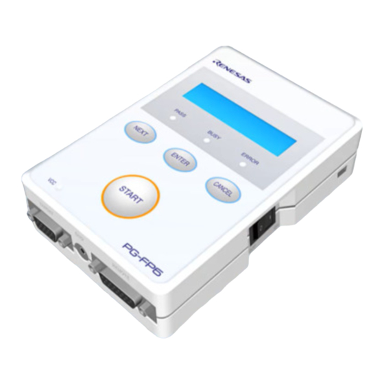
PG-FP6 V1.08 2. FP6 Main Unit: Names and Functions of Parts 2.FP6 Main Unit: Names and Functions of Parts This chapter gives the names and functions of the parts on the FP6 main unit. FP6 Control Panel Indicators and buttons are placed on the top of the FP6. -
Page 27: Fp6 Connectors
PG-FP6 V1.08 2. FP6 Main Unit: Names and Functions of Parts FP6 Connectors The power-supply connector, serial port, and USB connector are placed on the host interface side of the FP6. The target connector, GND connector, and remote connector are placed on the target connector side of the FP6. - Page 28 PG-FP6 V1.08 2. FP6 Main Unit: Names and Functions of Parts Security slot Power switch Figure 2.5 Power Switch R20UT5274EJ0100 Rev.1.00 Page 28 of 186 Apr.01.23...
- Page 29 PG-FP6 V1.08 2. FP6 Main Unit: Names and Functions of Parts (1) Power-supply connector Connect the power-supply connector to the power adapter for your region. For details on the power- supply connector specifications, refer to chapter 10, Connectors and Cables.
-
Page 30: Software Installation
PG-FP6 V1.08 3. Software Installation 3.Software Installation This chapter explains how to install software. Obtaining Software Download the PG-FP6 software from the following Web page. https://www.renesas.com/pg-fp6 Note: We recommend the use of the latest version of software to assure the correct operation of the FP6. -
Page 31: Notes On Installation
(11) To change the folder of the installed tools, uninstall all software related to CS+ (integrated development environment from Renesas), the FP6 Terminal, and the USB driver, and install them again. (12) In the environment where CS+, the FP6 Terminal, and the USB driver for the FP6 are installed, the FP6 Terminal and the USB driver for the FP6 are included in the target software of the CS+ integrated uninstaller. -
Page 32: Uninstallation
PG-FP6 software Use [Add or Remove Programs] on the Control Panel to uninstall the FP6 Terminal and the USB driver. The names are [PG-FP6] and [Renesas USB Driver x86 for PG-FP6] (or [Renesas USB Driver x64 for PG-FP6]), respectively. R20UT5274EJ0100 Rev.1.00 Page 32 of 186 Apr.01.23... -
Page 33: Usage Of The Fp6 Terminal
PG-FP6 V1.08 4. Usage of the FP6 Terminal 4.Usage of the FP6 Terminal Main Window The main window of the FP6 Terminal that has been started up is shown below. Figure 4.1 Main Window Table 4.1 Main Window Name Description... - Page 34 PG-FP6 V1.08 4. Usage of the FP6 Terminal (B) Toolbar The frequently used menu items can be executed by clicking on the buttons. For details on the toolbar, see section 4.5, Toolbar. (C) Console window This window shows the execution result and log of commands.
-
Page 35: Creating A New Setting
PG-FP6 V1.08 4. Usage of the FP6 Terminal Creating a New Setting 4.2.1 [Create New Setting] dialog box Selecting [File]-[New Setting File…] from the menu bar opens the [Create New Setting] dialog box, as shown below. Figure 4.2 [Create New Setting] Dialog Box (A) Target device Select the family, group, and type name of the target device. -
Page 36: Setup] Dialog Box
PG-FP6 V1.08 4. Usage of the FP6 Terminal [Setup] Dialog Box Figure 4.3 [Setup] Dialog Box (A) [Download to FP6] button Clicking on this button applies the changes made in the [Setup] dialog box to the setting file, and closes the [Setup] dialog box. -
Page 37: Program Files] Tabbed Page
PG-FP6 V1.08 4. Usage of the FP6 Terminal 4.3.1 [Program Files] tabbed page The [Program Files] tabbed page allows you to select the files to be written to the target device. Figure 4.4 [Program Files] Tabbed Page (A) Endian Select the endian according to the data of the program file. This item is not displayed when the target device does not support switching of the endian. - Page 38 PG-FP6 V1.08 4. Usage of the FP6 Terminal (C) [Add] button This opens a dialog box for opening a file to be added to the list of files. If a binary file or user key file is selected in this dialog box, the [Offset Address] dialog box opens to allow specifying the programming start address.
-
Page 39: Operation Settings] Tabbed Page
PG-FP6 V1.08 4. Usage of the FP6 Terminal 4.3.2 [Operation Settings] tabbed page The [Operation Settings] tabbed page allows you to change settings related to the operation of flash memory. Remark: Some items may not be displayed or the values of some items may not be changeable depending on the selected target device or program file. - Page 40 PG-FP6 V1.08 4. Usage of the FP6 Terminal Program Flash Options • This command makes settings of flash options such as lock bits, OTP, flash access window, option bytes, and security. These settings correspond to those configured on the [Block Settings] and [Flash Options] tabbed pages.
- Page 41 PG-FP6 V1.08 4. Usage of the FP6 Terminal Verify in the device Data are re-sent to the MCU in response to the verify command and the MCU side handles comparison. Depending on the specifications of the verify command, the range for comparison may extend beyond the programmed data, and this may lead to an error in verification if “Fill with 0xFF”...
-
Page 42: Block Settings] Tabbed Page
PG-FP6 V1.08 4. Usage of the FP6 Terminal 4.3.3 [Block Settings] tabbed page The [Block Settings] tabbed page allows you to set blocks to be handled. Caution: If the selected file is HCUHEX or RPI, the [Block Settings] tabbed page is not displayed. The blocks to be handled are processed as all blocks (chip mode) with the lock bits and OTP is processed according to the content of the RPI file if this is the file type. - Page 43 PG-FP6 V1.08 4. Usage of the FP6 Terminal 4.3.3.2 Case of other device types Figure 4.8 [Block Settings] Tabbed Page (Case of Other Device Types) (A) Information on area blocks Specify the target blocks for erasure, programming, and verification. Cautions: 1.
-
Page 44: [Flash Options] Tabbed Page
PG-FP6 V1.08 4. Usage of the FP6 Terminal 4.3.4 [Flash Options] tabbed page The [Flash Options] tabbed page allows you to specify flash options for the target device. Remark: Only those items the target device supports are shown. For the meanings and details of the settings of the individual items, refer to the user's manual of the target device in use. - Page 45 PG-FP6 V1.08 4. Usage of the FP6 Terminal “Prohibit inside the range”: Programming or erasing of blocks within the range from the start block to the end block is prohibited. “Disable rewriting” • “No”: Making changes within the access window is not disabled.
- Page 46 PG-FP6 V1.08 4. Usage of the FP6 Terminal (G) Reset Vector Enter the reset vector value of the target device in hexadecimal notation. (H) Security Code Set the ID code or the access password. “Set Option” • “Do Nothing”: An ID code or access password is not set.
- Page 47 “Set”: The setting of boundaries is enabled. “Renesas Partition Data File” • Use the Renesas Partition Data File to make the settings of “Secure [KB]” and “NSC [KB]” on boundaries. “Secure [KB]” • Enter the size of the secure area in KB units.
-
Page 48: Connect Settings] Tabbed Page
PG-FP6 V1.08 4. Usage of the FP6 Terminal 4.3.5 [Connect Settings] tabbed page The [Connect Settings] tabbed page allows you to fill the information necessary for connecting the MCU. Remark: The items displayed on this page vary with the type of the target device. - Page 49 PG-FP6 V1.08 4. Usage of the FP6 Terminal Tool Details • Click on this button to open the [Tool Details] dialog box, which enables setting of the states of the mode pins at the time of connection and of the reset pin at the time of disconnection.
- Page 50 Points for Caution stated in the Release Note, which can be obtained from the Renesas Tools homepage (https://www.renesas.com/pg-fp6). In addition, specify whether a clock in the target system or that on the FP6 side is the source of the clock signal for supply to the target device.
- Page 51 FP6 repeats it up to three times if ID code authentication fails. When an RA-family, Renesas Synergy-family, or RE-family device is connected to the FP6, input values to be specified for registers of the target device in order of bits 127 to 0 in byte units. Since the input specification may also differ with the tool, confirm the input specification of the tool you will be using.
-
Page 52: Menu Bar
PG-FP6 V1.08 4. Usage of the FP6 Terminal Menu Bar 4.4.1 [File] menu 4.4.1.1 [New Project…] This menu item is used to select a new target device and create a new setting file. 4.4.1.2 [Open Project…] This menu item is used to open a setting file which has been created and download it to the FP6. - Page 53 PG-FP6 V1.08 4. Usage of the FP6 Terminal (B) [Upload Program File] When a program file is to be uploaded, specify the file format (S-Record or Intel Hex) and select the check box. Although the text box initially shows a file name, the name can be changed.
- Page 54 PG-FP6 V1.08 4. Usage of the FP6 Terminal 4.4.1.5 [Recently used setting files] This menu item is used to display the setting files that have most recently been created (up to eight filenames). Figure 4.15 [Recently used setting files] Dialog Box 4.4.1.6 [Exit]...
-
Page 55: Programmer] Menu
PG-FP6 V1.08 4. Usage of the FP6 Terminal 4.4.2 [Programmer] menu 4.4.2.1 [Connection to FP6] This menu item is used to select the port and baud rate for communications between the FP6 Terminal and the FP6 main unit. [Connection to FP6] dialog box •... - Page 56 PG-FP6 V1.08 4. Usage of the FP6 Terminal 4.4.2.3 [Logging] This menu item is used to save the communication log for the results of command execution displayed on the console window. Selecting this menu item opens the [Save File] dialog box, in which you can specify the location where the file will be saved and the file name.
- Page 57 PG-FP6 V1.08 4. Usage of the FP6 Terminal 4.4.2.5 [Self Test] This menu item is used for self-testing of the FP6. [Self Test] dialog box • After self-testing of the FP6 hardware has completed, the following dialog box will appear to show the result of self-testing of the FP6 hardware.
- Page 58 PG-FP6 V1.08 4. Usage of the FP6 Terminal 4.4.2.6 [Programmer Setting] This menu item is used to make security settings, such as disabling uploading or modification of FP6 settings, and change the operation mode of the FP6 main unit. [FP6 Options] dialog box •...
- Page 59 PG-FP6 V1.08 4. Usage of the FP6 Terminal <Bank Mode> In this mode, the active programming area is switched by using bank signals instead of a standalone menu. For bank mode, refer to chapter 6, Usage of the Remote Connector.
- Page 60 PG-FP6 V1.08 4. Usage of the FP6 Terminal If a password is already set in the FP6, the [Login to FP6 Security Manager] dialog box will appear. In this dialog box, enter the password and log in to the [FP6 Security Manager] menu.
- Page 61 PG-FP6 V1.08 4. Usage of the FP6 Terminal Remark: If boot protection is set, the operation of the target device is restricted until the protection is released by the correct authentication pattern after the FP6 has been started. Caution: Changing the settings in the FP6, removing data, and uploading data from the FP6 are enabled even before release from boot protection by using the authentication pattern.
-
Page 62: Target Device] Menu
PG-FP6 V1.08 4. Usage of the FP6 Terminal 4.4.3 [Target Device] menu This menu is used to perform operations for the target device, such as erasure or programming. When the selected target device does not support a given function, the corresponding menu item will be hidden. This menu is invalid when the FP6 main unit has not been connected. - Page 63 PG-FP6 V1.08 4. Usage of the FP6 Terminal (A) List of areas Specify the area to be read. (B) Information on an area Displays information on an area selected in the list of areas. (C) [Skip blank areas] If this checkbox is selected, blank areas of the target device are to be skipped in the reading of data from memory.
- Page 64 PG-FP6 V1.08 4. Usage of the FP6 Terminal (B) Use Unique ID authentication When this checkbox is selected, the unique ID authentication feature is used during transition to the RMA state. 4.4.3.11 Checksum This command acquires the checksum of data of flash memory in the target device.
- Page 65 PG-FP6 V1.08 4. Usage of the FP6 Terminal (C) [Save these to new setting file] checkbox Select this checkbox if you wish to save the flash-option data that have been acquired as a new setting file. R20UT5274EJ0100 Rev.1.00 Page 65 of 186...
-
Page 66: Toolbar
PG-FP6 V1.08 4. Usage of the FP6 Terminal Toolbar The menu items frequently used on the FP6 Terminal are displayed as buttons on the toolbar. Similar to the target menus on the menu bar, some buttons may be hidden depending on the selected operation or type of the target device. -
Page 67: Example Of Operation Using The Fp6 Terminal
PG-FP6 V1.08 4. Usage of the FP6 Terminal Example of Operation Using the FP6 Terminal This chapter explains a series of basic FP6 operations using the FP6 Terminal, taking a case where the RL78/G14 is used as the target device as an example. -
Page 68: Starting Up The Fp6 Terminal
PG-FP6 V1.08 4. Usage of the FP6 Terminal 4.6.4 Starting up the FP6 Terminal 1. Click on the [Start] menu and select [PG-FP6] to start the FP6 Terminal. 2. When the FP6 Terminal is started correctly and connected to the FP6, the main window is opened. -
Page 69: Setting Up A Programming Environment
PG-FP6 V1.08 4. Usage of the FP6 Terminal 4.6.5 Setting up a programming environment 1. When the main window is opened, select [New Project…]. Figure 4.27 [New Project] Menu 2. Create a new setting file. Select the family, group, and type name of the target device, and enter a setting name as shown in Figure 4.28, and click on the [OK] button. - Page 70 PG-FP6 V1.08 4. Usage of the FP6 Terminal 3. The [Setup] dialog box will appear. Designate a program file on the [Program Files] tabbed page. Click on the [Browse…] button to select a file. Figure 4.29 Selecting a Program File 4.
-
Page 71: Executing The [Start] Command
PG-FP6 V1.08 4. Usage of the FP6 Terminal 4.6.6 Executing the [Start] command Execute the [Start] command from the [Target Device] menu. Figure 4.31 [Start] Command When the [Start] command is executed, the [Erase] and [Program] commands are executed in that order for the R5F104PJ. -
Page 72: System Shutdown
Note: If an error has occurred in the above steps, refer to chapter 12, Troubleshooting, and appendix A, Messages. Also refer to 4.4.2.5, [Self Test], and perform self-testing. If this does not resolve the problem, see the FAQ (https://www.renesas.com/pg-fp6/faq-en) or access https://www.renesas.com/contact for inquiry. -
Page 73: Usage In Standalone Mode
PG-FP6 V1.08 5. Usage in Standalone Mode 5.Usage in Standalone Mode The FP6 has a standalone mode in which the FP6 by itself can execute the [Erase], [Program], and [Start] commands without a host PC. This mode is useful for using the FP6 on the production line during mass production and for upgrading in the field. - Page 74 PG-FP6 V1.08 5. Usage in Standalone Mode Main menu Submenu ENTER button Commands > Commands Projects > Projects CANCEL button Utility > Utility ENTER button NEXT button Set LCD Contr. > F/W Version Command RS232C Baud rate execution NEXT button Figure 5.1...
-
Page 75: Standalone Operation Menu
PG-FP6 V1.08 5. Usage in Standalone Mode Standalone Operation Menu In standalone mode, the programming environment of the target device can be checked and then programs can be written by using the commands explained in this section. 5.2.1 [Commands] menu The [Commands] menu provides various commands required for programming the target device. -
Page 76: Project] Menu
PG-FP6 V1.08 5. Usage in Standalone Mode 5.2.2 [Project] menu The [Project] menu is used to check information about switching the active programming area and checking the setting file name, program file name, and CRC value. Table 5.4 [Project] Menu... -
Page 77: Usage Of The Remote Connector
PG-FP6 V1.08 6. Usage of the Remote Connector 6.Usage of the Remote Connector This chapter describes the usage of the remote connector. The FP6 can be remotely controlled by connecting the remote connector and external control device. Remote control can be used to operate and check programming and the display of PASS, BUSY or ERROR from the external control device. -
Page 78: Usage Of Communications Commands
PG-FP6 V1.08 7. Usage of Communications Commands 7.Usage of Communications Commands This chapter describes how to use communications commands from a host PC to operate the FP6. Starting the Communications Software In order to use communications commands for operation, communications with the FP6 must be established with communications software. -
Page 79: Command Lists
PG-FP6 V1.08 7. Usage of Communications Commands When communications software starts correctly, the main window will open. If communications are established, then a “>” will be displayed when the Enter key on the host PC is pressed. This completes the preparation for using communications commands. - Page 80 PG-FP6 V1.08 7. Usage of Communications Commands Table 7.2 List of FP6 Device Commands Command Name Description Executes the blank check. Executes the Configuration clear. Executes the processes from “transition to flash memory programming mode” to “signature verification”. dcon Executes the termination of the flash memory programming mode.
-
Page 81: Description Of Commands
PG-FP6 V1.08 7. Usage of Communications Commands Description of Commands Each of the commands is described using the following format. Command name Presents an overview of the command. Input format Presents the input format for the command Note Description of the function Describes the function of the command. -
Page 82: Description Of Fp6 Control Commands
PG-FP6 V1.08 7. Usage of Communications Commands Description of FP6 Control Commands 7.4.1 autocon command This command is used to select whether to automatically or manually connect or disconnect the target device in the following processes, or to refer to the current setting. -
Page 83: Brt Command
PG-FP6 V1.08 7. Usage of Communications Commands 7.4.2 brt command Confirms and changes the data transfer rate for serial communications with the host PC. Input format 'brt' ('get' | '9600' | '19200' | '38400' | '57600' | '115200') Description of the function This command can be used with its options to change the data transfer rate for serial communications with the host PC. -
Page 84: Clear Command
PG-FP6 V1.08 7. Usage of Communications Commands 7.4.3 clear command Turns the PASS and ERROR LEDs off. Input format 'clear' Description of the function Turns the PASS and ERROR LEDs on the FP6 main unit off and clears the PASS and ERROR signals of the remote connector. -
Page 85: Conf Command
PG-FP6 V1.08 7. Usage of Communications Commands 7.4.4 conf command Displays a list of the information stored in the FP6. Input format 'conf' Description of the function Displays information on data downloaded to the FP6 and the settings of the FP6. - Page 86 PG-FP6 V1.08 7. Usage of Communications Commands R7F701708 92AC1CBE PR5 test-3.es6 A43294EC ESF {invalid} {invalid} {invalid} {invalid} {invalid} {invalid} {invalid} {invalid} AutoCon is on Sound is on EP mode: Standard speed mode is middle. Security state is: Inactive Boot protection: disabled...
-
Page 87: Downprm Command
PG-FP6 V1.08 7. Usage of Communications Commands 7.4.5 downprm command Downloads the parameter file. Input format 'downprm' <Parameter file data> Description of the function Downloads the parameter file to the FP6 main unit. Before executing the downset command, be sure to execute the downprm command to download the parameter file. -
Page 88: Fcks Command
PG-FP6 V1.08 7. Usage of Communications Commands 7.4.7 fcks command Gets a checksum value of the program file that was downloaded to the active programing area of the FP6. Input format 'fcks' (<type> (<start1> <end1> (<start2> <end2> (<start3> <end3> (<start4> <end4> (<start5> <end5>)))))) Description of the function Gets a checksum value of the program file in the active programming area. -
Page 89: Files Command
PG-FP6 V1.08 7. Usage of Communications Commands 7.4.8 files command Displays the information concerning the program file, DLM key, and user key that were downloaded to the FP6. Input format 'files' (‘key’) ('check') Description of the function If no options are used, the information (file name, creation date, size, and checksum) concerning the program file downloaded to the FP6 is displayed. -
Page 90: Fp_Mode Command
PG-FP6 V1.08 7. Usage of Communications Commands 7.4.9 fp_mode command Switches the operating mode of the FP6 main unit. Input format 'fp_mode' (‘Standard’ | ‘Bank’ | ‘Simple’ | ‘Terminal’) Description of the function Switches the standalone mode of the FP6 main unit. Changing from the standalone mode to the simple mode or return from the simple mode to the standalone mode leads to automatic restarting of the FP6 main unit. -
Page 91: Hex Command
PG-FP6 V1.08 7. Usage of Communications Commands 7.4.10 hex command Uploads the program file to the host PC in Intel HEX format. Input format 'hex' (<start1><length1>(<start2><length2>(<start3><length3>(<start4><length4>)))) Description of the function If a program file has been downloaded to an active programming area, executing this command will upload the program file in Intel HEX format. -
Page 92: Hlp Command
PG-FP6 V1.08 7. Usage of Communications Commands 7.4.11 hlp command Lists available commands with brief descriptions. Input format 'hlp' Description of the function Lists available commands with brief descriptions. Example of usage Example of Communication Software Terminal Display >hlp -------------- Control commands --------------... -
Page 93: Lod Command
PG-FP6 V1.08 7. Usage of Communications Commands 7.4.12 lod command Downloads the program file, DLM key, and user key to the active programming area of the FP6. Input format 'lod' ('add') ('key' <type> (<address>)) (fname="<filename>") ('ftime="<date and time>") Description of the function Downloads the program file, DLM key, and user key to an active programming area. - Page 94 PG-FP6 V1.08 7. Usage of Communications Commands Example of usage Command Status Status LED Message Display Screen Output Display after execution of the BUSY *** BUSY *** Preparing storage ..PASS command (before downloading) Now loading... Display during downloading BUSY *** BUSY ***...
-
Page 95: Prm Command
PG-FP6 V1.08 7. Usage of Communications Commands 7.4.13 prm command Displays the information concerning the parameter file and setting file that were downloaded to the FP6. Input format 'prm' Description of the function Displays the information concerning the parameter file and setting file (parameter file name, parameter file checksum, setting file checksum, and setting file name) that were downloaded to all the programming areas of the FP6. -
Page 96: Progarea Command
PG-FP6 V1.08 7. Usage of Communications Commands 7.4.14 progarea command Confirms and changes information on the active programming areas and deletes data from the programming areas. Input format 'progarea' ('clear' '0' | '1' | '2' | '3' | '4' | '5' | '6' | '7') | ('0' | '1' | '2' | '3' | '4' | '5' | '6' | '7') Description of the function The active programming area can be changed by designating a numerical option. -
Page 97: Res Command
PG-FP6 V1.08 7. Usage of Communications Commands 7.4.15 res command Resets FP6. Input format 'res' Description of the function Resets and restarts the FP6 main unit. Example of usage Example of Communication Software Terminal Display >res Starting FP6... Firmware Version Vx.xx.xx Board H/W Vx Serial No.:xxxxxxxxxx... -
Page 98: Selftest Command
PG-FP6 V1.08 7. Usage of Communications Commands 7.4.16 selftest command Executes a diagnostic test. Input format 'selftest' Description of the function Executes a self-test to diagnose hardware faults. Example of usage Example of Communication Software Terminal Display >selftest ***** CAUTION ***** Remove any plugs from Target- and Remote-Connector before starting. -
Page 99: Serno Command
PG-FP6 V1.08 7. Usage of Communications Commands 7.4.17 serno command Sets the unique code for embedding in the program file. Input format 'serno' <start address> <pattern> Description of the function Sets the unique code for embedding in the program file. This command becomes available when the unique code function is enabled by the FP6 Security Manager setting. -
Page 100: Set_Auth_Id Command
PG-FP6 V1.08 7. Usage of Communications Commands 7.4.18 set_auth_id command Changes the authentication ID code to a desired value. Input format 'set_auth_id' <type> <id> Description of the function When the authentication ID code is changed from the value in the settings file, this command is used to specify the type of authentication ID code for which the value is to be set as the desired ID code. -
Page 101: Sound Command
PG-FP6 V1.08 7. Usage of Communications Commands 7.4.19 sound command Sets the buzzer. Input format 'sound' ('off' | 'on' | 'all') Description of the function Sets the buzzer. “Enabled” or “disabled” is optionally designated. If no option is designated, the current setting is displayed. -
Page 102: Speed_Mode Command
PG-FP6 V1.08 7. Usage of Communications Commands 7.4.20 speed_mode command Adjusts the waiting time and timeout time for use in communications with the target device. Input format 'wait_mode' ('middle' | 'low' | 'high' ) Description of the function With devices of the V850 (except for V850E2) and 78K (except for 78K0S) family as the targets, this command adjusts the waiting time and timeout time in communications with the target device according to the following options. -
Page 103: Srec Command
PG-FP6 V1.08 7. Usage of Communications Commands 7.4.21 srec command Uploads the program file in Motorola S format. Input format 'srec' (<start1><length1>(<start2><length2>(<start3><length3>(<start4><length4>)))) Description of the function If a program file has been downloaded to an active programming area, executing this command will upload the program file in Motorola S format. -
Page 104: Trc Command
PG-FP6 V1.08 7. Usage of Communications Commands 7.4.22 trc command Displays the communication information between the FP6 and target device. Input format 'trc' Description of the function Displays the communication information between the FP6 and target device. Up to 4096 lines can be stored. -
Page 105: Upprm Command
PG-FP6 V1.08 7. Usage of Communications Commands 7.4.23 upprm command Uploads the parameter file. Input format 'upprm' Description of the function If the parameter file has been downloaded to an active programming area, executing this command will upload the parameter file. -
Page 106: Ver Command
PG-FP6 V1.08 7. Usage of Communications Commands 7.4.25 ver command Displays the FP6 version. Input format 'ver' Description of the function Displays the FP6 version (firmware version, board hardware version, and serial number). Example of usage Example of Communication Software Terminal Display >ver... -
Page 107: Description Of Fp6 Device Commands
PG-FP6 V1.08 7. Usage of Communications Commands Description of FP6 Device Commands 7.5.1 bln command Executes the blank check. Input format 'bln' Description of the function Executes blank checking for the flash memory of the target device. The area specified in operation mode is checked. -
Page 108: Clr Command
PG-FP6 V1.08 7. Usage of Communications Commands 7.5.2 clr command Executes “Configuration clear”. Input format 'clr' Description of the function Executes “Configuration clear”. Remark: For details of the “Configuration clear”, refer to the user’s manual of the MCU. Example of usage Example of Communication Software Terminal Display >clr... -
Page 109: Dlm Command
PG-FP6 V1.08 7. Usage of Communications Commands 7.5.5 dlm command Refers to the DLM state and causes a transition of the state. Input format 'dlm' (<type>) ('unique' <authentication code>) Description of the function Refers to the DLM state of the target device and causes a transition of the state. -
Page 110: Ep Command
PG-FP6 V1.08 7. Usage of Communications Commands 7.5.6 ep command Executes the [Start] command. Input format 'ep' or 'epv' Description of the function Executes the [Start] command. Example of usage Command Status Status LED Message Display FP6 Response Message Display while executing the... -
Page 111: Ers Command
PG-FP6 V1.08 7. Usage of Communications Commands 7.5.7 ers command Executes the Erase command. Input format 'ers' Description of the function Erases the target flash memory. The range specified in operation mode is to be erased. If this command is executed with the “Erase Chip” specified, initialization of flash options is also executed. -
Page 112: Gdi Command
PG-FP6 V1.08 7. Usage of Communications Commands 7.5.9 gdi command Gets the information of blank check and flash option. Input format 'gdi' Description of the function Obtains the information of blank check and flash options. Example of usage Example of Communication Software Terminal Display >gdi... -
Page 113: Ged Command
PG-FP6 V1.08 7. Usage of Communications Commands 7.5.10 ged command Gets the information of endian. Input format 'ged' Description of the function Gets the information of endian. Example of usage Example of Communication Software Terminal Display >ged Get Endianness Little Endian PASS Get Endianness operation finished. -
Page 114: Glb Command
PG-FP6 V1.08 7. Usage of Communications Commands 7.5.12 glb command Gets the lock bit. Input format 'glb' Description of the function Gets the lock bit. Example of usage Example of Communication Software Terminal Display >glb LockBits : CF1: FFFFFFFFFFFFFFFFFFFFFFFFFFFFFFFFFFFFFFFFFFFFFFFFFFFFFFFFFFFFFFFFFFFFFFFFFFFFFFFFFFFFFFFFFFFFFFFFFFFFFFFFFFFFFFFFFFFFFFFFFFFFFFFFF CF2: FFFFFFFFFFFFFFFFFFFFFFFFFFFFFFFFFFFFFFFFFFFFFFFFFFFFFFFFFFFFFFFF... -
Page 115: Gof Command
PG-FP6 V1.08 7. Usage of Communications Commands 7.5.14 gof command Gets the information of OFS. Input format 'gof' Description of the function Gets the information of OFS. Remark: For details of OFS, refer to the user’s manual of the MCU. -
Page 116: Got Command
PG-FP6 V1.08 7. Usage of Communications Commands 7.5.16 got command Gets the information of OTP. Input format 'got' Description of the function Gets the information of OTP. Remark: For details of OTP, refer to the user’s manual of the MCU. -
Page 117: Gtm Command
PG-FP6 V1.08 7. Usage of Communications Commands 7.5.18 gtm command Gets the information of Trusted Memory. Input format 'gtm' Description of the function Gets the information of Trusted Memory. Remark: For details of Trusted Memory, refer to the user’s manual of the MCU. -
Page 118: Idc Command
PG-FP6 V1.08 7. Usage of Communications Commands 7.5.19 idc command Executes the ID code setting. Input format 'idc' (<ID Code>) Description of the function Sets the ID code and code flash and data flash passwords (the passwords are only applicable in the case of RH850/P1x-C devices) for use in on-chip debugging of the MCU. -
Page 119: Opb Command
PG-FP6 V1.08 7. Usage of Communications Commands 7.5.20 opb command Sets the option bytes. Input format 'opb' Description of the function Sets the option bytes. Example of usage Example of Communication Software Terminal Display >opb Set Option Bytes PASS Option Bytes operation finished. -
Page 120: Pfo Command
PG-FP6 V1.08 7. Usage of Communications Commands 7.5.22 pfo command Sets the flash options collectively. Input format 'pfo' Description of the function Sets the flash options collectively. Example of usage Example of Communication Software Terminal Display >pfo Set Flash Option PASS Program Flash Option operation finished. -
Page 121: Prg Command
PG-FP6 V1.08 7. Usage of Communications Commands 7.5.23 prg command Executes programming. Input format 'prg' Description of the function Executes programming. When filling with 0xFF is disabled, programming is performed to the locations where program file data exist. In this case, data is programmed with the minimum alignment unit of the MCU. -
Page 122: Read Command
PG-FP6 V1.08 7. Usage of Communications Commands 7.5.24 read command Reads data of the flash memory in the target device. Input format 'read' ('skipblank') ('hex' | 'srec') ('all' | <start_address> <end_address>) Description of the function Reads data of the flash memory in the target device and outputs the data in the specified format. -
Page 123: Rsc Command
PG-FP6 V1.08 7. Usage of Communications Commands 7.5.25 rsc command Executes the Security Release command. Input format 'rsc' Description of the function Executes the Security Release command. Remark: For details of the Security Release command, refer to the user’s manual of the MCU. -
Page 124: Sed Command
PG-FP6 V1.08 7. Usage of Communications Commands 7.5.27 sed command Executes the endian setting. Input format 'sed' Description of the function Executes the endian setting. Example of usage Example of Communication Software Terminal Display >sed Set Endianness PASS Set Endianness operation finished. -
Page 125: Sig Command
PG-FP6 V1.08 7. Usage of Communications Commands 7.5.29 sig command Executes the [Read Signature] command. Input format 'sig' Description of the function Executes the [Read Signature] command. Example of usage Example of Communication Software Terminal Display >sig Device name: D70FXXXX Device data: 10 DF 40 Device Version: 2.00... -
Page 126: Spd Command
PG-FP6 V1.08 7. Usage of Communications Commands 7.5.31 spd command Disables the serial programming. Input format 'spd' Description of the function Disables the serial programming for the MCU. Example of usage Example of Communication Software Terminal Display >spd Set Serial Programming Disable PASS Set SerProgDis operation finished. -
Page 127: Sum Command
PG-FP6 V1.08 7. Usage of Communications Commands 7.5.33 sum command Executes the Checksum command. Input format 'sum' Description of the function Executes the Checksum command and gets checksum values in the MCU. Example of usage Example of Communication Software Terminal Display >sum... -
Page 128: Encryption Utility Program
PG-FP6 V1.08 8. Encryption Utility Program 8.Encryption Utility Program rpe.exe, which is bundled with this product, can be used to encrypt or decrypt program files. Remark: rpe.exe is stored in the same location as that for FP6.exe in the folder where the FP6 Terminal has been installed. -
Page 129: Renesas Flash Programmer Utility Program
PG-FP6 V1.08 9. Renesas Flash Programmer Utility Program 9.Renesas Flash Programmer Utility Program The Renesas Flash Programmer utility program, rfp-util.exe, which had been bundled with this product from FP6 Terminal V1.07, has been discontinued. Use the Security Key Management Tool as the successor software. -
Page 130: 10.Connectors And Cables
PG-FP6 V1.08 10. Connectors and Cables 10.Connectors and Cables 10.1 Power-Supply Connector The power-supply connector is laid out on the host interface side of the FP6. Power-supply connector Figure 10.1 Power-Supply Connector Figure 10.2 Pin Assignments of the Power-Supply Connector Note: Do not connect a power adapter other than the one for the PG-FP6 to the power-supply connecter. -
Page 131: Serial Connector
PG-FP6 V1.08 10. Connectors and Cables 10.2 Serial Connector The serial connector (9-pin D-sub male connector) is laid out on the host interface side of the FP6. Serial port Figure 10.3 9-Pin D-Sub Serial Connector Figure 10.4 Pin Assignments of the Serial Connector Table 10.1 Pin Configuration of the 9-Pin D-Sub Serial Connector... -
Page 132: Serial Cable Connected To The 9-Pin D-Sub Serial Connector
PG-FP6 V1.08 10. Connectors and Cables 10.2.1 Serial cable connected to the 9-pin D-sub serial connector A serial cross cable is additionally required. The connectors on both sides are 9-pin D-sub female connectors. The following shows the connection. Figure 10.5 Connection of the Serial Cable 10.3... -
Page 133: Target Connector
PG-FP6 V1.08 10. Connectors and Cables 10.4 Target Connector The target connector is laid out on the right side of the FP6. Target connector Figure 10.8 Target Connector (Target Connector Side of the FP6) Note: Part number of the target connector (15-pin D-sub female connector): D02-M15SAG-20L9E (manufactured by Japan Aviation Electronics Industry, Limited) Figure 10.9 Pin Assignments of the Target Connector (15-Pin D-Sub Female Connector) -
Page 134: Target Cable (14-Pin Type)
PG-FP6 V1.08 10. Connectors and Cables 10.4.1 Target cable (14-pin type) The target cable (14-pin type) is a standard shielded cable and is approximately 42 centimeters long. The target cable is equipped with a 15-pin D-sub male connector and a 14-pin 2.54-mm pitch multipurpose female connector. -
Page 135: 14-Pin To 16-Pin Conversion Adapter For The E1 Emulator
PG-FP6 V1.08 10. Connectors and Cables Table 10.3 Pin Configuration of the Target Connector (14-Pin Type) Signal Name 15-Pin D-Sub Male Connector 14-Pin 2.54-mm Pitch Multipurpose Female Connector (PG-FP6) SCK/IO4 CLK/IO5 FLMD0/IO0 SI/RxD SO/TxD1/IO3 FLMD1 TxD2/HS ¯¯¯¯¯¯ RESET Not used * ... -
Page 136: 20-Pin Conversion Adapter For The Pg-Fp6
PG-FP6 V1.08 10. Connectors and Cables 10.4.3 20-pin conversion adapter for the PG-FP6 When the CoreSight 20-pin connector is used on the target system, use the 20-pin conversion adapter for the PG-FP6. When the 10-pin connector is used on the target system, use the 20-pin to 10-pin conversion cable to match it. -
Page 137: Gnd Connector
PG-FP6 V1.08 10. Connectors and Cables 10.5 GND Connector The banana-jack GND connector is laid out on the target connector side of the FP6. GND connector Note: Part number of the GND connector (banana jack): PB4 (manufactured by HIRSCHMANN) Figure 10.13 GND Connector (Target Connector Side of the FP6) R20UT5274EJ0100 Rev.1.00... -
Page 138: Gnd Cable
PG-FP6 V1.08 10. Connectors and Cables 10.5.1 GND cable The GND cable is approximately one meter long. The cable is equipped with a banana jack and a spade terminal. Note: The FP6 and target system may be damaged if there are differences in potential between the grounds of the FP6 and of the target system. - Page 139 PG-FP6 V1.08 10. Connectors and Cables Table 10.5 Pin Functions of the Remote Interface Input/ Pin Name Function Active Number Output Level Output CONN Indicates that the remote interface is connected. When High level the power of the FP6 is ON, the CONN is always valid.
-
Page 140: 11.Examples Of Connections With The Target Device
11. Examples of Connections with the Target Device 11.Examples of Connections with the Target Device For examples of recommended connections between the PG-FP6 and the target devices, refer to the FP6, Renesas Flash Programmer Additional Document for User’s Manual (Recommended Circuits for Connecting the Flash Programmer). -
Page 141: 12.Troubleshooting
The connection with the target system might be wrong. Action 1: Confirm that the connection with the target system is correct by referring to the PG-FP6, Renesas Flash Programmer Additional Document for User’s Manual (Recommended Circuits for Connecting the Flash Programmer). -
Page 142: When An Error Produces The Message '023 Inv. Sig. Addr
The connection to the target system may be wrong. Action 1: Confirm that the connection with the target system is correct by referring to the PG-FP6, Renesas Flash Programmer Additional Document for User’s Manual (Recommended Circuits for Connecting the Flash Programmer). - Page 143 PG-FP6 V1.08 12. Troubleshooting Cause 2: Settings of the target system and FP6 may not match. Action 2: (1) Baud rate: Check the operating frequency of the target device to see if the baud rate exceeds the allowable communications rate and if the baud rate is appropriate.
-
Page 144: 13.Points For Caution
PG-FP6 V1.08 13. Points for Caution 13.Points for Caution This chapter gives some notes on rewriting the memory in the target device. 13.1 Checking before Connection Applies to: All MCUs • Connection of the target device in the cases listed below may damage the tool in use or the target system due to conflicts between signals. -
Page 145: Wide Voltage Mode
PG-FP6 V1.08 13. Points for Caution 13.5 Wide Voltage Mode Applies to: 78K0R family • If you wish to enable wide voltage mode, select the [Wide Voltage] check box on the [Connect Setting] tabbed page of the [Setup] dialog box. Since the FP6 ignores any wide voltage setting in a HCUHEX file, this is the case regardless of whether you are using an HCUHEX file. -
Page 146: Verification After Protecting The Mcu
PG-FP6 V1.08 13. Points for Caution 13.8 Verification after Protecting the MCU Applies to: RH850, RX64M, RX71M, RX66T, RX72T • Setting the following protection functions of the MCU restricts the verification function. ID code protection Proceeding with verification (“Verify by reading the device”) without issuing a reset after the ID code protection bit has been set (written) will cause a protection error. -
Page 147: 14.Maintenance And Warranty
Failure or damage attributable to modifications, repairs, adjustments, or other acts made to the product by other than Renesas Electronics Corporation. (3) Consumables (e.g., sockets and adapters) are not covered by the aforementioned repair. In the above cases, contact your local distributor. If your product is being leased, consult the leasing company or the owner. -
Page 148: How To Make Request For Repair
PG-FP6 V1.08 14. Maintenance and Warranty (3) Expiration of the repair period When a period of one year has elapsed after production of a given model ceased, repairing products of that model may become impossible. (4) Carriage fees for sending your product to be repaired Carriage fees for sending your product to us for repair are at your own expense. -
Page 149: Appendix A. Messages
PG-FP6 V1.08 Appendix A. Messages Appendix A. Messages This chapter explains the messages. Messages Defined in the FP6 Terminal Message Description E0000001 Operation with a file failed. The file name exceeds the available number of characters or includes characters that are not usable in the OS, or the permission settings for the specified file or folder may not allow the operation. - Page 150 PG-FP6 V1.08 Appendix A. Messages Message Description E0003003 A communications error occurred. Communications with the FP6 were stopped. Check for problems with the cable connected to the FP6. If you are using the FP6 in an environment such as Windows 7, automatically reconnection of the FP6 main unit may not be possible when it is restarted.
-
Page 151: Error Messages Produced By The Fp6 Main Unit
PG-FP6 V1.08 Appendix A. Messages Error Messages Produced by the FP6 Main Unit The following describes the error messages produced by the FP6 main unit. The first rows of the Message column are messages displayed in the message display of the main unit. The second and subsequent rows of the Message column are messages displayed in the FP6 Terminal. - Page 152 PG-FP6 V1.08 Appendix A. Messages Message Possible Workaround Inv. Sig. ID An attempt was made to connect a target device which differs from that when the settings file was created. Create a new settings file or use the correct settings file with the target Invalid signature device.
- Page 153 PG-FP6 V1.08 Appendix A. Messages Message Possible Workaround Write timeout A timeout occurred when a problem in communications between the target device and the FP6 arose for some reason. Check the connection to the target device and confirm that the Communication target device has not been reset.
- Page 154 PG-FP6 V1.08 Appendix A. Messages Message Possible Workaround SCF Comm err This error code and message are displayed when programming of flash options in the target device was attempted but failed. Communication Possible causes of the error (failure to program) include: failure or timeout.
- Page 155 FP6 main unit might be damaged. Run a self-test. If this does not resolve the problem, contact a Renesas Electronics sales representative or distributor. FP6 int Vcc fail The FP6 main unit might be damaged. Contact a Renesas Electronics sales representative or distributor. Power failure.
- Page 156 PG-FP6 V1.08 Appendix A. Messages Message Possible Workaround GID Comm err An error occurred during execution of the ‘gid’ command. This might be due to a problem with communications between the FP6 and target device. Refer to section 12.2, Problems Communication during Operation.
- Page 157 Nos. 094, 108, 587, 590, 591, or 592 Communication might have occurred. failure or timeout. FP6 Power err The FP6 main unit might be damaged. Contact a Renesas Electronics sales representative or distributor. Power Failure detected. LCD Timeout The FP6 main unit might be damaged.
- Page 158 PG-FP6 V1.08 Appendix A. Messages Message Possible Workaround DAP err This error occurs when the CPU clocks are stopped. Confirm that the clocks are correctly being supplied to the target device. An error occurred during setting of If there are no problems with the clocks, the device may be in the snooze mode or the CPU clock.
-
Page 159: Error Messages Produced By The Fp6 Main Unit That Are Only Displayed In The Terminal
PG-FP6 V1.08 Appendix A. Messages Error Messages Produced by the FP6 Main Unit that are Only Displayed in the Terminal The following describes the error messages produced by the FP6 main unit that are only displayed in the USB- or serial-connected terminal. -
Page 160: List Of Security And Safety Functions Of The Target Device That May Affect The Operation Of The Programmer
PG-FP6 V1.08 Appendix A. Messages List of Security and Safety Functions of the Target Device that May Affect the Operation of the Programmer The following lists the security and safety functions of the target device that may affect the error messages with descriptions that include security functions. -
Page 161: Appendix B. Supplementary Information
PG-FP6 V1.08 Appendix B. Supplementary Information Appendix B. Supplementary Information This chapter covers supplementary information referred to by the user’s manual of the FP6. 32-Bit CRC Method The generator polynomial used for this table is x^32+x^26+x^23+x^22+x^16+x^12+x^11+x^10+x^8+x^7+x^5+x^4+x^2+x^1+x^0 according to Autodin/Ethernet/ADCCP protocol standards... -
Page 162: Division Method
PG-FP6 V1.08 Appendix B. Supplementary Information crc_accum= 0xFFFFFFFF; /* Init Pattern */ for (i= 0, rd_ptr= 16; i < length; i++) /* Check flash read buffer and fill if needed */ if (rd_ptr == 16) Memory_Read (address, 16, data); rd_ptr= 0;... -
Page 163: 16-Bit Crc Method
PG-FP6 V1.08 Appendix B. Supplementary Information 16-Bit CRC Method /* The generator polynomial used for this table is: */ /* x^16+x^12+x^5+x^0 according to CCITT-16 standard. */ /* Binary: 0x1021 */ const uint16_t CRC16_Tab [256]= { 0x0000,0x1021,0x2042,0x3063,0x4084,0x50A5,0x60C6,0x70E7, 0x8108,0x9129,0xA14A,0xB16B,0xC18C,0xD1AD,0xE1CE,0xF1EF, 0x1231,0x0210,0x3273,0x2252,0x52B5,0x4294,0x72F7,0x62D6, 0x9339,0x8318,0xB37B,0xA35A,0xD3BD,0xC39C,0xF3FF,0xE3DE, 0x2462,0x3443,0x0420,0x1401,0x64E6,0x74C7,0x44A4,0x5485,... - Page 164 PG-FP6 V1.08 Appendix B. Supplementary Information /* Check flash read buffer and fill if needed */ if (rd_ptr == 0) Memory_Read (address, 4, data); rd_ptr= 4; address+= 4; byte= (crc_accum >> 8) ^ data [--rd_ptr]; crc_accum= (crc_accum << 8) ^ CRC16_Tab [byte];...
-
Page 165: Appendix C. Equivalent Circuits Of The Target Interface
PG-FP6 V1.08 Appendix C. Equivalent Circuits of the Target Interface Appendix C. Equivalent Circuits of the Target Interface This chapter shows equivalent circuits of the target interface. Figure C.1 Equivalent Circuits of the Target Interface R20UT5274EJ0100 Rev.1.00 Page 165 of 186... -
Page 166: Appendix D. Electrical Specifications Of The Remote Interface
PG-FP6 V1.08 Appendix D. Electrical Specifications of the Remote Interface Appendix D. Electrical Specifications of the Remote Interface This chapter gives the electrical specifications of the remote interface. Absolute Maximum Ratings (T =0 to 40°C) Pin name Symbol Parameter or Conditions... -
Page 167: Ac Characteristics (T =0 To 40°C, C=0Pf (Unloaded Condition))
PG-FP6 V1.08 Appendix D. Electrical Specifications of the Remote Interface AC Characteristics (T =0 to 40°C, C=0pF (Unloaded Condition)) D.3.1 Standard mode Pin name Symbol Parameter or Conditions MIN. TYP. MAX. Unit CONN Rise time(I =8mA) BUSY Fall time (I =8mA) ... - Page 168 PG-FP6 V1.08 Appendix D. Electrical Specifications of the Remote Interface Pin name Symbol Parameter or Conditions MIN. TYP. MAX. Unit Time from the fall of the VRF, START, PINBU or ENTER signal until the rise of the BUSY signal Time from the fall of the BUSY signal ...
-
Page 169: Bank Mode
PG-FP6 V1.08 Appendix D. Electrical Specifications of the Remote Interface D.3.2 Bank mode Pin name Symbol Parameter or Conditions MIN. TYP. MAX. Unit CONN Rise time (I =8mA) BUSY Fall time (I =8mA) PASS ERROR BANK0 Low-level width of input signal ... - Page 170 PG-FP6 V1.08 Appendix D. Electrical Specifications of the Remote Interface Pin name Symbol Parameter or Conditions MIN. TYP. MAX. Unit Time from the fall of the BANK signal PBAIN until the VRF or START signal can be input Time from the fall of the VRF, START ...
-
Page 171: Simple Mode
PG-FP6 V1.08 Appendix D. Electrical Specifications of the Remote Interface D.3.3 Simple mode Pin name Symbol Parameter or Conditions MIN. TYP. MAX. Unit CONN Rise time (IO=8mA) BUSY Fall time (IO=8mA) PASS ERROR CANCEL Low-level width of input signal ... - Page 172 PG-FP6 V1.08 Appendix D. Electrical Specifications of the Remote Interface Pin name Symbol Parameter or Conditions MIN. TYP. MAX. Unit Time from the fall of the NEXT signal PBAIN until the VRF or START signal can be input Time from the fall of the VRF, START or ...
- Page 173 PG-FP6 V1.08 Appendix D. Electrical Specifications of the Remote Interface PINBU BUSY NEXT PPENE PBAIN ENTER START PASS ERROR PCLPE PBUIN CLEAR R20UT5274EJ0100 Rev.1.00 Page 173 of 186 Apr.01.23...
-
Page 174: Appendix E. Electrical Specifications Of The Target Interface
PG-FP6 V1.08 Appendix E. Electrical Specifications of the Target Interface Appendix E. Electrical Specifications of the Target Interface This chapter gives the electrical specifications of the target interface. Absolute Maximum Ratings (T =0 to 40°C) Pin name Symbol Parameter or Conditions... -
Page 175: Dc Characteristics (T A =0 To 40°C)
PG-FP6 V1.08 Appendix E. Electrical Specifications of the Target Interface DC Characteristics (T =0 to 40°C) Pin name Symbol Parameter or Conditions MIN. TYP. MAX. Unit Output voltage, high Output voltage, high (I = 100 mA) – 5% + 5% Input current, high ... -
Page 176: Appendix F. Setting The Multiplier
PG-FP6 V1.08 Appendix F. Setting the Multiplier Appendix F. Setting the Multiplier This chapter introduces requirements for the supported MCU groups. For the range of values that can be selected for "Input Frequency" and "Multiplier", refer to the user's manual for the MCU. -
Page 177: Rx62G, Rx62T
PG-FP6 V1.08 Appendix F. Setting the Multiplier RX62G, RX62T Input Frequency Multiplier CPU 1.0, 2.0, 4.0, 8.0 8 MHz ≤ fx ≤ 12.5 MHz Peripheral 1.0, 2.0, 4.0, 8.0 Ensure that [Input Frequency] × [Multiplier (CPU)] = 8 MHz to 100 MHz (for ICLK) and [Input Frequency] ×... -
Page 178: 78K0/Dx2, 78K0/Fx2, 78K0/Kx2, 78K0/Kx2-C, 78K0/Lx2, 78K0/Lx3, 78K0/Lx3-M, Upd78F0730, Upd78F8019, Upd78F8020, Upd78F8024/Upd78F8025, Upd78F8032, Upd78F8077
PG-FP6 V1.08 Appendix F. Setting the Multiplier RX63T: Other than the R5F563TB, R5F563TC, and R5F563TE Input Frequency Multiplier CPU 1.0, 2.0, 4.0, 8.0, 16.0 4 MHz ≤ fx ≤ 16 MHz Peripheral 1.0, 2.0, 4.0, 8.0 Ensure that [Input Frequency] × [Multiplier (CPU)] = 4 MHz to 100 MHz (for ICLK) and [Input Frequency] ×... -
Page 179: V850Es/Kx1, V850Es/Kx1+, V850Es/Kx2
PG-FP6 V1.08 Appendix F. Setting the Multiplier F.16 V850ES/Kx1, V850ES/Kx1+, V850ES/Kx2 Input Frequency Multiplier Speed 2 MHz ≤ fx ≤ 5 MHz CPU 4.0 For 2-wire UART communications, do not select 115,200 or 500,000 bps. 5 MHz < fx ≤ 10 MHz CPU 1.0... -
Page 180: V850Es/Fx3-L
PG-FP6 V1.08 Appendix F. Setting the Multiplier F.21 V850ES/Fx3-L Input Frequency Multiplier Speed 4 MHz ≤ fx ≤ 5 MHz CPU 4.0 5 MHz < fx ≤ 10 MHz CPU 2.0 For 2-wire UART communications, do not select 500,000 bps. -
Page 181: V850E2/Fx4-G
PG-FP6 V1.08 Appendix F. Setting the Multiplier F.25 V850E2/Fx4-G UPD70F3592 Input Frequency Multiplier Speed 4 MHz CPU 20.0 4 MHz < fx ≤ 5 MHz CPU 16.0 5 MHz < fx ≤ 8 MHz CPU 10.0 For 1-wire UART communications, do not select 2,000,000 bps. -
Page 182: Sh7253
PG-FP6 V1.08 Appendix F. Setting the Multiplier SH7214: R5F72145G, R5F72146G, R5F72147G, R5F72145H, R5F72146H, R5F72147H SH7216: R5F72165G, R5F72166G, R5F72167G, R5F72165H, R5F72166H, R5F72167H Input Frequency Multiplier CPU 2.0, 4.0, 8.0, 16.0 10 MHz ≤ fx ≤ 12.5 MHz Peripheral 2.0, 4.0 Ensure that [Input Frequency] × [Multiplier (CPU)] = 20 MHz to 100 MHz (for ICLK) and [Input Frequency] ×... -
Page 183: Sh72A0
PG-FP6 V1.08 Appendix F. Setting the Multiplier F.30 SH72A0 Input Frequency Multiplier CPU 8.0 8 MHz, 10 MHz Peripheral 4.0 F.31 SH72A2 Input Frequency Multiplier CPU 10.0 8 MHz, 10 MHz Peripheral 5.0 R20UT5274EJ0100 Rev.1.00 Page 183 of 186 Apr.01.23... - Page 184 Revision History PG-FP6 V1.08 Flash Memory Programmer User’s Manual Rev. Date Description Page Summary 1.00 Apr.01.23 First Edition issued ...
- Page 185 Colophon PG-FP6 V1.08 User’s Manual Publication Date: Rev.1.00 Apr.01.23 Published by: Renesas Electronics Corporation...
- Page 186 Back cover PG-FP6 V1.08 R20UT5274EJ0100...
Need help?
Do you have a question about the PG-FP6 V1.08 and is the answer not in the manual?
Questions and answers