Table of Contents
Advertisement
Quick Links
Description
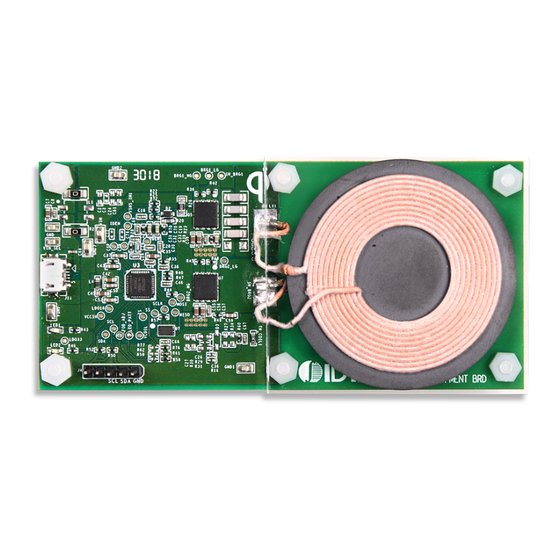
The P9235A-RB-EVK Mass-Market Evaluation Board demon-
strates the features of the P9235A-RB 5W Wireless Power
Transmitter (TX). It is intended to evaluate the functionality and
performance of the P9235A-RB when combined with a power
receiver in a wireless charging system. The P9235A-RB-EVK
offers the flexibility to select parameters, such as the over-current
limit threshold, LED pattern, and external temperature sensing
function. The printed circuit board (PCB) has four layers.
The P9235A-RB Evaluation Board is designed to function with the
P9225-R Receiver Evaluation Board, which is ordered separately
(see
www.idt.com/p9225-r-evk
the user's WPC-1.2.4 compliant receiver.
The high-efficiency, turnkey reference design is supported by
comprehensive online digital resources to significantly expedite the
design-in effort and enable rapid prototyping. The total active area
is optimized to 21mm x 21mm.
Kit Contents
P9235A-RB-EVK Mass-Market Evaluation Board
P9235A-RB Transmitter Board Connected to P9225-R-EVK
© 2019 Integrated Device Technology, Inc.
P9235A-RB-EVK Evaluation Board User Manual
for details). It can also be used with
Features
P9235A-RB Evaluation Board provides support for WPC-1.2.4
Power capability: 5W for 5V input
Adjustable over-current protection (OCP) threshold
Adjustable temperature shutdown
Two programmable LED status indicators
Supports 5V input voltage
Secured authentication (16-bit private key and 16-bit random
number)
Fully assembled with test points and coil fixture
P9235A-RB-EVK Mass-Market Evaluation Board
Transmitter Coil
1
P9225-RB-EVK Receiver Board
VOUT and GND Test Points
February 21, 2019
Advertisement
Table of Contents

Subscribe to Our Youtube Channel
Related Manuals for Renesas P9235A-RB-EVK


Summary of Contents for Renesas P9235A-RB-EVK
- Page 1 Adjustable over-current protection (OCP) threshold performance of the P9235A-RB when combined with a power Adjustable temperature shutdown receiver in a wireless charging system. The P9235A-RB-EVK offers the flexibility to select parameters, such as the over-current Two programmable LED status indicators limit threshold, LED pattern, and external temperature sensing ...
-
Page 2: Table Of Contents
Restrictions in Use IDT’s P9235A-RB-EVK Mass-Market Evaluation Board and the P92xx 5-15W Wireless Power Pro software are designed for evaluation purposes only. The P9235A- RB-EVK Mass-Market Evaluation Board and software must not be used for module production or production test setups. - Page 3 P9235A-RB-EVK Evaluation Board User Manual List of Figures Figure 1. Connecting the Dongle ..................................4 Figure 2. P9235A-RB V1P1 Evaluation Board Features ............................5 Figure 3. P9235A-RB Evaluation Board Details ..............................6 Figure 4. R61 and R62 Schematic Location ...............................8 Figure 5. R61 and R62 PCB Location ................................8 Figure 6.
-
Page 4: Setup
P92xx 5-15W Wireless Power Pro GUI User Manual, which is available upon request from IDT Step 2: Use the dongle to connect the P9235A-RB-EVK with the user’s computer as shown in Figure 1. Figure 1. -
Page 5: Kit Hardware Connections
P9235A-RB-EVK Evaluation Board User Manual Kit Hardware Connections Follow these procedures to set up the kit as shown on page 1. 1. Set up the P9235A-RB Evaluation Board by plugging the 5V adapter or the user’s power supply into J11 (Micro-USB connector). Refer to Figure 2. -
Page 6: Figure 3. P9235A-Rb Evaluation Board Details
P9235A-RB-EVK Evaluation Board User Manual Figure 3. P9235A-RB Evaluation Board Details © 2019 Integrated Device Technology, Inc. February 21, 2019... -
Page 7: Led Pattern
The LEDs are connected to the LED1 and LED2 pins as shown on the P9235A-RB-EVK schematics (see section 3). The LED patterns can be selected by setting the voltage on the LED_PAT pin via the resistor divider R61 and R62; see Table 1 for the options. On the P9235A-RB-EVK, the LED_PAT pin is pulled up to 3.3V through R61. -
Page 8: Figure 4. R61 And R62 Schematic Location
P9235A-RB-EVK Evaluation Board User Manual Figure 4. R61 and R62 Schematic Location Figure 5. R61 and R62 PCB Location © 2019 Integrated Device Technology, Inc. February 21, 2019... -
Page 9: Ocp And Fod Tuning
FOD function. When ILIM/FOD_ADJ voltage is greater than 2.4V, FOD is enabled, and vice versa. The OCP threshold is always set to 2400mA. On the P9235A-RB-EVK, the ILIM/FOD_ADJ pin is pulled up to 3.3V through R58. R59 is unpopulated, so the FOD function is enabled. -
Page 10: External Temperature Sensing - Ts
P9235A-RB-EVK Evaluation Board User Manual External Temperature Sensing – TS The P9235A-RB includes an optional temperature sense input pin, TS, used to monitor a remote temperature, such as for a coil or a battery charger. The TS pin voltage can be calculated by Equation 1. -
Page 11: Programming Interface
(OTP) and flash memory. The OTP file is burned into the P9235A-RB memory. For the flash file, the bootloader (part of the flash file) is burned into the P9235A-RB memory; the other part of the flash file is programmed into the flash chip (U7) on the P9235A-RB-EVK. The P92xx 5-15W Wireless Power Pro GUI can be used for programming the OTP or the flash file. -
Page 12: P9235A-Rb Evaluation Board V1P1 Schematic
P9235A-RB-EVK Evaluation Board User Manual 3. P9235A-RB Evaluation Board V1P1 Schematic © 2019 Integrated Device Technology, Inc. February 21, 2019... -
Page 13: Bill Of Materials (Bom)
P9235A-RB-EVK Evaluation Board User Manual 4. Bill of Materials (BOM) Table 3. P9235A-RB-EVK BOM Item Reference Value Description Part Number PCB Footprint Quantity C7, C31, C32, C35, 10µF CAP CER 10UF 10V X5R 0603 GRM188R61A106KE69D 0603 C42, C45, C55, C56 C8, C30, C33, C34, 0.1µF... - Page 14 P9235A-RB-EVK Evaluation Board User Manual Item Reference Value Description Part Number PCB Footprint Quantity R39, R49 RES SMD 0 OHM JUMPER 1/16W 0402 RC0402JR-070RP 0402 R41, R43 1kΩ RES SMD 1K OHM 5% 1/16W 0402 RC0402JR-071KL 0402 680Ω RES SMD 680 OHM 5% 1/16W 0402...
-
Page 15: Board Layout
P9235A-RB-EVK Evaluation Board User Manual 5. Board Layout Figure 10. Silkscreen – Top of Board Figure 11. Copper – Top Layer © 2019 Integrated Device Technology, Inc. February 21, 2019... -
Page 16: Figure 12. Copper L1 Layer
P9235A-RB-EVK Evaluation Board User Manual Figure 12. Copper L1 Layer Figure 13. Copper L2 Layer © 2019 Integrated Device Technology, Inc. February 21, 2019... -
Page 17: Figure 14. Copper Bottom
P9235A-RB-EVK Evaluation Board User Manual Figure 14. Copper Bottom © 2019 Integrated Device Technology, Inc. February 21, 2019... -
Page 18: Ordering Information
P9235A-RB-EVK Evaluation Board User Manual 6. Ordering Information Orderable Part Number Description P9235A-RB-EVK P9235A-RB-EVK Evaluation Board 7. Revision History Revision Date Description of Change February 21, 2019 Initial release. Corporate Headquarters Sales Tech Support 6024 Silver Creek Valley Road 1-800-345-7015 or 408-284-8200 www.IDT.com/go/support... - Page 19 Koto-ku, Tokyo 135-0061, Japan www.renesas.com/contact/ www.renesas.com Trademarks Renesas and the Renesas logo are trademarks of Renesas Electronics Corporation. All trademarks and registered trademarks are the property of their respective owners.
Need help?
Do you have a question about the P9235A-RB-EVK and is the answer not in the manual?
Questions and answers