Table of Contents
Advertisement
Quick Links
WARNING:
If the information in these instructions is not followed exactly, a fire or explosion may result
causing property damage, personal injury or loss of life.
DO NOT PLACE ARTICLES ON OR AGAINST THIS APPLIANCE.
DO NOT USE OR STORE FLAMMABLE MATERIALS NEAR THIS APPLIANCE.
DO NOT SPRAY AEROSOLS IN THE VICINITY OF THIS APPLIANCE WHILE IT IS IN OPERATION.
DO NOT MODIFY THIS APPLIANCE.
-
Do not store or use gasoline or other flammable vapors and liquids in the vicinity of this or any other
appliance.
WHAT TO DO IF YOU SMELL GAS
• Do not try to light any appliance.
• Do not touch any electrical switch; do not use any phone in your building.
• Immediately call gas supplier from a neighbor's phone. Follow the gas supplier's instructions.
• If you cannot reach your gas supplier, call the fire department.
-
Installation and service must be performed by a qualified installer, service agency or the gas supplier.
This appliance may be installed in
an aftermarket permanently
located, manufactured home (USA
only) or mobile home, where not
prohibited by local codes.
This appliance is only for use
with the type(s) of gas indicated
on the rating plate. A conversion
kit is supplied with the appliance.
Installation Manual
Installer:
After installation give this manual to the home-
owner and explain operation of this heater.
Copyright 2020, T.I.
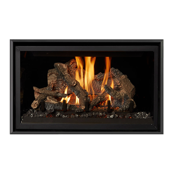
564 GSR2 35K
CF Deluxe
Fireplace
Installation Manual
$10.00
100-01554
Dragon Wholesaling Pty. Ltd.
Unit 4, 16 Lexington Drive
Bella Vista NSW
5/3/21
Listed By
AS/NZS 5263.1.3
GMK10022
IAPMO-R&T OCEANA
Australia 2153
Advertisement
Table of Contents

Related Manuals for Lopi 564 GSR2 35K CF Deluxe


Summary of Contents for Lopi 564 GSR2 35K CF Deluxe
- Page 1 Listed By 564 GSR2 35K CF Deluxe AS/NZS 5263.1.3 GMK10022 Fireplace IAPMO-R&T OCEANA Installation Manual WARNING: If the information in these instructions is not followed exactly, a fire or explosion may result causing property damage, personal injury or loss of life. ...
-
Page 2: Overview
Introduction Overview This manual details the installation requirements for the 564 GSR2 35K CF fireplace. For operating and maintenance instructions, refer to the 564 GSR2 35K CF Owner's Manual. © Travis Industries 5/3/2021 - 1554 564 GSR2 35K CF (AUST) -
Page 3: Table Of Contents
Table of Contents Overview ............2 Top Vent Configuration with Horizontal Termination..........26 Installation Options ........6 Top Vent Configuration with Vertical Heating Specifications ........6 Termination..........27 Dimensions ............ 6 Termination Requirements ......28 Packing List ........... 7 Hearth Requirements ........29 Additional Items Required ...... - Page 4 Safety Precautions Safety Warnings Failure to follow all of the requirements may result in property damage, bodily injury, or even death. Young children should be carefully supervised when they are in the same room as the appliance. Toddlers, young children and others may be susceptible to accidental contact burns.
- Page 5 Safety Precautions Safety Warnings (continued) Because this heater can be controlled by a thermostat there is a possibility of the heater turning on and igniting any items placed on or near the appliance. Light the heater using the built-in igniter. Do not use matches or any other external device to light your heater. ...
-
Page 6: Installation Options
Features and Specifications Installation Options Residential or Mobile Home Internal or External Chase Straight or Corner Placement Horizontal or Vertical Vent Flush or Recessed Face Bedroom Approved Raised or Floor Placement Heating Specifications Natural Gas Propane Approximate Heating Capacity (in square meters)*... -
Page 7: Packing List
Finalizing the Installation (for qualified installers only) Packing List Propane Conversion Kit (Front #58 Orifice, Rear #C55 Orifice, Pilot Orifice 0.14 LP). 2 Piece Firestop (sku# 250-05641) Remote Embers, Rockwool, Ember-Glass Additional Items Required Log Set ... -
Page 8: Pipe Shield Installation
Finalizing the Installation (for qualified installers only) Pipe Shield Installation The pipe shield must be installed as shown below. NOTE: The header and pipe shields may be installed after the fireplace is in place and vent attached (this allows for the fireplace to fit into the framing underneath the header and for the vent to be installed more easily). -
Page 9: Standoff And Drywall Support Preparation
Finalizing the Installation (for qualified installers only) Standoff and Drywall Support Preparation The two standoffs and three drywall supports are shipped in the flat position. Make sure to bend (and secure) the standoffs and drywall supports as shown below. Bend both standoff s as shown below. -
Page 10: Fireplace Placement Requirements
Finalizing the Installation (for qualified installers only) Fireplace Placement Requirements Fireplace must be installed on a level surface capable of supporting the fireplace and vent Fireplace must be placed directly on wood or non-combustible surface (not on linoleum or carpet) ... -
Page 11: Minimum Framing Dimensions
Finalizing the Installation (for qualified installers only) Minimum Framing Dimensions Minimum Max. Header Depth Enclosure 3” (77mm) Height 58-1/4" (1480mm) 70-1/4" (1784mm) 37-1/4" (947mm) 38-3/4" (985mm) 19-3/8" (493mm) Flush Install 18-7/8" (480mm) Extended (T ile Over) Install © Travis Industries 3/17/2022 - 1554 564 GSR2 35K CF (AUST) -
Page 12: Minimum Vent "Bump Out" Application - Top Vent
Finalizing the Installation (for qualified installers only) Minimum Vent “Bump Out” application – Top Vent Min. 11” (280mm)* Min. 6” (153mm)* 8” (204mm) Certain configurations Vent may require vertical vent Centerline sections (see “Vent Requirements” for details. SIDE OF FIREPLACE Base of Fireplace * See “Vent Termination... -
Page 13: Nailing Brackets
Finalizing the Installation (for qualified installers only) Nailing Brackets The fireplace has nailing brackets on both sides. Once in place, secure the fireplace to the framing. NOTE: Make sure the fireplace is square and plumb when securing the fireplace. SPECIAL NOTE WHEN USING “SUBMERGED FACING” OPTION Most installations use the “Standard Facing”... -
Page 14: Corner Installations
Finalizing the Installation (for qualified installers only) Corner Installations A typical 45° installation uses the framing dimensions shown in the illustration below (NOTE: all clearances still apply). Minimum 1/2" (13mm) Clearance 14-1/4" (362mm) 47-5/8" Min. (1210mm) NOTE ON PIPE SHIELD: When venting horizontally in a corner application, one side of the pipe shield may be... -
Page 15: Outdoor Fireplace Installations
Finalizing the Installation (for qualified installers only) Outdoor Fireplace Installations Travis Industries Inc. gas-fired fireplaces are suitable for installation into outdoor areas protected from direct water impingement. In addition to maintaining listed mantel and combustibles clearances, a rain protection overhang factor of 1/2 shall be constructed to the front and to each side of installed appliances (see the illustration to the right). -
Page 16: Gas Line Requirements
Finalizing the Installation (for qualified installers only) Gas Line Requirements MASSACHUSETTS INSTALLATIONS - WARNING: THIS PRODUCT MUST BE INSTALLED BY A LICENSED PLUMBER OR GAS FITTER WHEN INSTALLED WITHIN THE COMMONWEALTH OF MASSACHUSETTS. OTHER MASSACHUSETTS CODE REQUIREMENTS: Flexible connector must not be longer than 36 inches. ... -
Page 17: Gas Line Location
Finalizing the Installation (for qualified installers only) Gas Line Location NOTE FOR RIGID PIPE: When using rigid pipe, you may wish to disconnect the shutoff valve from the fireplace and route the pipe through the fireplace wall. First, disconnect the gas line from the shutoff valve (see step 1 below). -
Page 18: (Required)
Finalizing the Installation (for qualified installers only) Electrical Connection (required) The electrical line to the grounded receptacle inside the fireplace must be installed by a qualified installer and must meet all local codes. Make sure the household breaker is shut off prior to working on any electrical lines. ... -
Page 19: Accessing The Area Under The Burner
Finalizing the Installation (for qualified installers only) Accessing the Area Under the Burner The lower panel may be removed to access components. This is required when relocating the electrical or gas inlet location or installing the LP regulator. (a) Loosen the four nuts. (b) Lift the panel up, rotate it forward and remove. -
Page 20: Vent Requirements
Finalizing the Installation (for qualified installers only) Vent Requirements The gas appliance and vent system must be vented directly to the outside of the building, and never be attached to a chimney serving a separate solid fuel or gas-burning appliance. Each direct vent gas appliance must use it's own separate vent system. -
Page 21: Approved Vent
Finalizing the Installation (for qualified installers only) Approved Vent Horizontal Terminations: use 8" (203mm) diameter Dura-Vent Model Direct-Vent Pro*. Vertical Terminations with elbows: use 8" (203mm) diameter Dura-Vent Model Direct-Vent Pro*. Vertical Terminations with no elbows: Use 6-5/8" (168mm) diameter Dura-Vent Direct-Vent Pro*. Attach the 8"... -
Page 22: Approved Vent Configurations
Finalizing the Installation (for qualified installers only) Approved Vent Configurations Restrictor Position Intake and exhaust restrictors are built into the appliance to adjust the flow rate of intake air and exhaust gases. Depending upon the vent configuration, you may be required to adjust the restrictor positions. -
Page 23: Intake Restrictor Adjustment
Finalizing the Installation (for qualified installers only) Intake Restrictor Adjustment The intake restrictor is located on the back wall of the firebox. To adjust the restrictor, follow the steps below: Position # 1 (open) 1/4" Socket Loosen the two screws holding the intake restrictor in place.. -
Page 24: Diffuser Plate Adjustment
Finalizing the Installation (for qualified installers only) Diffuser Plate Adjustment Certain vent configurations require the diffuser plate to be adjusted (refer to the approved vent configuration charts for details). Position # 1 is stock (bent). Position # 2 is flattened. See the directions below to change the diffuser to position #2. -
Page 25: Minimum Vent Configuration
Finalizing the Installation (for qualified installers only) Minimum Vent Configuration Use 5x8” Diameter Coaxial Vent The termination must fall within the shaded area shown in the chart. Use the indicated restrictor and diffuser positions. One 45° elbow may be used on the horizontal run. ... -
Page 26: Top Vent Configuration With Horizontal Termination
Finalizing the Installation (for qualified installers only) Top Vent Configuration with Horizontal Termination The termination must fall within the shaded area shown in the chart. Use the indicated restrictor and diffuser positions. Up to four elbows (45° or 90°) may be used. -
Page 27: Top Vent Configuration With Vertical Termination
Finalizing the Installation (for qualified installers only) Top Vent Configuration with Vertical Termination The termination must fall within the shaded area shown in the chart. Use the indicated restrictor and diffuser positions. Up to four elbows (45° or 90°) may be used. -
Page 28: Termination Requirements
Finalizing the Installation (for qualified installers only) Termination Requirements Venting terminals shall not be recessed into a wall or siding. Minimum 9" (229mm) clearance from any door or window Minimum 12" (305mm) above any grade, veranda, porch, deck or balcony Minimum 1"... -
Page 29: Hearth Requirements
Finalizing the Installation (for qualified installers only) Hearth Requirements © Travis Industries 5/3/2021 - 1554 564 GSR2 35K CF (AUST) -
Page 30: Optional Tile Stop Removal
Finalizing the Installation (for qualified installers only) Optional Tile Stop Removal This fireplace includes an optional tile stop above the glass frame. It is typically removed if the front of the fireplace is left exposed. If using tile or other non-combustible facing over the front of the fireplace, the tile stop is left in place to help support the facing. -
Page 31: Facing Requirements
Finalizing the Installation (for qualified installers only) Facing Requirements The front of fireplace may be left uncovered (see “a” below). NOTE: A custom trim will be required to fill the gap between the wall sheeting and fireplace if finishing in this manner. -
Page 32: Mantel Requirements
Finalizing the Installation (for qualified installers only) Mantel Requirements Combustible Mantels Use the table below to determine the maximum mantel depth allowed. The mantel depth (measured from the face of the fireplace) must fall in the shaded portion of the table. ... -
Page 33: Steps For Finalizing The Installation
Finalizing the Installation (for qualified installers only) Steps for Finalizing the Installation Remove the glass (see page 35). NOTE: If using propane (LP) convert the appliance prior to installing the logs. We recommend you purge the gas line at this time (with the glass removed). This allows gas to be detected once it enters the firebox, ensuring gas does not build up. -
Page 34: Air Shutter Adjustment
Finalizing the Installation (for qualified installers only) 10. Check the air shutter following the directions below. Air Shutter Adjustment Let the heater burn for fifteen minutes (make sure the logs and glass are in place). The flames should be yellow with no sooting. Adjust the air shutter, if necessary, to achieve the correct looking flame. Air Shutter Adjustment 11. -
Page 35: Barrier Removal
Finalizing the Installation (for qualified installers only) Barrier Removal A barrier designed to reduce the risk of burns from the hot viewing glass is provided with this appliance and shall be installed for the protection of children and other at-risk individuals. If the barrier becomes damaged, the barrier shall be replaced with the manufacturer’s barrier for this appliance. -
Page 36: Glass Frame Removal And Installation
Finalizing the Installation (for qualified installers only) Glass Frame Removal and Installation Warning: The appliance must be completely cool before removing the glass. Warning: Do not strike or slam the glass. Note: Remove the barrier before removing the glass (see previous page). Replace barrier after replacing the glass. -
Page 37: Glass Frame Removal And Installation (Continued)
Finalizing the Installation (for qualified installers only) Glass Frame Removal and Installation (continued) The latch can come loose from glass frame anchor. This occurs when it is turned 1/4 turn when it is disengaged. Follow the directions below to re-install the latch if it becomes loose. ©... -
Page 38: Ember Bed Glass And Ember Material Installation
Finalizing the Installation (for qualified installers only) Ember bed Glass and Ember Material Installation Ember bed Glass Installation Make sure the ember skirt is in place. The skirt hooks over the front of the ember platform and slopes outward toward the glass. The skirt helps keep the glass and ember material from falling off the platform when the glass is removed. -
Page 39: Ember Material Installation
Finalizing the Installation (for qualified installers only) Ember Material Installation Once the ember glass installation is complete, place a generous amount of ember material on the firebox floor on either side of the firebox. Completely cover any visible metal on the firebox floor. NOTE: Make sure no ember material is placed directly on the burner. -
Page 40: Log Set Installation
Finalizing the Installation (for qualified installers only) Log Set Installation Installation Warnings NOTE: If using propane (LP), convert the appliance before installing the log set. If using firebacks, install them prior to installing the log set. The logs are fragile, especially after being exposed to heat. ... - Page 41 Finalizing the Installation (for qualified installers only) Installation Rear Log The rear log has two pockets that insert over two tabs on the back burner (see photos below). Place the log in place and push it back. The log straddles the burner and does not cover any burner holes. ©...
- Page 42 Finalizing the Installation (for qualified installers only) Left Log The left log has two flat surfaces on the bottom. Place the log so the flat surfaces rest against the burner as shown below. Make sure the log does not block any burner holes. Right Log The right log has a channel on the bottom that fits over the ridge on the burner.
- Page 43 Finalizing the Installation (for qualified installers only) Front Left Log The front left log has a channel that fits over the grate. When in place, the knob on the front of the log fits over the grate as well. Front Ember Chunk The front ember chunk has a groove on the bottom that fits over the grate.
- Page 44 Finalizing the Installation (for qualified installers only) Center Twig The center twig is shown below. It has a pin on the bottom side. When in place, the fork on the front straddles the grate and the pin rests on the rear burner (make sure it is not over any burner holes). Center Log The center log has a hole on the back and a fork on the front.
- Page 45 Finalizing the Installation (for qualified installers only) Left Twig The left twig has a hole on the bottom that fits over the locating pin on the front left log. Place the twig as shown below. The front left log has a groove that will point the twig upwards and to the right. Center Left Twig The center left twig is flat on the bottom with one hole.
- Page 46 Finalizing the Installation (for qualified installers only) Right Twig The right twig has a hole and a slot on the bottom that fit over the pins on the right log. When properly positioned, the log will be placed as shown below and to the right. ©...
- Page 47 Finalizing the Installation (for qualified installers only) Ember Installation NOTE: The embers are included with the fireplace. Consult the installation manual for details on installing the embers. If using the Ember-Glo light, the embers are installed with the Ember-Glo light glass. Embers are provided to further enhance the firebox.
-
Page 48: Lp Conversion Instructions
Finalizing the Installation (for qualified installers only) LP Conversion Instructions WARNING This conversion kit shall be installed by a qualified service agency in accordance with the manufacturer’s instructions and all applicable codes and requirements of the authority having jurisdiction. If the information in these instructions is not followed exactly, a fire, explosion or production of carbon monoxide may result causing property damage, personal injury or loss of life. - Page 49 Finalizing the Installation (for qualified installers only) Remove the manifold covers. NOTE: Discard the orifice gaskets and the rear manifold cover. Reinstall the front manifold cover after changing the orifices. 3. Follow the directions below to replace the orifice. Slide the air shutters to provide access to the orifices. Remove and discard the two gaskets on the front burner orifice.
- Page 50 Finalizing the Installation (for qualified installers only) Install the LP pilot orifice following the instructions below. (a) Use a 7/16” open-end wrench to remove the pilot hood. (b) Remove and discard the Natural Gas (NG) orifice. Place the LP orifice in the pilot assembly then replace the pilot hood, tightening the pilot hood until it is snug (do not over-tighten).
-
Page 51: Special Instructions For Fireback Installation
Optional Equipment (for qualified installers only) Special Instructions for Fireback Installation - This fireplace may use existing 564 firebacks. However, the instructions included with the firebacks do not include the following caveats: Firebox Baffle Must Be Removed to Install Firebacks (replace once firebacks in place) Firebox Baffle The baffle has heyholes, allowing... - Page 52 Optional Equipment (for qualified installers only) Rear Air Deflector (behind the rear log) Must be Removed (replace after firebacks in place) 1/4" Nutdriver Remove the rear burner. NOTE: when replacing make sure the burner is properly aligned and the holes on the tabs on the burner insert over the pins on the burner stand.
-
Page 53: Attaching The Power Heat Duct To The 564 35K (Optional)
Optional Equipment (for qualified installers only) Attaching the Power Heat Duct to the 564 35k (Optional) One or two optional power heat ducts (sku 98500769) may be attached to the 564 35k. The ducting is attached to the top of the fireplace (left or right side). See the directions below for removing the power heat duct covers. - Page 54 Optional Equipment (for qualified installers only) Remove the lower duct plate screws and plate to allow air to flow from the lower convection channel (see pictures below). Discard the lower duct plate. © Travis Industries 5/3/2021 - 1554 564 GSR2 35K CF (AUST)
-
Page 55: Installing The Power Heat Duct With The 564 35K
Optional Equipment (for qualified installers only) Installing the Power Heat Duct with the 564 35k The power heat duct must be installed in accordance with the instructions included with the kit and all local codes. See the illustration below for an overview Power Heat Duct Wiring Diagram ©... -
Page 56: Coolsmart Tv - Installation Overview (Optional)
Optional Equipment (for qualified installers only) CoolSmart TV – Installation Overview (Optional) The CoolSmart system is designed to redirect the convective heat of the fireplaces from the front of the unit, just above the glass, to a location higher on the wall. The use of this kit allows for reduced clearances to televisions and a recessed cavity above the fireplace. -
Page 57: Coolsmart Tv - Installation Requirements
Optional Equipment (for qualified installers only) CoolSmart TV - Installation Requirements Min. 1-1/4" (32mm) 3/8" (10mm) Upper Manifold Framing Clearance from Top, Sides 1-1/4" (32mm) and Back to Combustibles Ceiling 1-3/4" (45mm) 3/4" (20mm) Min. 1-1/2" (39mm) Manifold 3-3/4" (96mm) Manifold Support Bracket Lower Manifold Framing Min. -
Page 58: Coolsmart Tv - Framing The Chase
Optional Equipment (for qualified installers only) CoolSmart TV - Framing the Chase When using this kit, disregard the framing dimensions in the manual and follow the framing instructions shown below. 26-1/2" (674mm) Braces for Manifold Support Brackets 3-3/4" Bottom of Upper (96mm) Manifold Framing Max. -
Page 59: Coolsmart Tv - Installation
Optional Equipment (for qualified installers only) CoolSmart TV - Installation Remove the grill from the manifold (2 screws hold it in place). Remove the rear-mounting brackets by loosening 1/4" screws and sliding it out of the keyhole slots. Determine the desired location of the bottom of the convection air outlet. Install a horizontal framing member at the desired height, parallel to the header. - Page 60 Optional Equipment (for qualified installers only) Secure the manifold to the upper framing using screws (not included). Secure to framing Re-attach the two rear mounting brackets (removed in step 6) to the bottom of the convection manifold. Leave the screws loose so the brackets can be positioned to the back of the chase. Secure the brackets to the chase using screws (not included).
- Page 61 Optional Equipment (for qualified installers only) Grab on to the knockout with pliers and bend it back and forth until the remaining tabs break free. Discard the knock out plate. Under each knock out plate, you will find a cover plate held in place with (2) ¼” screws. Use a nut driver or drill with an extension to remove the (2) screws.
- Page 62 Optional Equipment (for qualified installers only) 10 You will need to remove a third cover plate on each side. Remove the 2 screws holding the cover plate in place. Reach in and remove the cover plate. You may discard this plate. 11 Repeat the above steps on the other end of the fireplace ©...
- Page 63 Optional Equipment (for qualified installers only) 12 Insert a starter collar into each of the (2) holes that were uncovered in the previous step and bend the tabs to secure the starter collar to the fireplace.. Seal the joints with silicone caulk or aluminum (U.L.
-
Page 64: Coolsmart Tv - Using Oval Pipe To Get Past An Obstruction
Optional Equipment (for qualified installers only) 15 Cover the face of the fireplace and the outlet of the manifold to ensure no construction debris or sheetrock dust enters the unit. 16 Once all finish work is complete around the outlet of the manifold, install the outlet grill assembly using the two included screws (one at each end). -
Page 65: Wiring Diagram
Optional Equipment (for qualified installers only) Wiring Diagram © Travis Industries 5/3/2021 - 1554 564 GSR2 35K CF (AUST) -
Page 66: Index
Index Index Accessing the Area Under the Burner ..... 19 Installation Overview .......... 7 Additional Items Required ........7 Log Set Installation .......... 40 Approved Vent Configurations ......22 LP Conversion Instructions ......48 Barrier Removal ..........35 Mantel Requirements ........32 CoolSmart TV –...
Need help?
Do you have a question about the 564 GSR2 35K CF Deluxe and is the answer not in the manual?
Questions and answers