Table of Contents
Advertisement
WARNING: FIRE OR EXPLOSION HAZARD
Failure to follow safety warnings exactly could result in serious injury, death, or property damage.
- Do not store or use gasoline or other flammable vapors and liquids in the vicinity of this or any
other appliance.
- WHAT TO DO IF YOU SMELL GAS
• Do not try to light any appliance.
• Do not touch any electrical switch; do not use any phone in your building.
• Leave the building immediately
• Immediately call your gas supplier from a neighbor's phone. Follow the gas supplier's
instructions.
• If you cannot reach your gas supplier, call the fire department.
-
Installation and service must be performed by a qualified installer, service agency or the gas supplier.
A barrier designed to reduce the risk of burns from
the hot viewing glass is provided with this appliance
and shall be installed for the protection of children
and other at-risk individuals.
This appliance may be installed in an aftermarket, permanently located, manufactured home
(USA only) or mobile home, where not prohibited by local codes.
This appliance is only for use with the type of gas indicated on the rating plate. A conversion
kit is supplied with the appliance.
INSTALLER: Leave this manual with the appliance.
CONSUMER: Retain this manual for future reference.
Travis Industries, Inc.
Copyright 2018, T.I.
Northfield MV
Owner's Manual
HOT GLASS WILL CAUSE
BURNS
DO NOT TOUCH GLASS
UNTIL COOLED
NEVER ALLOW CHILDREN
TO TOUCH GLASS
12521 Harbour Reach Dr., Mukilteo, WA 98275
$10.00
Direct Vent Room Heater
Natural Gas or Propane
Residential or Mobile Home
French language manuals at travisindustries.com
Manuels de langue Française à travisindustries.com
4/24/18
Tested and Listed by
Report # 0028GH050S
Omni-Test Laboratories, Inc.
Portland, Oregon
ANSI Z21.88-2016
CSA 2.33-2016
CSA 2.17-17
www.travisproducts.com
100-01461
Advertisement
Table of Contents

Related Manuals for Lopi Northfield MV


Summary of Contents for Lopi Northfield MV
- Page 1 Northfield MV Owner’s Manual WARNING: FIRE OR EXPLOSION HAZARD Failure to follow safety warnings exactly could result in serious injury, death, or property damage. - Do not store or use gasoline or other flammable vapors and liquids in the vicinity of this or any other appliance.
-
Page 2: Introduction
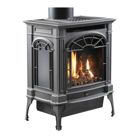
Introduction Introduction We welcome you as a new owner of a Lopi Northfield MV stove. In purchasing a Northfield you have joined the growing ranks of concerned individuals whose selection of an energy system reflects both a concern for the environment and aesthetics. The Northfield is one of the finest home heaters the world over. -
Page 3: Table Of Contents
Optional Blower Installation ........42 Interior Masonry Chimney Conversions (top vent Index ................ 44 configuration only) ..........20 Steps for Finalizing the Installation ...... 21 Air Shutter Adjustment ........21 © Travis Industries 4/20/2018 - 1461 Northfield MV... - Page 4 Do not operate if any portion of the heater was submerged in water or if any corrosion occurs. Immediately call a qualified service technician to inspect the appliance and to replace any part of the control system and any gas control which has been under water. © Travis Industries 4/20/2018 - 1461 Northfield MV...
- Page 5 Travis Gas Fireplaces, Stoves, and Inserts are protected by one or more of the following patents; U.S. 8,469,021, 7,066,170, 6,602,068, 6,443,726, 6,953,037; Canada 2755517 as well as other U.S. and Foreign Patents pending. © Travis Industries 4/20/2018 - 1461 Northfield MV...
-
Page 6: Features
This heater is shipped in natural gas (NG) configuration but may be converted to propane (LP) using the included LP conversion kit. The sticker on top of the gas control valve will verify the correct fuel. © Travis Industries 4/20/2018 - 1461 Northfield MV... - Page 7 The requirements listed below are divided into sections. All requirements must be met simultaneously. The order of installation is not rigid – the qualified installer should follow the procedure best suited for the installation. © Travis Industries 4/20/2018 - 1461 Northfield MV...
-
Page 8: Packing List
Vent (see “Venting Requirements” for details) • Log Set Gas Line Equipment (shutoff valve, pipe, etc.) Installation Overview See "Vent "Clearances" Requirements" See "Gas Line Installation" See "Floor Protection Requirements" © Travis Industries 4/20/2018 - 1461 Northfield MV... -
Page 9: Stove Clearances
When the stove is installed in a mobile home, it must be bolted to the floor and the appliance grounded (use the optional blower with a grounded circuit or other suitable grounding method - current ANSI/NFPA 70 or CSA C22.1). © Travis Industries 4/20/2018 - 1461 Northfield MV... -
Page 10: Heater Placement Requirements
The appliance, when installed, must be electrically grounded in accordance with local codes or, in the absence of local codes, with the National Electrical Code, ANSI/NFPA 70, or the Canadian Electrical Code, CSA C22.1. © Travis Industries 4/20/2018 - 1461 Northfield MV... -
Page 11: Gas Line Installation
The supply regulator (the regulator that attaches directly to the residence inlet or to the propane tank) should supply gas at the suggested input pressure listed above. Contact the local gas supplier if the regulator is at an improper pressure. © Travis Industries 4/20/2018 - 1461 Northfield MV... -
Page 12: Altitude Considerations
Approved Caps Framing for wall thimble Always use the high-wind cap Maintain a minimum 1"(25mm) (the sconce cap is not Horizontal Termination clearance from vent to any combustible. approved for this stove). © Travis Industries 4/20/2018 - 1461 Northfield MV... -
Page 13: Approved Vent
Screws are not required to secure the vent. However, three screws may be used to secure vent sections together if desired. • Horizontal sections require a 1/4" (6.4mm) rise every 12" (305mm) of travel • Horizontal sections require non-combustible support every three feet (e.g.: plumbing tape) © Travis Industries 4/20/2018 - 1461 Northfield MV... -
Page 14: Approved Vent Configurations
When a horizontal elbow (90° or 45°) is to the top of the termination Elbow used, horizontal length is the sum of the on vertical terminations. two lengths (H1 + H2). Vent Vertical Elbow Height © Travis Industries 4/20/2018 - 1461 Northfield MV... -
Page 15: Opening The Diffuser
To open the diffuser, reach into the vent starter section and bend the diffuser back (see photos below). You may need a screwdriver to bend the upper portion of the diffuser 90° (see photos below). Diffuser Closed (stock) Diffuser Open DIFFUSER SIDE VIEW Open Closed (Stock) © Travis Industries 4/20/2018 - 1461 Northfield MV... -
Page 16: Vent Configurations With Vertical Termination
5 feet (1.5m) 5 feet (1.5m) 0 feet 0 feet Horizontal Elbow Horizontal elbows are elbows placed between two horizontal sections of pipe. One 45° or 90° horizontal elbow is allowed for this configuration. © Travis Industries 4/20/2018 - 1461 Northfield MV... -
Page 17: Vent Configurations With Horizontal Termination17
Min. 2' (0.61m) Rise Required 0 feet 0 feet Horizontal Elbow Horizontal elbows are elbows placed between two horizontal sections of pipe. One 45° or 90° horizontal elbow is allowed for this configuration. © Travis Industries 4/20/2018 - 1461 Northfield MV... -
Page 18: Vent Termination Requirements
NOTE: Measure clearances to the nearest edge of the exhaust hood. • Use the vinyl siding standoff when installing on an exterior with vinyl siding. • Vent termination must not be located where it will become plugged by snow or other material © Travis Industries 4/20/2018 - 1461 Northfield MV... -
Page 19: Class A Chimney Conversion Kit (Top Vent Configuration Only)
Travis Industries and it has been determined to be safe following the instructions above. Before installing the appliance using this method, contact the Authority Having Jurisdiction to determine if this installation is acceptable in your area. © Travis Industries 4/20/2018 - 1461 Northfield MV... -
Page 20: Interior Masonry Chimney Conversions (Top Vent Configuration Only)
Before installing the appliance using this method, contact the Authority Having Jurisdiction to determine if this installation is acceptable in your area. © Travis Industries 4/20/2018 - 1461 Northfield MV... -
Page 21: Steps For Finalizing The Installation
The flames should burn off of each burner hole. If the heater does not work correctly, contact your Travis dealer for a remedy. Give this manual to the home owner for future reference and fully explain operation of this heater. © Travis Industries 4/20/2018 - 1461 Northfield MV... -
Page 22: Face And Glass Removal
Swing the glass frame into place - you may have to lift it slightly to allow it to fit over the top of the firebox. c) Attach the upper latches (follow the instructions above in reverse). d) Replace the stove front and top. © Travis Industries 4/20/2018 - 1461 Northfield MV... - Page 23 Top of Firebox Glass Frame Anchor Note how the washer on the latch fits behind the flange on the glass frame anchor. Once fully inserted, turn the latch until it is upright. © Travis Industries 4/20/2018 - 1461 Northfield MV...
-
Page 24: Log Installation
If using propane (LP), convert the appliance before installing the logs (see page 38). Rear Log Placement The rear log has two holes on the bottom. Place the log so the pins on the burner insert into the holes on the log (see photos below). © Travis Industries 4/20/2018 - 1461 Northfield MV... -
Page 25: Left Log Placement
Right Log Placement The right log has two holes on the bottom. Place the log so the two pins on the burner insert into the holes on the log (see photos below). © Travis Industries 4/20/2018 - 1461 Northfield MV... -
Page 26: Left Twig Placement
The right twig has two holes in the bottom that fit over the pin on the back and right log (see photos below). The lower side of the twig rests on the right log. Place the twig as shown below. © Travis Industries 4/20/2018 - 1461 Northfield MV... -
Page 27: Rock Wool Placement
Place a layer of embers along the edges of the burner, on top of rivets, and along the edges to enhance the aesthetics of the firebox. Do not place embers over any burner holes. See the photo to the right. © Travis Industries 4/20/2018 - 1461 Northfield MV... -
Page 28: Before You Begin
This button is used only to start the pilot. When pressed it sends an electrical charge to the pilot assembly. This creates a blue spark directly next to the pilot, igniting the pilot flame. On/Off Switch This switch turns the main burner on and off. © Travis Industries 4/20/2018 - 1461 Northfield MV... -
Page 29: Starting The Pilot
Turn the gas control knob counter-clockwise to "ON". The pilot is now lit and the heater can be turned on and off. DANGER HIGH VOLTAGE: Disconnect power before attempting maintenance or repair. © Travis Industries 4/20/2018 - 1461 Northfield MV... -
Page 30: Starting The Heater For The First Time
Your heater has an adjustable flame to tailor the look and heat output to your specific needs. It is adjusted by turning the middle dial on the gas control valve. Index Mark Flame Height Adjustment Knob Turn counter-clockwise to adjust the flame higher, clockwise to lower. © Travis Industries 4/20/2018 - 1461 Northfield MV... -
Page 31: Adjusting The Blower Speed (Optional)
This is normal during start-up. You may notice the smell is more acute if the appliance was left idle for a long period. Power Outages The heater will work if household current (AC power) is disconnected. © Travis Industries 4/20/2018 - 1461 Northfield MV... -
Page 32: Maintaining Your Stoves Appearance
Remove any debris or vegetation near the vent termination. Contact your dealer if any sooting or deterioration is found near the vent termination. Venting system should be examined by a qualified agency. © Travis Industries 4/20/2018 - 1461 Northfield MV... - Page 33 Short (Under 6") The logs or coals are placed incorrectly See "Log Set Installation" Thin Layer of Soot Improper air shutter adjustment Adjust Air Shutter - contact your dealer Covers the Glass © Travis Industries 4/20/2018 - 1461 Northfield MV...
-
Page 34: Replacement Parts List
SCREEN BARRIER, FRONT 250-03421 PIEZO IGNITER w/ RETAINING NUT 250-00390 THERMO-COUPLE 250-04383 THERMOPILE 250-04380 VALVE, NG w/MAN. SIT 820.644 250-04377 OPTIONAL FAN KIT 99000195 Contact your local Travis Industries Dealer to purchase replacement parts © Travis Industries 4/20/2018 - 1461 Northfield MV... -
Page 35: Wiring Diagram
Thermocouple Thermopile Piezo Igniter On/Off Switch (on fireplace) Brown Copper Co-Axial Wire Orange Spark Electrode White Pilot Hood Optional Wall Switch, Thermostat, or Remote Control Optional Blower Wiring © Travis Industries 4/20/2018 - 1461 Northfield MV... -
Page 36: Safety Label
Safety Label Safety Label The safety (listing) label is on the back of the stove. A copy is shown below. © Travis Industries 4/20/2018 - 1461 Northfield MV... -
Page 37: Conditions & Exclusions
4. Check with your dealer in advance for any costs to you when arranging a warranty call. Mileage or service charges are not covered by this warranty. This charge can vary from store to store. © Travis Industries 4/20/2018 - 1461 Northfield MV... -
Page 38: Lp Conversion Instructions
LP Pilot orifice – (0.14) 250-02763 LP Regulator 250-00415 Remove the glass frame. Remove the logs (if installed). Remove the 4 screws holding the burner in place. 1/4" Nutdriver Remove the burner and place it aside. © Travis Industries 4/20/2018 - 1461 Northfield MV... -
Page 39: Install The Lp (Propane) Pilot Orifice Following The Instructions Below
15/16" Screw the LP orifice until orifice 23.8mm protrudes 15/16" (23.8mm) indicating full insertion (use Look here for the orifice identification wrench to secure manifold when re-attaching orifice). 1.25mm © Travis Industries 4/20/2018 - 1461 Northfield MV... - Page 40 Make the gas line connection, bleed the gas line (if applicable), start the heater and thoroughly leak-test all gas connections and the gas control valve. © Travis Industries 4/20/2018 - 1461 Northfield MV...
-
Page 41: Optional Remote Installation
Check that wires are not making contact with any hot surfaces or moving parts (blower impellers if installed). Adjust if necessary. Install 4AA batteries into the receiver and 3AAA batteries into the transmitter. Sync the transmitter with the receiver (see instructions included with the remote kit). © Travis Industries 4/20/2018 - 1461 Northfield MV... -
Page 42: Optional Blower Installation
This stove may use an optional blower (99000195). When installing the blower, make sure to use the Northfield blower bracket (see photos below). The Berkshire/Greenfield bracket may be discarded. See the instructions included with the blower for further details. Blower Bracket Installed Berkshire/Greenfield Northfield © Travis Industries 4/20/2018 - 1461 Northfield MV... - Page 43 Optional Equipment (for qualified installers only) © Travis Industries 4/20/2018 - 1461 Northfield MV...
-
Page 44: Index
Interior Masonry Chimney Conversions ... 20 Vent Termination Requirements ...... 18 Listing Details ............. 2 Wiring Diagram ..........35 Location of Controls ......... 28 Yearly Service Procedure ........ 32 Log Installation ..........24 © Travis Industries 4/20/2018 - 1461 Northfield MV...
Need help?
Do you have a question about the Northfield MV and is the answer not in the manual?
Questions and answers