Table of Contents
Advertisement
Sentinel
Kinetic MVHR
and
Kinetic Plus MVHR
Installation & Commissioning
PLEASE RETAIN THESE INSTRUCTIONS WITH THE PRODUCT.
Stock Ref. N°
438222 Kinetic B
438222A Kinetic BS
443319 Kinetic BH
443319A Kinetic S BH
438342 Kinetic V
438342A Kinetic VS
443028 Kinetic Plus B
447938 Kinetic Plus BS
443029 Kinetic Plus CVP
Copyright © 2009 Vent-Axia Limited. All rights reserved.
Advertisement
Table of Contents

Related Manuals for Vent-Axia Sentinel Kinetic B


Summary of Contents for Vent-Axia Sentinel Kinetic B
- Page 1 443319 Kinetic BH 443319A Kinetic S BH 438342 Kinetic V 438342A Kinetic VS 443028 Kinetic Plus B 447938 Kinetic Plus BS 443029 Kinetic Plus CVP PLEASE RETAIN THESE INSTRUCTIONS WITH THE PRODUCT. Copyright © 2009 Vent-Axia Limited. All rights reserved.
- Page 2 8. THESE UNITS MUST BE EARTHED. SHOULD BE CARRIED OUT IN ACCORDANCE WITH THE DOMESTIC VENTILATION COMPLIANCE GUIDE. 9. SENTINEL AIR HANDLING UNITS ARE DESIGNED AND SPECIFIED FOR USE WITH VENT-AXIA CONTROLS, DAMPERS, GRILLES AND ACCESSORIES. Disposal 10. THE UNIT’S CONDENSATE DRAIN MUST BE CONNECTED This product should not be disposed of with TO THE BUILDING’S FOUL WATER DRAINAGE SYSTEM.
-
Page 3: Table Of Contents
About this Document Contents UK Building Regulations (Part F) Product Description Declaration of Conformance Sentinel Kinetic & Sentinel Kinetic Plus ......... 4 The Sentinel Kinetic conforms to the 2010 Building Technical Data Regulations (Part F - Means of Ventilation requirements) for ... -
Page 4: Product Description
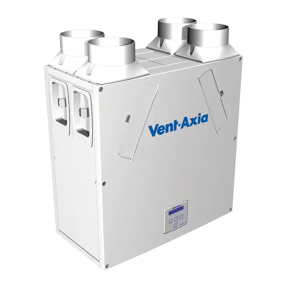
Product Description Sentinel Kinetic & Sentinel Kinetic Plus The Vent-Axia Sentinel Kinetic & Sentinel Kinetic Plus Mechanical Ventilation/Heat Recovery (MVHR) is a heat recovery unit designed for the energy efficient ventilation of houses and similar dwellings, conforming to the latest requirements of the Building Regulations document F 2010. -
Page 5: Technical Data
Operating Humidity 0% to 95% RH Storage Temperature -20C to +45C Storage Humidity 0% to 95% RH Software Version For all other technical details, please see the Product Catalogue or our website at www.vent-axia.com Sentinel Kinetic MVHR Installation & Commissioning... - Page 6 Installation ø Allow clearance to remove filter Figure 3: Sentinel Kinetic Dimensions Figure 4: Sentinel Kinetic Plus Dimensions Sentinel Kinetic MVHR Installation & Commissioning...
- Page 7 Sentinel Kinetic Range Summer By Pass Models. The Sentinel Kinetic B, BH, Plus B, Plus BS, S BH, and Plus CVP are fitted with a Summer By Pass (SBP) and will provide energy-free heating and energy-free cooling when the house temperature and ambient temperature allows.
-
Page 8: Sentinel Kinetic Performance Graph For Horizontal Discharge
Installation Sentinel Kinetic Performance graph for Vertical Discharge Volume (l/s) 100% Volume (m Sentinel Kinetic Performance graph for Horizontal Discharge Volume (l/s) 100% Volume (m3/h) Note: Graph show 2 typical system curves with total unit input power in Watts. Sentinel Kinetic MVHR Installation & Commissioning... -
Page 9: Sentinel Kinetic Plus And Plus Cvp Performance Graph For Vertical And Horizontal Discharge
Installation Sentinel Kinetic Plus and Plus CVP Performance graph for Vertical and Horizontal Discharge Volume (l/s) 100% Volume (m3/h) Note: Graph shows 2 typical system curves with total unit input power in Watts and the shaded area of the graph shows constant volume operation (CVP only). -
Page 10: Overview
Installation Installation Overview The following instructions are intended to help prevent potential hazards and installation should only be carried out by a qualified electrician and installer. This booklet covers both the Kinetic and Kinetic Plus. The control systems are identical on all units. There are some differences during the physical installation that the installer needs to be aware of. - Page 11 Installation If the orientation of the condensate exit (and the atmosphere spigots) would be better suited on the left of the unit, the front Control Unit and the rear Cable Inlet Plate can be swapped over to allow the unit to be installed in the opposite orientation.
- Page 12 Installation 4. Remove the 2 screws and detach the Electrical Cover from the front of the unit. 5. Remove the 2 screws and detach the Control Panel and disconnect the mains lead. 6. Disconnect the ribbon cable. 7. Disconnect the 4-way connector. Sentinel Kinetic MVHR Installation &...
- Page 13 Installation 8. Remove the 2 screws and detach the rear Cable Inlet Plate. Note that the grommets shown may be replaced by easy knock-out positions. If these are required ensure that you use a grommet or gland to protect against potential water ingress. See note in bold on page 20.
- Page 14 Installation 2. Remove the black Cap from the end of the condensate stub at the rear of the unit. 3. If not already fitted, fit the flexible condensate pipe and secure with worm drive clip The condensate pipe can be attached with a worm drive clip to a 22 mm vertical pipe.
- Page 15 Installation 2. Remove the Black Cap from end of condensate stub at the front of the unit. 3. On the Kinetic drill a diameter 32 mm hole where shown, right. On the Kinetic Plus drill a diameter 32 mm hole using the indent provided in the moulding as a guide.
- Page 16 Installation 5. Fit the flexible condensate pipe to a 22mm diameter x 280mm long condensate pipe with worm drive clip. 6. Fit pipe assembly into waste pipe and secure to condensate spigot with worm drive clip. Spigot Installation Air entry/exit spigots may be fitted on either the top or the side of the unit for vertical or horizontal entry or exit. Attach the spigots, depending on the space available for the ducting and orientation of the unit.
- Page 17 Installation Wall Mounting Sentinel Kinetic Refit the front and rear covers if they have been removed. Ensure four off wall bushes are fitted to the rear cover across the middle and upper screws. Mark the condensate and wall bracket positions. Fit 2-off metal wall brackets (supplied) to the wall using appropriate fixings.
- Page 18 3. Mark the condensate and wall bracket positions using the template below. A paper copy can be obtained from Vent-Axia Technical Support. 4. Fit metal wall bracket (supplied) to the wall using appropriate fixings.
- Page 19 Installation Floor Mounting Sentinel Kinetic Plus 1. Remove the front and rear covers. 2. Ensure that a secure, firm, flat and level surface is provided to place the Kinetic Plus unit on. 3. Screw down through the white plastic base plate of the unit to a board which may then be screwed to joists, flooring or equivalent.
-
Page 20: Electrical Installation
Connect any switches or sensors required to control the unit by connecting to the terminal connectors at the bottom of the control unit as shown below and in Table 1. If necessary contact Vent-Axia regarding the wiring and fixing of accessories and sensors. - Page 21 Installation Table 1: Terminal Connections Terminal No. Name Description (Control Mode 01) S/W1 Switch 1 With link fitted on J4 - activates volt-free contact for sensor input between + and - terminals S/W2 Switch 2 S/W3 Switch 3 With Vent-Wise PCB fitted to J4 - enables Vent-Wise sensor input Note do not fit standard sensors or Volt- free switch contact in this mode.
- Page 22 Installation Connecting a Boost (Light) Switch A Switched Live (LS) may be used to boost the airflow when a light is turned on, for instance in a bathroom or kitchen. If the LS core of the mains cable is not used it should be terminated in an appropriate manner. Power supplied to the unit via a 3 pole isolating switch must be supplied via the same circuit as the LS connection.
-
Page 23: Powering Up The Unit
Start Up Powering Up the Unit Switching On To switch the unit on: 1. Switch on the power at the mains supply isolator feeding the unit. 2. Following switch-on, the fan motors will start and the Control Unit will display a series of start-up screens, described below (see Start-up Screens on page 24). -
Page 24: Start-Up Screens
Start Up Start-up Screens Sentinel Kinetic Version Screen The Sentinel Kinetic Version screen displays the firmware version number for 3 seconds. No adjustments are possible on this screen. Language Screen The Language screen displays the language used for Language the screens. It is typically displayed for 5 seconds, or English longer if changing the setting. - Page 25 Start Up An interval can be set, see page 38, at which the unit reminds the user Check Filter to check the filters. The normal screen top line will include Check Filter 30 % as a reminder to check and, if necessary, clean or replace the filters. When this has been done, press and hold the buttons for 5 seconds to reset the automatic message.
- Page 26 Start Up Purge Screen Pressing and holding the button for approximately 5 Purge 120m seconds activates purge mode when you want to purge 100 % air from the building. The unit will revert to normal flow by pressing and holding the button again for 5 seconds.
- Page 27 Start Up Indoor Temp Screen From the Normal Airflow screen, simply press the Indoor Temp button until the Indoor Temp screen is displayed. 25 C The Indoor Temp screen enables you to choose the target room temperature in degrees Centigrade – only displayed when the bypass is fitted.
-
Page 28: Commissioning
Commissioning Commissioning Overview The instructions in this section are intended to provide configuration and operation information for setting up the equipment. In the event of problems, see Troubleshooting on page 44 Follow good practice when commissioning the unit. Ensure that the system is installed according to the system designers intent incorporating any acoustic ducting, that all joints are air tight, ducting is well supported, bends are avoided close to vents, and that the vent valves are fully open at the start of the commissioning process. -
Page 29: Control Unit Screens Summary
Commissioning Control Unit Screens Summary When the unit is switched on (see Powering up the Unit on page 23, the following Control Unit screens are available for monitoring and configuring the unit. Commissioning Screens PIN number set Security PIN? Start-up Screens Proportional **** Humidity... -
Page 30: Commissioning Screens
Commissioning Commissioning Screens The commissioning screens enable you to configure the operational settings of the unit. Settings are stored in a non-volatile memory and will be retained irrespective of mains supply breaks. Note: Access to the commissioning screens is prevented if the display shows Antifrost Active, Room Too Cold or a Fault Code. - Page 31 Commissioning Hood speed or below Normal speed setting. Normal Supply Screen The Normal Supply screen enables you to set the Normal Supply Normal airflow speed for the Supply fan in order to 30 % balance out any differences in ductwork or other installation features.
- Page 32 Commissioning Cooker Hood Supply Screen The Cooker Hood Supply screen enables you to set the Ckr Hood Supply Boost speed for the Supply fan. 100 % Default Cooker Hood supply speed = 30% Cooker Hood Extract Screen The Cooker Hood Extract screen enables you to set Ckr Hood Extract the Boost speed for the Extract fan.
- Page 33 Commissioning Boost On/Off Screen (Day) The Boost On/Off screen enables you to set a time for Boost On boost to be activated for each day of the week. Mon1 00:00 00:00 (Day) You can set up to three On/Off times per day, shown (On) as Day1, Day2 and Day3.
- Page 34 Commissioning Normal On/Off Screen (Day) The Normal Airflow mode can be set to run during the Normal On daytime i.e. from 6am to 11pm, the Low Airflow mode 00:00 00:00 will then run during the night from 11pm to 6pm. (Day) (On) The Normal On/Off screen enables you to set a time for...
- Page 35 Commissioning Proportional 1 Screen The Proportional 1 screen enables the conditions of the Proportional proportional sensors to be set. Humidity The unit can receive a 0-10 V proportional signal from either a humidity, CO or temperature external sensor, when connected to terminals P1. By default, the Proportion 1 input is set for a humidity sensor operation.
- Page 36 Commissioning Proportional 2 Screen By default, the Proportional 2 input is set to CO sensor Proportional operation. See Proportion 1 Screen for a description. SW4 Screen Momentary closure (1 sec) starts or stops boost for set SW4 Momentary time. Selectable range: min. = 15, max. = 30. Default = Off when no Vent-Wise card fitted.
- Page 37 Commissioning CVP Control This screen by default displays CV mode. The unit can CVP Control operate by choosing Constant Volume or Constant Pressure, or can be set to Off to run on fan curve. Default for standard unit is Off and for CVP unit is CV. Summer Bypass Screen The Summer Bypass screen is factory set if one has Summer Bypass...
- Page 38 Commissioning Filter Service Press and then use the push-buttons to Filter Service select the time between Filter Services. The options are Suburban Urban (6 months), Suburban (default: 12 months) or Rural (18 months). BMS screen On for BMS (default) or Off for Wired Remote Control, BMS Mode automatically set up by BMS signal or Wired Remote Control when either is plugged into BMS RJ11 socket.
- Page 39 Commissioning Table 3: Default Settings Parameters Settings Start-up Screens Sentinel Kinetic Sentinel Kinetic Language English. Control Mode Airflow Units Commissioning Screens Security PIN Not set Boost Supply/Extract 50 % Normal Supply/ Extract 30 % Low Supply/Extract Cooker Hood supply / extract 30% / 100% Boost Overrun Boost Delay...
-
Page 40: Maintenance
Maintenance Maintenance Heat recovery units, by their very nature, require regular maintenance. The Sentinel Kinetic has been designed to facilitate access to enable maintenance to be carried out easily. WARNING THE FAN AND ANCILLARY CONTROL EQUIPMENT MUST BE ISOLATED FROM THE POWER SUPPLY DURING MAINTENANCE. -
Page 41: Heat Exchanger Removal Instruction For Cvp Unit
Maintenance Heat Exchanger Removal Instruction for CVP Unit 1. Remove the 8 screws and detach the front cover and then pull out both filters. 2. Remove both pressure tubes from their channels and let them remain suspended in the air as shown opposite. - Page 42 Maintenance 4. Pull out the cell and make sure that the rear bottom of the cell is securely resting on the lower edge of the foam so you can access the rear pressure tube. Repeat step 3 to detach the rear pressure tube. When the rear pressure tube is removed then the cell is free to clean.
-
Page 43: Spares
Maintenance Spares The following spares may be ordered from Vent-Axia: Part No Description 441768 Main Power Board 441767 Control Panel 443430 Temperature Sensor T1 (Extract air from room) 443431 Temperature Sensor T2 (Supply air from outside) SENTINEL KINETIC SPARES 441774 Filters, 2 per pack (bypass version 438222 &... -
Page 44: Troubleshooting
Troubleshooting Troubleshooting Diagnosing a Problem In the event of a problem, always troubleshoot the unit according to: Fault code displayed on the Control Unit. Fault LED if connected. If no indications are displayed, then troubleshoot problem according to the fault symptom as described in the following tables. - Page 45 Troubleshooting Room Too Cold Screen The Room Too Cold screen displays the status of the Room Too Cold fan. If the heating system in the building fails or is Fan Off switched off and the internal temperature drops below 5°C, the unit will stop running so as to not bring cold air into an already cold house.
-
Page 46: Appendix One: Control Mode 02 Description
Appendix One Appendix One: Control Mode 02 Description Overview The functional differences described in this Appendix are available when Control Mode 02 is selected from the start-up screens. Control Mode 02 assigns alternative functions to certain wiring Terminal Connections and allows additional airflow settings to be accessed via the button on the front of the Kinetic unit or remote control. -
Page 47: Airflow Mode Selection
Appendix One Airflow Mode Selection The following switching Functions are available via the button with Control Mode 02: No. of presses Airflow Mode (Control Mode 02) Normal Boosts 30 minutes Boosts 60 minutes Boosts continuously Cancel Press 10 seconds after last press to cancel and return to normal operation. If the wireless boost option is fitted, this can be triggered from the wireless transmitter/boost switch. -
Page 48: Appendix Two: Options And Accessories
Appendix Two Appendix Two: Options and Accessories CO2 Sensor An optional wall-mounted CO Sensor (433257) may be used to control airflow. The CO sensor measures the level in ppm (parts per million) and the unit adjusts the fan speed accordingly. When the CO level is below the lower threshold (adjustable), the fan will run at Normal speed. -
Page 49: Wireless Enable Kit
Appendix Two Wireless Enable Kit (consists of Wireless Receiver and one Wireless Switch) (441865) To fit the Wireless Receiver remove the Front, Rear and Bottom Case panels, insert the ribbon cable plug into terminal J9 and fit the Receiver assembly to the main PCB with the double sided pads provided. Wireless Receiver 2. -
Page 50: Wired Remote Control
Appendix Two Wired Remote Control (443283) 1. The Wired Remote Control uses 15 metre long cable and has the same functionality as the control mounted on the unit, it can be permanently mounted in a living space for the end user or used for commissioning the unit. - Page 51 Appendix Two Sentinel Kinetic MVHR Installation & Commissioning...
- Page 52 Applicable only to products installed and used in the United Kingdom. For details of guarantee outside the United Kingdom contact your local supplier. Vent-Axia guarantees its products for two years from date of purchase against faulty material or workmanship. In the event of any part being found to be defective, the product will be repaired, or at the Company’s option replaced, without charge, provided that the product:-...
Need help?
Do you have a question about the Sentinel Kinetic B and is the answer not in the manual?
Questions and answers
The unit is displaying Fault code F-01 and sometimes P-01
Fault code F-01 means the supply fan is not running. Fault code P-01 is not defined in the provided information.
This answer is automatically generated