Vent-Axia Sentinel Kinetic V Installation & Commissioning Manual
Mvhr range kinetic series
Hide thumbs
Also See for Sentinel Kinetic V:
- Installation & commissioning (52 pages) ,
- Operation manual (20 pages)
Table of Contents
Advertisement
Sentinel
Kinetic MVHR Range
Installation & Commissioning
PLEASE RETAIN THESE INSTRUCTIONS WITH THE PRODUCT.
Stock Ref. N°
438342 Kinetic V
438222 Kinetic B Right
438222L Kinetic B Left
443319 Kinetic BH Right
443319L Kinetic BH Left
408167 Kinetic FH Right
408169 Kinetic FH Left
443028 Kinetic Plus B Right
443028L Kinetic Plus B Left
408449 Kinetic High Flow Right
408451 Kinetic High Flow Left
Copyright © 2009 Vent-Axia Limited. All rights reserved.
Advertisement
Table of Contents

Related Manuals for Vent-Axia Sentinel Kinetic V


Summary of Contents for Vent-Axia Sentinel Kinetic V
- Page 1 408167 Kinetic FH Right 408169 Kinetic FH Left 443028 Kinetic Plus B Right 443028L Kinetic Plus B Left 408449 Kinetic High Flow Right 408451 Kinetic High Flow Left PLEASE RETAIN THESE INSTRUCTIONS WITH THE PRODUCT. Copyright © 2009 Vent-Axia Limited. All rights reserved.
-
Page 2: Important Safety Information
Warnings & Safety Information IMPORTANT SAFETY INFORMATION 8. Young children should be supervised to PLEASE READ THESE ensure that they do not play with the INSTRUCTIONS CAREFULLY appliance. BEFORE COMMENCING INSTALLATION. INSTALLATION GUIDANCE 1. Do not install this product in areas where 1. -
Page 3: Table Of Contents
About this Document Contents IMPORTANT SAFETY INFORMATION ......... 2 INSTALLATION GUIDANCE ............2 Product Description Sentinel Kinetic, Sentinel Kinetic F, Sentinel Kinetic Plus & Sentinel Kinetic High Flow................5 Technical Data Sentinel Kinetic Performance graph for Horizontal Discharge ..10 Sentinel Kinetic F Performance graph for Vertical and Horizontal ... - Page 4 About this Document UK Building Regulations (Part F) Declaration of Conformance The Sentinel Kinetic conforms to the 2010 Building Regulations (Part F - Means of Ventilation requirements) for installed performance of a ducted mechanical extract fan when installed in accordance with the instructions in this document.
-
Page 5: Product Description
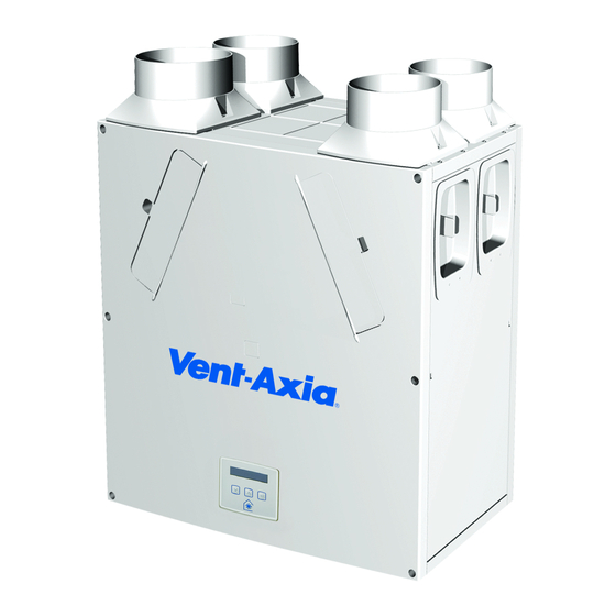
Sentinel Kinetic, Sentinel Kinetic F, Sentinel Kinetic Plus & Sentinel Kinetic High Flow The Vent-Axia Sentinel Kinetic, Sentinel Kinetic F, Sentinel Kinetic Plus & Sentinel Kinetic High Flow Mechanical Ventilation/Heat Recovery (MVHR) are heat recovery units designed for the energy efficient ventilation of houses and similar dwellings, conforming to the latest requirements of the Building Regulations document F 2010. - Page 6 Product Description Models 438342 - Sentinel Kinetic V without summer bypass. 438222 - Sentinel Kinetic B Right right handed with summer bypass. 438222L - Sentinel Kinetic B Left left handed with summer bypass. 443319 - Sentinel Kinetic BH Right right handed with summer bypass and integral humidity sensor.
-
Page 7: Technical Data
Operating 0% to 95% RH Humidity Storage -20C to +45C Temperature Storage Humidity 0% to 95% RH Software Version For all other technical details, please see the Product Catalogue or our website at www.vent-axia.com Sentinel Kinetic MVHR Installation & Commissioning... - Page 8 Installation Figure 5: Sentinel Kinetic Dimensions Figure 6: Sentinel Kinetic Plus and Sentinel Kinetic High Flow Dimensions Sentinel Kinetic MVHR Installation & Commissioning...
- Page 9 Installation Sentinel Kinetic Range Summer By Pass Models. The Sentinel Kinetic B, BH, Plus B, Plus BS and S BH are fitted with a Summer By Pass (SBP) and will provide energy-free cooling when the house temperature and ambient temperature allows. Note that the volume of air provided by this ventilation system is a fraction of that required for space heating or space cooling and will not in itself be sufficient to cool a room.
-
Page 10: Sentinel Kinetic Performance Graph For Horizontal Discharge
Installation Sentinel Kinetic Performance graph for Vertical Discharge Volume (l/s) 100% Volume (m Sentinel Kinetic Performance graph for Horizontal Discharge Volume (l/s) 100% Volume (m3/h) Note: Graphs show 2 typical system curves with total unit input power in Watts. Sentinel Kinetic MVHR Installation & Commissioning... -
Page 11: Sentinel Kinetic F Performance Graph For Vertical And Horizontal Discharge
Installation Sentinel Kinetic F Performance graph for Vertical and Horizontal Discharge Sentinel Kinetic MVHR Installation & Commissioning... -
Page 12: Sentinel Kinetic Plus Performance Graph For Vertical And Horizontal Discharge
Installation Sentinel Kinetic Plus Performance graph for Vertical and Horizontal Discharge Note: Graph shows 2 typical system curves with total unit input power in Watts Sentinel Kinetic High Flow Performance graph for Vertical and Horizontal Discharge Volume (l/s) 1000 100% Volume (m Sentinel Kinetic MVHR Installation &... -
Page 13: Before Installation Of The Unit
Installation Installation NOTE: we advise installers to fix all mains and sensor wiring along with any internal accessories prior to fixing the MVHR unit in position, leaving approximately 500 mm tails to allow for internal routing. Before Installation of the Unit Inspect the Unit When taking delivery of the unit, check the items delivered against the enclosed delivery note. - Page 14 Installation Vertical Discharge Condensate Installation Note The 22 mm diameter condensate pipe is suitable for standard 22 mm plastic push-fit fittings and can be connected vertically underneath the unit or horizontally at the rear. To install the vertical discharge condensate: 1.
- Page 15 Installation Horizontal Discharge Condensate Installation To install the condensate horizontal discharge: 1. For horizontal discharge, remove the front cover and locate the condensate stub at the front of the unit. 2. Remove the Black Cap from end of condensate stub at the front of the unit. 3.
- Page 16 Installation 4. N.B. SEE “WALL MOUNTING” on page 17 for information on marking out the wall for the position of the condensate drain and wall mounting brackets. Fit Vertical discharge 32mm waste pipe (fitted with 22 / 32mm reducer ). Fit a ‘U’...
- Page 17 Installation Spigot Installation Air entry/exit spigots may be fitted on either the top or the side of the unit for vertical or horizontal entry or exit. Attach the spigots, depending on the space available for the ducting and orientation of the unit. Always fit the blanking caps to the entry or exit hole not in use to ensure the correct airflow into and out of the unit.
- Page 18 Installation Wall Mounting Sentinel Kinetic L/H CONDENSATE R/H CONDENSATE EXIT 213 EXIT 213 Sentinel Kinetic MVHR Installation & Commissioning...
- Page 19 Installation Wall Mounting Sentinel Kinetic Plus & Sentinel Kinetic High Flow 1. Refit the front and rear covers if they have been removed. 2. Ensure the three steel wall bushes are fitted to the rear cover, along the top row of screws. 3.
- Page 20 Installation Floor Mounting Sentinel Kinetic Plus and Kinetic High Flow 1. Remove the front and rear covers. 2. Ensure that a secure, firm, flat and level surface is provided to place the Kinetic Plus unit on. 3. Screw down through the white plastic base plate of the unit to a board which may then be screwed to joists, flooring or equivalent.
-
Page 21: Electrical Installation
Connect any switches or sensors required to control the unit by connecting to the terminal connectors at the bottom of the control unit as shown below and in Table 1. If necessary contact Vent-Axia regarding the wiring and fixing of accessories and sensors. - Page 22 Installation Table 1: Terminal Connections Terminal No. Name Description (Control Mode 01) S/W1 Switch 1 With link fitted on J4 - activates volt-free contact for sensor input between + and - terminals S/W2 Switch 2 S/W3 Switch 3 With Vent-Wise PCB fitted to J4 - enables Vent-Wise sensor input Note do not fit standard sensors or Volt- free switch contact in this mode.
- Page 23 If the LS core of the mains cable is not used it should be terminated in an appropriate manner. NOTES Power supplied to the unit via a 3 pole isolating switch, such as Vent-Axia Part Number 563518, must be supplied via the same circuit as the LS connection. Alternatively an isolator relay controller, part number 442030, may be used.
-
Page 24: Powering Up The Unit
Commissioning Powering Up the Unit Switching On To switch the unit on: 1. Switch on the power at the mains supply isolator feeding the unit. 2. Following switch-on, the fan motors will start and the Control Unit will display a series of start-up screens, described below (see Start-up Screens on page 25). -
Page 25: Start-Up Screens
Commissioning Start-up Screens (Refer to Control Mode 01 unless otherwise indicated) Sentinel Kinetic Version Screen The Sentinel Kinetic Version screen displays the firmware version number for 3 seconds. No adjustments are possible on this screen. Language Screen The Language screen displays the language used for Language the screens. - Page 26 Commissioning Normal Airflow If Control Mode 02 has been selected then the Normal Airflow screen Auto includes either “Auto” or “Manual” to indicate if the boost level has been triggered by the button on the controller or automatically via a sensor. When the summer bypass is active, the normal screen top line will Summer Bypass On alternate (for 3 seconds) with Summer Bypass On.
- Page 27 Commissioning Pressing the button activates the boost airflow mode when extra Boost Airflow ventilation is required. 50 % No. of presses Boost action (Control Mode 01) Boosts for 30 minutes Boosts for 60 minutes Boosts continuously Back to Normal flow rate N.B Additional airflow modes are available from the button when Control Mode 02 is selected in the start-up screens see...
- Page 28 Commissioning Purge Screen Pressing and holding the button for approximately 5 Purge 120m seconds activates purge mode when you want to purge 100 % air from the building. The unit will revert to normal flow by pressing and holding the button again for 5 seconds.
- Page 29 Commissioning Indoor Temp Screen From the Normal Airflow screen, simply press the Indoor Temp button until the Indoor Temp screen is displayed. 25 C The Indoor Temp screen enables you to choose the target room temperature in degrees Centigrade – only displayed when the bypass is fitted.
-
Page 30: Commissioning
Commissioning Commissioning Overview The instructions in this section are intended to provide configuration and operation information for setting up the equipment. In the event of problems, see Troubleshooting on page 45 Follow good practice when commissioning the unit. Ensure that the system is installed according to the system designers intent incorporating any acoustic ducting, that all joints are air tight, ducting is well supported, bends are avoided close to vents, and that the vent valves are fully open at the start of the commissioning process. -
Page 31: Control Unit Screens Summary
Commissioning Control Unit Screens Summary When the unit is switched on (see Powering up the Unit on page 24, the following Control Unit screens are available for monitoring and configuring the unit. Commissioning Screens PIN number set Proportional Security PIN? Humidity Start-up Screens ****... -
Page 32: Commissioning Screens
Commissioning Control Unit Screens Overview Commissioning Screens The commissioning screens enable you to configure the operational settings of the unit. Settings are stored in a non-volatile memory and will be retained irrespective of mains supply breaks. Note: Access to the commissioning screens is prevented if the display shows Antifrost Active, Room Too Cold or a Fault Code. - Page 33 Commissioning Normal Supply Screen The Normal Supply screen enables you to set the Normal Supply Normal airflow speed for the Supply fan in order to 30 % balance out any differences in ductwork or other installation features. Default Normal speed = 30% See graph on either page 10, 11 or 12 for setting the Supply airflow.
- Page 34 Commissioning Cooker Hood Supply Screen The Cooker Hood Supply screen enables you to set the Ckr Hood Supply Boost speed for the Supply fan. 100 % Default Cooker Hood supply speed = 30% Cooker Hood Extract Screen The Cooker Hood Extract screen enables you to set Ckr Hood Extract the Boost speed for the Extract fan.
- Page 35 Commissioning Boost On/Off Screen (Day) The Boost On/Off screen enables you to set a time for Boost On boost to be activated for each day of the week. Mon1 00:00 00:00 (Day) You can set up to three On/Off times per day, shown (On) as Day1, Day2 and Day3.
- Page 36 Commissioning Normal On/Off Screen (Day) The Normal Airflow mode can be set to run during the Normal On daytime i.e. from 6am to 11pm, the Low Airflow mode 00:00 00:00 will then run during the night from 11pm to 6pm. (Day) (On) The Normal On/Off screen enables you to set a time for...
- Page 37 Commissioning Proportional 1 Screen The Proportional 1 screen enables the conditions of the Proportional proportional sensors to be set. Humidity The unit can receive a 0-10 V proportional signal from either a humidity, CO or temperature external sensor, when connected to terminals P1. By default, the Proportion 1 input is set for a humidity sensor operation.
- Page 38 Commissioning Proportional 2 Screen By default, the Proportional 2 input is set to CO sensor Proportional operation. See Proportion 1 Screen for a description. SW4 Screen Momentary closure (1 sec) starts or stops boost for set SW4 Momentary time. Selectable range: min. = 15, max. = 30. Default = Off when no Vent-Wise card fitted.
- Page 39 Commissioning Boost Button Boost Button The Boost Button screen allows the boost button on the front of the unit and on a remote control, if fitted, to be disabled by setting to Off. When set to Off this also disables the Purge function. Available options = On (default) and Off.
- Page 40 Commissioning Pre Heater Screen (Currently unavailable option) If an electrical pre heater is being used in conjunction Pre Heater with the anti-frost system to prevent freezing of the heat recovery cell then this is set to On. The pre heater control must be wired up according to its instructions.
- Page 41 Commissioning Security PIN Screen The Security PIN screen enables you top set a four-digit Security PIN? personal identification number (PIN) to access the commissioning screens. This screen will show blank if security is disabled and no PIN is used. Press to reveal 0000 with the first 0 flashing and use buttons to change the selection (0-9).
- Page 42 Commissioning Table 3: Default Settings Parameters Settings Start-up Screens Sentinel Kinetic Sentinel Kinetic Language English. Control Mode Airflow Units Commissioning Screens Security PIN Not set Boost Supply/Extract 50 % Normal Supply/ Extract 30 % Low Supply/Extract Cooker Hood 30% / 100% supply / extract Boost Overrun Boost Delay...
-
Page 43: Maintenance
Maintenance Maintenance Heat recovery units, by their very nature, require regular maintenance. The Sentinel Kinetic has been designed to facilitate access to enable maintenance to be carried out easily. WARNING THE FAN AND ANCILLARY CONTROL EQUIPMENT MUST BE ISOLATED FROM THE POWER SUPPLY DURING MAINTENANCE. -
Page 44: Spares
Maintenance Spares The following spares may be ordered from Vent-Axia: Part No Description 441768 Main Power Board 441767 Control Panel 443430 Temperature Sensor T1 (Extract air from room) 443431 Temperature Sensor T2 (Supply air from outside) SENTINEL KINETIC SPARES 441774 G3 Filters, 2 per pack (bypass version 438222 &... -
Page 45: Troubleshooting
Troubleshooting Troubleshooting Diagnosing a Problem In the event of a problem, always troubleshoot the unit according to: Fault code displayed on the Control Unit. Fault LED if connected. If no indications are displayed, then troubleshoot problem according to the fault symptom as described in the following tables. - Page 46 Troubleshooting Room Too Cold Screen The Room Too Cold screen displays the status of the Room Too Cold fan. If the heating system in the building fails or is Fan Off switched off and the internal temperature drops below 5°C, the unit will stop running so as to not bring cold air into an already cold house.
-
Page 47: Appendix One: Control Mode 02 Description
Appendix One Appendix One: Control Mode 02 Description Overview The functional differences described in this Appendix are available when Control Mode 02 is selected from the start-up screens. Control Mode 02 assigns alternative functions to certain wiring Terminal Connections and allows additional airflow settings to be accessed via the button on the front of the Kinetic unit or remote control. -
Page 48: Airflow Mode Selection
Appendix One Airflow Mode Selection The following switching Functions are available via the button with Control Mode 02: No. of presses Airflow Mode (Control Mode 02) Normal Boosts 30 minutes Boosts 60 minutes Boosts continuously Cancel Press 10 seconds after last press to cancel and return to normal operation. If the wireless boost option is fitted, this can be triggered from the wireless transmitter/boost switch. -
Page 49: Appendix Two: Options And Accessories
Appendix Two Appendix Two: Options and Accessories CO2 Sensor An optional wall-mounted CO Sensor (433257) may be used to control airflow. The CO sensor measures the level in ppm (parts per million) and the unit adjusts the fan speed accordingly. When the CO level is below the lower threshold (adjustable), the fan will run at Normal speed. -
Page 50: Wireless Enable Kit (Consists Of Wireless Receiver And One Wireless Switch) (441865)
Appendix Two Connect the pair of leads from the BMS to the terminal block of the opto-coupler pcb. Polarity does not matter here. Wireless Enable Kit (consists of Wireless Receiver and one Wireless Switch) (441865) To fit the Wireless Receiver remove the Front, Rear and Bottom Case panels, insert the ribbon cable plug into terminal J9 and fit the Receiver assembly to the main PCB with the double sided pads provided. -
Page 51: Wired Remote Control (443283)
Appendix Two Wired Remote Control (443283) 1. The Wired Remote Control uses 15 metre long cable and has the same functionality as the control mounted on the unit, it can be permanently mounted in a living space for the end user or used for commissioning the unit. -
Page 52: Remote Led Indicator (448347)
Appendix Two Remote LED Indicator (448347) The LED terminals are intended to drive a remote LED to indicate that there is a message in the control display. They provide a 5 V LED driving signal output between the + and – terminals that enables remote indication of filter check or unit fault.
Need help?
Do you have a question about the Sentinel Kinetic V and is the answer not in the manual?
Questions and answers