Vent-Axia sentinel Kinetic MVHR series User Instructions
Hide thumbs
Also See for sentinel Kinetic MVHR series:
- Installation & commissioning manual (53 pages) ,
- Installation instructions manual (6 pages) ,
- Installation & commissioning manual (48 pages)
Table of Contents
Advertisement
V:\Technical\ARTWORK\Fitting & Wiring\Word Files HOLDING\442073 V.doc
Sentinel
Kinetic MVHR RANGE
User Instructions
SEE PAGE 16 FOR SPARE FILTERS
PLEASE RETAIN THESE INSTRUCTIONS WITH THE PRODUCT.
442073 VCopyright © 2009 Vent-Axia Limited. All rights reserved.
Stock Ref. N°
438342
Kinetic V
438222
Kinetic B Right
438222L Kinetic B Left
443319
Kinetic BH Right
443319L Kinetic BH Left
408167
Kinetic FH Right
408169
Kinetic FH Left
443028
Kinetic Plus B Right
443028L Kinetic Plus B Left
408449
Kinetic High Flow Right
408451
Kinetic High Flow Left
Advertisement
Table of Contents

Related Manuals for Vent-Axia sentinel Kinetic MVHR series


Summary of Contents for Vent-Axia sentinel Kinetic MVHR series
-
Page 1: User Instructions
Kinetic Plus B Right 443028L Kinetic Plus B Left 408449 Kinetic High Flow Right 408451 Kinetic High Flow Left SEE PAGE 16 FOR SPARE FILTERS PLEASE RETAIN THESE INSTRUCTIONS WITH THE PRODUCT. 442073 VCopyright © 2009 Vent-Axia Limited. All rights reserved. -
Page 2: Table Of Contents
SAFETY INFORMATION AND CONTENTS IMPORTANT SAFETY INFORMATION Contents PLEASE READ THESE IMPORTANT SAFETY INFORMATION ......... 2 PLEASE READ THESE NEW PROPERTY FILTER MAINTENANCE ......... 2 INSTRUCTIONS CAREFULLY INSTRUCTIONS CAREFULLY BEFORE USING THE UNIT. BEFORE USING THE UNIT. Product Description ... -
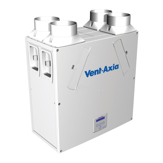
Page 3: Product Description
Sentinel Kinetic Sentinel Kinetic F Sentinel Kinetic Plus & Sentinel Kinetic High Flow The Vent-Axia Sentinel Kinetic, Sentinel Kinetic F, Sentinel Kinetic Plus & Sentinel Kinetic High Flow Mechanical Ventilation/Heat Recovery (MVHR) are heat recovery units designed for the energy efficient ventilation of houses and similar dwellings, conforming to the latest requirements of the Building Regulations document F 2010. - Page 4 Technical Specification Sentinel Kinetic Range Summer By Pass Models. The Sentinel Kinetic B, BH, FH, Plus B, Plus BH and High Flow are fitted with a Summer By Pass (SBP) and will provide energy-free cooling when the house temperature and ambient temperature allows. Note that the volume of air provided by this ventilation system is a fraction of that required for space heating or space cooling and will not in itself be sufficient to cool a room.
- Page 5 Technical Specification Models 438342 - Sentinel Kinetic V without summer bypass. 438222 - Sentinel Kinetic B Right right handed with summer bypass. 438222L - Sentinel Kinetic B Left left handed with summer bypass. 443319 - Sentinel Kinetic BH Right right handed with summer bypass and integral humidity sensor. ...
-
Page 6: Control Unit Display
Technical Specification Control Unit Display The Control Unit is located at the front of the Sentinel Kinetic unit. The Control Unit provides the user interface for commissioning and monitoring purposes. Figure 3: Control Unit Display The main display is an LCD with automatic backlight, Normal Airflow which is turned off to minimise power consumption when the unit is operational (see Overview on page 9). - Page 7 Temperature Operating 0% to 95% RH Humidity Storage -20C to +45C Temperature Storage Humidity 0% to 95% RH Software Version For all other technical details, please see the Product Catalogue or our website at www.vent-axia.com. Sentinel Kinetic MVHR User Instructions...
-
Page 8: Powering Up The Unit
Starting Up Powering Up the Unit Switching On (The unit is designed to run continuously) To switch the unit on: Switch on the power at the mains supply isolator feeding the unit. Following switch-on, the fan motors will start and the Control Unit will display a series of startup screens, described below. -
Page 9: Operation And Monitoring
Operation and Monitoring Operation and Monitoring Overview When the Sentinel Kinetic unit has been installed and commissioned it should require no further intervention in order to operate, unless external switches are used to control on/off/boost, etc, or BMS control requires user action. Start-up Screens Language English... -
Page 10: User Menu Screens
Operation and Monitoring User Menu Screens From the Normal Airflow screen, press the button to access the rest of the User Menu screens. Changing the value of a setting (if adjustable) is typically a 3-step procedure: Press to select the setting (the setting will flash). Use the buttons to adjust the value. - Page 11 Operation and Monitoring Set Clock Screen From the Normal Airflow screen, simply press the Set Clock button once to access the Set Clock screen. Mon 12:30 The Set Clock Control screen enables you to change the clock settings. The clock retains its settings for approximately two weeks without mains power, after which it will need resetting when power is reconnected Values are DDD HH:MM.
-
Page 12: Boost & Purge Screens
Operation and Monitoring Boost & Purge Screens Boost Screen Pressing the button activates boost airflow mode Boost Airflow when extra ventilation is required. 50 % No. of presses Boost action (Control Mode 01) Boosts for 30 minutes Boosts for 60 minutes Boosts continuously Back to Normal flow rate N.B Additional airflow modes are available from the... -
Page 13: Status Message Screens
Operation and Monitoring Purge Screen Pressing and holding the button for 5 seconds Purge 120m activates purge mode when you want to purge air from 100 % the building. The unit will revert to normal flow by pressing and holding the button again for 5 seconds. - Page 14 Operation and Monitoring Defrost Active Screen The Antifrost screen is only displayed if a summer Defrost Active bypass is fitted. In installations where a negative Airflow Mode pressure is not permitted during antifrost operation, set this to bypass mode. Available options: Airflow Mode (default) and Bypass Mode.
-
Page 15: Maintenance
Troubleshooting Maintenance Caring for the Unit Heat recovery units, by their very nature, require regular maintenance. The Sentinel Kinetic has been designed to facilitate access to enable maintenance to be carried out easily. Filter Maintenance Item Action Fan Filters When the unit displays “Check filters”. This is a reminder to ensure that the filters are not so dirty that they are blocking the airflow or allowing dirt to pass through. - Page 16 443352 Heat Recovery Cell 409776 Supply Motor 409778 Extract Motor 443355 Summer Bypass 446523 Spigot diameter 180 mm, one per pack, complete with foam adaptor to make 200mm spigot. SALES ENQUIRIES: www.vent-axia.com Tel: 0344 8560590 Sentinel Kinetic MVHR User Instructions...
-
Page 17: Troubleshooting
Troubleshooting Troubleshooting Diagnosing a Problem In the event of a problem, always troubleshoot the unit according to: Fault code displayed on the Control Unit or Remote Wired Control. Fault LED if connected. If no indications are displayed, then troubleshoot problem according to the fault symptom as described in the following tables. -
Page 18: Appendix One: Control Mode 02 Description Overview
Appendix One Appendix One: Control Mode 02 Description Overview The functional differences described in this Appendix are available when Control Mode 02 is selected from the start-up screens. Control Mode 02 assigns alternative functions to certain wiring Terminal Connections (described in Appendix One of the Installation and Commissioning Manual) and allows additional airflow settings to be accessed via the button on the front of the Kinetic unit or remote control as shown below: Airflow Mode Selection... -
Page 19: Appendix Two: Spare Filters
Appendix Two Appendix Two: Spare Filters Model Filter Part no. Grade 442356 (PK2) Kinetic V,B & BH 444199 (Single) 409764 (PK2) Kinetic FH 472153 (Single) Kinetic Plus and Kinetic High Flow 403702 (PK2) 444201 (Single) - Page 20 Applicable only to products installed and used in the United Kingdom. For details of guarantee outside the United Kingdom contact your local supplier. Vent-Axia guarantees its products for two years from date of purchase against faulty material or workmanship. In the event of any part being found to be defective, the product will be repaired, or at the Company’s option replaced, without charge, provided that the product:-...
Need help?
Do you have a question about the sentinel Kinetic MVHR series and is the answer not in the manual?
Questions and answers
how to remove the top spigots such that they can be placed on the side of the unit. the side plates look to be simply screwed on but how are the top spigots fixed?
the unit bis a left hand vent axia high flow.
To remove the top spigots on a Vent-Axia Sentinel Kinetic MVHR series unit and install them on the side:
1. Unscrew the screw(s) securing the spigot to the chassis.
2. Firmly pull the spigot from the entry/exit hole.
3. Unscrew the screw(s) securing the blanking cap on the side.
4. Firmly pull the blanking cap from the entry/exit hole.
5. Swap the spigot with the removed blanking cap.
6. Insert the spigot into the side entry/exit hole and secure it with the retaining screw(s).
7. Insert the blanking cap into the top entry/exit hole and secure it with the retaining screw(s).
This answer is automatically generated