Table of Contents
Advertisement
Advertisement
Table of Contents
Troubleshooting

Related Manuals for MINN KOTA ULTREX QUEST


Summary of Contents for MINN KOTA ULTREX QUEST
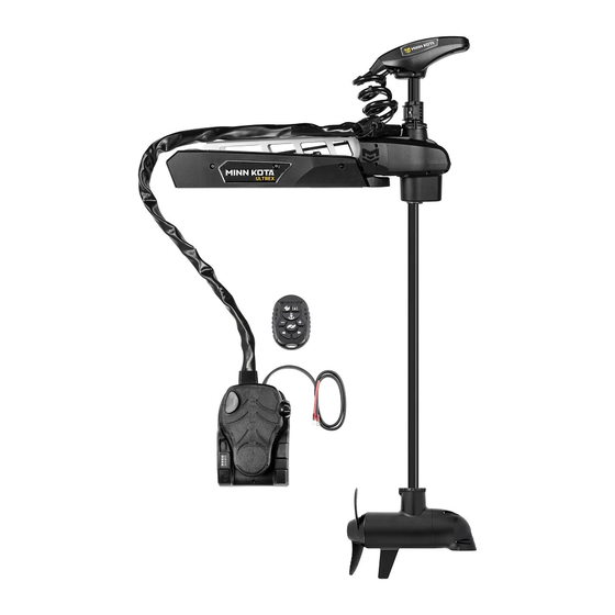
- Page 1 ® ULTREX QUEST BOW-MOUNT TROLLING MOTOR Owner's Manual...
- Page 2 Countless hours of research and testing provide you the Minn Kota advantage that can truly take you “Anywhere. Anytime.” We don’t believe in shortcuts. We are Minn Kota. And we are never done helping you catch more fi sh.
-
Page 3: Table Of Contents
Removal of the Steering Module .......... 95 ONE-BOAT NETWORK ...................68 Disconnect the Gas Springs ..........95 Optimizing the Performance of the Ultrex QUEST with Remove Motor from Mount ..........96 the One-Boat Network App ..........68 Reassemble the Steering Module ........97 One-Boat Network Adjustments .......... -
Page 4: Safety Considerations
WArning You are responsible for the safe and prudent operation of your vessel. We have designed your Minn Kota product to be an accurate and reliable tool that will enhance boat operation and improve your ability to catch fi sh. This product does not relieve you from the responsibility for safe operation of your boat. -
Page 5: Warranty
Minn Kota Limited Lifetime Warranty on Composite Shaft and Foot Pedal Cables JOME warrants to the original retail purchaser only that the composite shaft and foot pedal cables of the purchaser’s Minn Kota trolling motor will be materially free from defects in materials and workmanship appearing within the original purchaser’s lifetime. JOME will provide a new composite shaft and/or foot pedal cable, free of charge, to replace any composite shaft and/or foot pedal cable found by JOME to be defective during the term of this warranty. -
Page 6: Know Your Boat
KNOW YOUR BOAT Port Port Starboard Starboard Inboard Inboard Outboard Outboard Keel Keel Port Port Starboard Starboard Gunwale Gunwale Transom Transom Stern Stern Gunwale Gunwale Stern Stern Hull Hull 6 | minnkota.johnsonoutdoors.com ©2023 Johnson Outdoors Marine Electronics, Inc. -
Page 7: Features
FEATURES Advanced GPS Advanced GPS Navigation Navigation Pull Grip and Cable Pull Grip and Cable Depth Collar Depth Collar Outer Arm Outer Arm Steering Module Steering Module Lift-Assist Lift-Assist Lifetime Warranty Lifetime Warranty High-Impact High-Impact Flexible Composite Shaft Flexible Composite Shaft Composite Material Composite Material Momentary... -
Page 8: Installation
Quest Your new Ultrex QUEST comes with everything you’ll need to install it to the boat. This motor can be directly mounted to the boat or coupled with a Minn Kota quick release bracket for ease of mounting and removal. For installation with a quick release bracket, refer to the installation instructions provided with the bracket. -
Page 9: Assembly Of Steering Module To Mount
Assembly of Steering Module to Mount ITEM(S) NEEDED #A x 1 The Power Cables for the Ultrex QUEST trolling motor exit the Foot Pedal. The Foot Pedal is a part of Foot Pedal Foot Pedal the Motor Assembly (Assembly #A) and is attached... - Page 10 Assembly of steering module to mount ITEM(S) NEEDED #D x 1 or #E x 1 Place the Mount (Assembly #D or #E) on an Allen Screws Allen Screws elevated, level surface such as a workbench or the tailgate of a pickup. The Mount, as removed from Pull Grip Pull Grip Deployed...
- Page 11 Assembly of steering module to mount Ensure the Steering Module is fully seated before securing. Steering Steering WArning Module Module Mount Mount Carefully lower the Steering Module into place to avoid creating a pinch point between the Steering Module and Mount. Reinstall the two 5/16"...
-
Page 12: Installing The Bow-Mount
Place the Hold-Down Strap (Item #14) under the base of the Mount Plate so that it is below the Mount when placed. NOTICE: This motor weighs approximately 78 lbs. Minn Kota recommend having a second person help with Mount Mount the installation. NOTICE: Check that the Motor can properly stow and deploy at the intended mounting location. - Page 13 instAlling the boW-mount Install the Mount on either the Port or Starboard side If personal preference is to mount the motor on NOTICE: of the bow, based on personal preference. Test the the starboard side of the boat, please see the "Rotate the placement of the Hold-Down Strap to be sure it can Pedal Control Sleeve Assembly for a Starboard Mount"...
- Page 14 Hold-Down Strap is set. NOTICE: Larger mounting holes are required for customers upgrading from an Ultrex to an Ultrex QUEST. Larger mounting holes will accommodate the higher thrust motor and ensure the installation is secure. ITEM(S) NEEDED...
-
Page 15: Installing The Gas Springs
Installing the Gas Springs The Ultrex QUEST contains two Gas Springs inside the Mount. The Gas Springs work to enable Lift-Assist in both the stowed and deployed directions and are located inside the Outer Arm, a part of the Mount. At this point in the installation, the Gas Springs are not fully assembled and may move around inside the Mount when stowing and deploying the motor. - Page 16 instAlling the gAs sPrings ITEM(S) NEEDED #20 x 2 Two Gas Springs are located inside the Outer Arm. Paper Paper Once the motor is correctly positioned, the Gas Tube Tube (discard) (discard) Springs can be secured. Start with the larger Gas Bracket Bracket Outer...
-
Page 17: Battery & Wiring Installation
CAution These guidelines apply to general rigging to support your Minn Kota motor. Powering multiple motors or additional electrical devices from the same power circuit may impact the recommended conductor gauge and circuit breaker size. If you are using wire longer than that provided with your unit, follow the conductor gauge and circuit breaker sizing table below. -
Page 18: Selecting The Correct Batteries
Lithium Ion batteries, manufacturers may recommend storing in a semi-charged state and charging fully prior to use. If using a crank battery to start a gasoline outboard, Minn Kota recommends using a separate battery/batteries for your Minn Kota trolling motor. Always check with the battery manufacturer for specific maintenance, care and storage instructions. Minn Kota also offers a wide selection of chargers to fit your charging needs. -
Page 19: Connecting The Batteries In Series
Additional Accessories Connected to Trolling Motor Batteries Significant damage to your Minn Kota motor, your boat electronics, and your boat can occur if incorrect connections are made between your trolling motor batteries and other battery systems. Minn Kota recommends using an exclusive battery system for your trolling motor. - Page 20 ConneCting the bAtteries in series 36-Volt Systems Three 12-volt batteries are required. The batteries must be wired in series, only as directed in the wiring diagram, to provide 36 volts. Make sure that the motor is switched +36 Volts to trolling motor off (speed selector on “0”).
-
Page 21: Completing The Installation
Each time the trolling motor is powered "on," the control board will auto-detect the power supplied from the battery system and adjust the thrust output based on a 24V or 36V battery system. To complete the remaining installation steps, connect the Ultrex QUEST to power. At specifi c points in the installation, power is disconnected or turned "off "... -
Page 22: Indexing The Motor For A Port Installation
Indexing the Motor for a Port Installation The Ultrex QUEST comes from the factory with the Pedal Control Sleeve Assembly set inboard for a Port installation. The recommendation for correct indexing of the trolling motor is to have the Pedal Control Sleeve Assembly, which attaches the Foot Pedal to the Mount, pointing inboard. - Page 23 indexing the motor for A Port instAllAtion With the Control Head positioned parallel with the keel or centerline of the boat, the top of the Foot Keel Keel Control Head Control Head Pedal will likely not be parallel with the Boat Deck.
- Page 24 indexing the motor for A Port instAllAtion Once the two Clips and four screws are free, lift the Coil Cord Cover up and away from the Pedal Control Sonar Cable Sonar Cable Sleeve Assembly. Set the Coil Cord Cover aside for reassembly later. NOTICE: Any Sonar or Ethernet Cables previously Coil...
- Page 25 indexing the motor for A Port instAllAtion Find the two wire connections inside the Pedal Pedal Control Pedal Control Control Sleeve Assembly. One has a white Clip Sleeve Assembly Sleeve Assembly and the other has a black Clip. The Clips for both Two Wire Connections Two Wire Connections connections are located between the Steering...
- Page 26 indexing the motor for A Port instAllAtion On the Foot Pedal, locate the Cable Tension Screw Toe End of Toe End of under the base of the Toe End of the Foot Pedal. Foot Pedal Foot Pedal The Cable Tension Screw holds tension on the Steering Cables.
- Page 27 indexing the motor for A Port instAllAtion Once the Cable Tension Screw on the Foot Pedal is loosened, use a Flat-blade Screwdriver to pry the Flat-Blade Flat-Blade Screwdriver Screwdriver Wrap Drum straight off the Cable Gear. Lift until the Wrap Drum is free of the Cable Spline Gear. Cable Cable Anchor...
- Page 28 indexing the motor for A Port instAllAtion While holding the Wrap Drum just above the Cable Steering Steering Spline Gear, and maintaining tension on the Steering Module Module Cables, carefully rotate the Wrap Drum right or left Steering Steering Cables Cables until the top of the Foot Pedal is parallel with the deck Drum...
- Page 29 indexing the motor for A Port instAllAtion Take the three Cable Anchor Screws that hold the Inboard Inboard Cable Anchor to the Steering Module and replace Steering Steering Module Module them using a #2 Phillips Screwdriver. The screws should pass through the Cable Anchor and the bottom of the Pedal Control Sleeve Assembly and into the Steering Module.
- Page 30 indexing the motor for A Port instAllAtion The wires from the Steering Module go through the center of the Cable Spline Gear and the Wrap Cable Cable Drum. The mated connection to these wires enters Anchor Anchor the Pedal Control Sleeve Assembly from the Coil Screws Screws Cord.
- Page 31 indexing the motor for A Port instAllAtion ae. Ensure the wires are seated and will not be pinched 16af Pedal Control Pedal Control or kinked when the Pedal Control Sleeve Assembly Sleeve Assembly Sleeve Assembly Cover is replaced. Cover Cover af.
- Page 32 indexing the motor for A Port instAllAtion aj. The Molded Block of the Coil Cord Assembly should be seated, and the Cable Tie and Sleeve should be Sonar Cable Sonar Cable secured in the recess at the bottom of the Pedal Control Sleeve Assembly.
-
Page 33: Rotate The Pedal Control Sleeve Assembly For A Starboard Mount
Rotate the Pedal Control Sleeve Assembly for a Starboard Mount By default, the Pedal Control Sleeve Assembly is factory set so that when your Ultrex QUEST is installed on the port side of your boat, the Pedal Control Sleeve Assembly points inboard. Should you choose to install your Ultrex QUEST on the Starboard side of your boat, it is recommended that the default mounting location be changed so that the Pedal Control Sleeve Assembly points inboard. - Page 34 rotAte the PedAl Control sleeve Assembly for A stArboArd mount With the Control Head positioned parallel with the Foot Pedal Foot Pedal keel or centerline of the boat, the top of the Foot Pedal Control Pedal Control Sleeve Assembly Sleeve Assembly Pedal will likely not be parallel with the Boat Control Head Control Head...
- Page 35 rotAte the PedAl Control sleeve Assembly for A stArboArd mount Once two Clips and four screws are free, lift the Coil Cord Cover up and away from the Pedal Control Sonar Cable Sonar Cable Sleeve Assembly. Set the Coil Cord Cover aside for reassembly later. NOTICE: Any Sonar or Ethernet Cables previously Coil...
- Page 36 rotAte the PedAl Control sleeve Assembly for A stArboArd mount Find the two wire connections inside the Pedal Pedal Control Pedal Control Control Sleeve Assembly. One has a white Clip Sleeve Assembly Sleeve Assembly and the other has a black Clip. The Clips for both Two Wire Connections Two Wire Connections connections are located between the Steering...
- Page 37 rotAte the PedAl Control sleeve Assembly for A stArboArd mount On the Foot Pedal, locate the Cable Tension Screw Toe End of Toe End of under the base of the Toe End of the Foot Pedal. Foot Pedal Foot Pedal The Cable Tension Screw holds tension on the Steering Cables.
- Page 38 rotAte the PedAl Control sleeve Assembly for A stArboArd mount Once the Cable Tension Screw on the Foot Pedal is loosened, use a Flat-blade Screwdriver to pry the Flat-Blade Flat-Blade Screwdriver Screwdriver Wrap Drum straight off the Cable Gear. Lift until the Wrap Drum is free of the Cable Spline Gear.
- Page 39 rotAte the PedAl Control sleeve Assembly for A stArboArd mount While holding the Wrap Drum just above the Cable Starboard Starboard Pedal Control Sleeve Pedal Control Sleeve Spline Gear, and maintaining tension on the Steering Assembly Assembly Cables, carefully rotate the Wrap Drum, Cable Anchor, and bottom of the Pedal Control Sleeve Assembly inboard towards the Port side of the boat.
- Page 40 rotAte the PedAl Control sleeve Assembly for A stArboArd mount While holding only the Wrap Drum just above the Cable Spline Gear, and maintaining tension on the Steering Steering Steering Steering Steering Cables, carefully rotate the Wrap Drum right Module Module Cables Cables...
- Page 41 rotAte the PedAl Control sleeve Assembly for A stArboArd mount Take the three Cable Anchor Screws that hold the Inboard Inboard Cable Anchor to the Steering Module and replace Steering Steering Module Module them using a #2 Phillips Screwdriver. The screws should pass through the Cable Anchor and the Do NOT Do NOT...
- Page 42 rotAte the PedAl Control sleeve Assembly for A stArboArd mount The wires from the Steering Module go through the center of the Cable Spline Gear and the Wrap Cable Cable Drum. The mated connection to these wires enters Anchor Anchor the Pedal Control Sleeve Assembly from the Coil Screws Screws...
- Page 43 rotAte the PedAl Control sleeve Assembly for A stArboArd mount af. Ensure the wires are seated and will not be pinched 17ag Pedal Control Pedal Control or kinked when the Pedal Control Sleeve Assembly Sleeve Assembly Sleeve Assembly Cover is replaced. Cover Cover ag.
- Page 44 rotAte the PedAl Control sleeve Assembly for A stArboArd mount ak. The Molded Block of the Coil Cord Assembly should be seated, and the Cable Tie and Sleeve should be Sonar Cable Sonar Cable secured in the recess at the bottom of the Pedal Control Sleeve Assembly.
-
Page 45: Placing The Bow-Mount Stabilizer
The Bow-Mount Stabilizer Bracket stabilizes the Steering Module and reduces bouncing when the Motor is stowed and transported. Attention to detail is needed for the successful installation of the stabilizer. Minn Kota recommends having the stabilizer bracket installed by a qualified marine installer. - Page 46 PlACing the boW-mount stAbilizer ITEM(S) NEEDED #34 x 2 #36 x 2 Take two 5/16" Cap Screws (Item #34) and place Steering Module Steering Module Lock Lock one Lock Washer (Item #36) on each screw. Use Washer Washer the screws with the Lock Washers to secure the Stabilizer Bracket to the Steering Module.
- Page 47 PlACing the boW-mount stAbilizer Replace the Bottom Bumper on the Aluminum Rod, Stabilizer Bracket Stabilizer Bracket opposite from the threads, over the cut end. Thread the Aluminum Rod into the Stabilizer Bracket with the Bottom Bumper towards the Boat Deck. Jam Nut Jam Nut Adjust the Aluminum Rod up or down in the...
-
Page 48: Identifying Trolling Motor Features And Their Associated Cables
Feature & Cable Identification The Ultrex QUEST is pre-installed with Advanced GPS Navigation - including the ability to connect via Ethernet to a Humminbird unit. It may also be installed with sonar, either Dual Spectrum CHIRP or Built-in MEGA Side Imaging. Dual Spectrum CHIRP and Built-in MEGA Side Imaging will be installed in combination with Advanced GPS Navigation. -
Page 49: Identifying Connectors
Identifying Connectors tWo Connectors Control Control Head Head Advanced GPS Advanced GPS Every Ultrex QUEST will have TWO connectors present below the Ethernet Connector Ethernet Connector Eight Pin Eight Pin Control Head. The trolling motor will be equipped with: Connector Connector Advanced GPS Navigation &... -
Page 50: Feature & Cable Management
duAl sPeCtrum ChirP Feature & Cable Management duAl sPeCtrum ChirP Your trolling motor may be pre-installed with a transducer system dual spectrum ChirP featuring Humminbird’s Dual Spectrum CHIRP. CHIRP stands for “Compressed High Intensity Radar Pulse”. Dual Spectrum CHIRP is a 2D sonar transducer with a temperature sensor that is integrated into the lower unit of the trolling motor. - Page 51 duAl sPeCtrum ChirP The integrated design of the Dual Spectrum CHIRP transducer protects it in the lower unit of the trolling motor from underwater hazards and prevents tangles and damage to the transducer cables. In certain situations, air bubbles may adhere to the surface of the Dual Spectrum CHIRP transducer and aff ect the performance.
- Page 52 If using cable ties, do not over-tighten. Any excess cable should be bundled in a loose loop of no less than 4” in diameter. The connection cable should be routed to the fish finder following Minn Kota recommendations on routing the cables to optimize mobility and maximize functionality.
- Page 53 duAl sPeCtrum ChirP If installing directly to a Solix or Apex, the Fourteen Pin Fourteen Pin connection will be flat on the back of the fish Connector Connector finder display. Solix or Apex Solix or Apex Dual Spectrum CHIRP Dual Spectrum CHIRP Align the pins on the Accessory Cable with the Fish Finder Fish Finder...
- Page 54 duAl sPeCtrum ChirP ITEM(S) REQUIRED #46 or 48 x 1 If installing directly to a Helix Adapter Cable, align Fourteen Pin Fourteen Pin Receptacle Receptacle the pins on the accessory cable or extension cable Connector Connector with the receptacle on the Helix Adapter Cable (Item #46 or 48).
-
Page 55: Built-In Mega Side Imaging
built-in megA side imAging built-in megA side imAging With Built-in MEGA Side Imaging it's all in the details. Gain a 180 degrees side-to-side perspective on the world below the surface with remarkable Humminbird® Side Imaging®. In an instant, the ultra-thin beam scans the area up to 400 feet to the left and right of your boat location - for total coverage of up to 800 feet. - Page 56 built-in megA side imAging CAution Failure to follow the recommended wire routing for installed features, if equipped, may cause damage to the product and void your product warranty. Route cables away from pinch points or other areas that may cause them to bend in sharp angles. Routing the cables in any way other than directed may cause damage to the cables by being pinched or severed.
- Page 57 built-in megA side imAging If installing directly to a Solix or Apex, the Fourteen Pin Fourteen Pin connection will be flat on the back of the fish Connector Connector finder display. Solix or Apex Solix or Apex Align the pins on the Accessory Cable with the Built-in MEGA Side Built-in MEGA Side Fish Finder...
- Page 58 built-in megA side imAging ITEM(S) NEEDED #48 x 1 If installing directly to a Helix Adapter Cable, align 4h Fourteen Pin Fourteen Pin Receptacle Receptacle the pins on the accessory cable or extension cable Connector Connector with the receptacle on the Helix Adapter Cable (Item #48).
-
Page 59: Advanced Gps Navigation
AdvAnCed gPs nAvigAtion Your Minn Kota trolling motor and Humminbird fish finder communicate with each other to change the way you fish. Advanced GPS Navigation offers a large array of features including controlling speed, steering, Spot-Lock, and the ability to record and retrace tracks on the water, all at your fingertips. - Page 60 Sonar Sonar Cord Cord Cable Cable NOTICE: Ultrex QUEST trolling motors with Advanced GPS Navigation will also be equipped Clip Clip with Sonar. Sonar is pre-installed from the factory and may be either Dual Spectrum CHIRP or Built- Mount Mount in MEGA Side Imaging.
- Page 61 AdvAnCed gPs nAvigAtion ITEM(S) NEEDED #16 x 1 Take the Ethernet Cable (Item #16) and identify the Receptacle on either end. It will be keyed to fit with Receptacle Receptacle Eight Pin Eight Pin the Eight Pin Advanced GPS Ethernet Connector Connector Connector below the Control Head.
- Page 62 AdvAnCed gPs nAvigAtion NOTICE: Minn Kota recommends routing the Control Head Control Head Ethernet Cable parallel to the Coil Cord when making the Ethernet connection. The cable will Advanced GPS Advanced GPS Ethernet Connector Ethernet Connector be installed from the Mount to the Control Head parallel to the Coil Cord with Clips.
- Page 63 Cable Cable Helix Adapter Cable Helix Adapter Cable NOTICE: Minn Kota provides one Helix Adapter Cable (AS EC QDE - Ethernet Adapter Cable - 720074-1) with every trolling motor equipped with Advanced GPS Navigation. The Helix Adapter Cable directly connects the...
-
Page 64: Securing Accessory Cables
Do not over-tighten the clips as it may damage the wires. NOTICE: If replacement Clips (Part No. 2290844) are needed, they can be ordered online at the Minn Kota Parts Ordering Portal at minnkota.johnsonoutdoors.com. 64 | minnkota.johnsonoutdoors.com... - Page 65 ACCessory CAbles The Ultrex QUEST comes from the factory with the Control Head Control Head Sonar Cable secured to the Coil Cord with five Clips. Advanced GPS Advanced GPS The Clips are evenly spaced down the Coil Cord from...
-
Page 66: Mounting The Foot Pedal
Installing the Prop The Ultrex QUEST trolling motor comes from the factory with two props, the Power Prop and the Weedless Wedge Prop. The Power Prop will provide maximum thrust and extra power. The Weedless Wedge Prop is 100% weedless to help move through high vegetation even at low speeds while conserving battery power. - Page 67 instAlling the ProP While holding the Prop horizontal, tighten the Prop Armature Armature Nut with a 9/16" Deep Well Socket. Shaft Shaft Prop Washer Prop Washer Drive Pin Drive Pin Tighten the Prop Nut to 25-35 in-lbs. CAution Do not over-tighten as this can damage the prop. Prop Prop Prop...
-
Page 68: One-Boat Network
Pedal Control Sleeve Assembly, and installing and securing the power and accessory cables. The Keel Off set is specifi ed on the Ultrex QUEST through the One-Boat Network App with the Keel Mount Off set. Minn Kota recommends using the One-Boat Network app to complete the Keel Off set procedure. - Page 69 Keel offset Power on the trolling motor. When the blue LED next Indicator Panel Indicator Panel to the power icon is “on”, the system is ready. With either the One-Boat Network app on a paired Power Power mobile device, or the foot pedal, steer the motor so that the control head and lower unit are parallel to the Keel.
-
Page 70: Straight On Deploy
Straight on Deploy Minn Kota recommends setting the Keel Off set when the position of the Lower Unit is parallel with the Keel. Save the Keel Off set before exploring the Straight on Deploy feature. Straight on Deploy uses the position recorded in Keel Off set to know where to position the Lower Unit to be parallel with the Keel. - Page 71 strAight on dePloy Power "on" the trolling motor. When the blue Indicator Panel Indicator Panel LED next to the Power icon is illuminated, the system is ready. Power Power One-Boat One-Boat Network Network Spot-Lock Spot-Lock Constant On Constant On Indicator Indicator Panel Panel...
-
Page 72: Stow Orientation
stoW orientAtion Stow Orientation The Stow Orientation is a term used to describe the lower unit and Prop position when the motor is stowed. The factory default for the lower unit is for the Prop to face outboard (Prop Left) on a Port installation. Setting the Park Position allows the installation to be customized to fi t boat positioning for either a Port or Starboard installation. -
Page 73: Boat Scale
Boat Scale provides a method of adjusting how the trolling motor will perform to account for these and other variables. The Minn Kota trolling motor comes from the factory with Boat Scale set to zero. Boat Scale can be adjusted up (+2) or down (-2) to increase or decrease how the motor control software applies power while using a navigation mode like Spot-Lock. - Page 74 boAt sCAle Open the One-Boat Network (OBN) app on the mobile device. Make sure the mobile device is paired with the trolling motor. From the OBN home screen, tap the Motor menu. The Motor menu opens the Motor app home screen. Before the Motor app home screen will open, tap Agree on the on-screen prompt.
-
Page 75: Customizing One-Boat Network Button On The Foot Pedal
Customize One-Boat Network Button on the Foot Pedal Minn Kota trolling motors equipped with Advanced GPS Navigation are compatible with devices enabled with the One-Boat Network, such as the Foot Pedal. The One-Boat Network button can be customized through either the One-Boat Network app on a paired mobile device or the Advanced GPS Navigation Wireless Remote. -
Page 76: Motor Wiring Diagram
MOTOR WIRING DIAGRAM ultrex Quest The following Motor Wiring Diagram applies to all Ultrex QUEST models that come factory installed with Advanced GPS Navigation, a Foot Pedal and Sonar. Sonar is either Dual Spectrum CHIRP or Built-in MEGA Side Imaging. -
Page 77: Using & Adjusting The Motor
USING & ADJUSTING THE MOTOR mount feAtures Become familiar with the features of the motor to maximize the capabilities this product off ers. Pull Grip and Cable Pull Grip and Cable Yoke Yoke Motor Shaft Motor Shaft Motor Rest Motor Rest Motor Rest Motor Rest Yoke... -
Page 78: Stowing And Deploying The Motor
Adjusting the Lower Unit for a Secure Stow When the Motor is stowed, the Lower Unit should lie on the Motor Rest Rails just inside the sideplates of the Motor Mount. Minn Kota recommends securing the motor using the following instructions to avoid damage to the motor and shaft from vibrations during transport. -
Page 79: Adjusting The Depth Of The Motor
AdJusting the dePth of the motor With the motor in the deployed position, fi rmly grasp Shaft Shaft the motor Shaft above the Steering Module. Depth Collar Depth Collar Locate the Depth Collar on the Shaft. While holding the Shaft in place, unlatch the Depth Collar so that the Shaft can slide freely. -
Page 80: Adjusting The Pull Grip And Cable
AdJusting the Pull griP And CAble Adjusting the Pull Grip and Cable The length of the Cable on the Pull Grip and Cable can be adjusted based on personal preference. Before beginning the adjustment, the Gas Springs must be disengaged and the Steering Module must be removed. Please refer to the "Removal of the Steering Module" section and follow the procedure to "Disconnect the Gas Springs"... - Page 81 AdJusting the Pull griP And CAble Grasp the Pull Cable Clamp and Cable and pull it out of the Aluminum Arm. Set Screw Set Screw Cable Cable The Pull Cable Clamp contains two Set Screws. Pull Cable Pull Cable Adjust Adjust Cable Cable...
-
Page 82: Installing An External Transducer
instAlling An externAl trAnsduCer instAlling An externAl trAnsduCer An external transducer is not included with your trolling motor. An external transducer can be installed onto motors that have Advanced GPS Navigation. Installing an external transducer is not recommended for motors with Built-in MEGA Imaging. Mount the External Transducer according to Control Head Control Head... -
Page 83: Using The Foot Pedal
Advanced GPS Navigation Wireless Remote or the One-Boat Network app, as well as any compatible Minn Kota remote. Please refer to the Advanced GPS Navigation or One-Boat Network (OBN) app Owner's Manual to learn how to control the motor with each. - Page 84 You must avoid hazards to navigation and always maintain a permanent watch so you can respond to situations as they develop. You must always be prepared to regain manual control of your boat. Learn to operate your Ultrex QUEST in an area free from hazards and obstacles.
-
Page 85: Foot Pedal Adjustments
OBN function. Please review the “One-Boat Network” section of these instructions to learn more. Steering Lock When you take your foot off Ultrex QUEST's Foot Pedal, the motor head remains pointed in the direction you left it. No recoil or readjustment, just easier steering every day. -
Page 86: Autopilot
AutoPilot. There are distinct diff erences between the two AutoPilot Modes and how they control the boat. Both Locked Heading and Locked Course AutoPilot are valuable tools anglers can use for accurate and precise bait presentation. Minn Kota highly recommends getting on the water and trying both Locked Heading AutoPilot and Locked Course AutoPilot in various fi shing situations and applications. -
Page 87: Toggle Autopilot On/Off
AutoPilot CAution This unit uses a magnetic compass to detect the direction of travel. The compass can be adversely aff ected by magnets or large, ferrous metal objects near (within 12” of) the trolling motor control head. Obstructions on the Prop may cause excessive vibration of the motor control head. This vibration can cause the compass to wander and erratic steering to occur. -
Page 88: Waypoints
WAYPOINTS WAyPoints And the one-boAt netWorK Waypoints are saved latitude/longitude positions. They mark a position of interest, such as favorite fi shing areas, structures, or marker buoys. Waypoints work similarly to Spot-Locks. If the One-Boat Network (OBN) button on the Foot Pedal is customized to the Waypoint function, the button will mark Waypoints in the Advanced GPS Navigation System when pressed. -
Page 89: Mark A Waypoint
WAyPoints Mark a Waypoint While the trolling motor is running, mark a Waypoint Indicator Panel Indicator Panel by pressing the One-Boat Network button. The red One-Boat Network LED on the Indicator Panel will briefl y illuminate and then turn off to indicate a Waypoint is marked. -
Page 90: Shallow Water Anchor
The One-Boat Network allows for control of a Shallow Water Anchor (SWA) when one is paired with the Advanced GPS Navigation Bluetooth Network. SWAs that can pair with the Advanced GPS Navigation system include the Minn Kota Bluetooth enabled Raptor and Talon. -
Page 91: Deploy The Shallow Water Anchor
shAlloW WAter AnChor Deploy the Shallow Water Anchor Check to make sure that the Shallow Water Anchor Indicator Panel Indicator Panel (Raptor/Talon) is powered “on” and paired to the One-Boat Network app. Locate the One-Boat Network button located on the Foot Pedal and double-press it to deploy the One-Boat One-Boat Raptor/Talon. -
Page 92: Spot-Lock
SPOT-LOCK hoW sPot-loCK WorKs Spot-Lock uses a single point of reference that is recorded when the Spot-Lock button is pressed. The reference point is a set of GPS coordinates captured at the location of the trolling motor at the moment the button is pressed. This point is recorded and can be saved into one of the Spot-Lock memory locations. -
Page 93: Toggle Spot-Lock On/Off
sPot-loCK Toggle Spot-Lock On/Off While the motor is running, Spot-Lock can be turned Indicator Panel Indicator Panel on by pressing the Spot-Lock button located on the Foot Pedal. The yellow SPOT-LOCK LED on SPOT-LOCK the Indicator Panel is illuminated when Spot-Lock is engaged. -
Page 94: Service & Maintenance
SERVICE & MAINTENANCE ProP rePlACement tools And resourCes reQuired • 9/16” Deep Well Socket instAllAtion Disconnect the motor from all sources of power prior to changing the Prop. Drive Drive Hold the Prop and loosen the Prop Nut with a pliers Lower Unit Lower Unit or a wrench. -
Page 95: Removal Of The Steering Module
removAl of the steering module removAl of the steering module Disconnect the Gas Springs Use the Pull Grip and Cable to disengage the Latch Pull Grip Pull Grip Bar on the Mount. and Cable and Cable With the help of a second person, loosen the Depth Collar and position the motor halfway between the stowed and deployed position. -
Page 96: Remove Motor From Mount
remove motor from mount The Bracket attachment for the second Gas Spring Screws Screws Outer Outer Bracket Bracket is closer to the Boat Deck. Take a #3 Screwdriver and remove the two Pan Head Holes Holes Holes Holes Phillips Machine Screws holding the Bracket at the end of the Gas Spring to the Outer Arm. -
Page 97: Reassemble The Steering Module
reAssemble the steering module Reassemble the Steering Module To reassemble the Steering Module, ensure the mount is in the deployed position. Mount Mount Take the Steering Module and align the Keyways on Steering Steering Module Module the inside of the Steering Module with the Pivot Pins on the Mount. -
Page 98: Reinstalling The Gas Springs
Reinstalling the Gas Springs The Ultrex QUEST contains two Gas Springs inside the Mount. The Gas Springs work to enable Lift-Assist and are located inside the Outer Arm, a part of the Mount. The Gas Springs are not fully assembled and may move around inside the Mount when stowing and deploying the motor. - Page 99 reinstAlling the gAs sPrings Two Gas Springs are located inside the Outer Arm. Once the motor is correctly positioned, the Gas Springs can be secured. Bracket Bracket Outer Outer Start with the larger Gas Spring closest to the Screws Screws Boat Deck.
-
Page 100: General Maintenance
generAl mAintenAnCe generAl mAintenAnCe • After use, the entire motor should be rinsed with fresh water. This series of motors is not equipped for saltwater exposure. • The composite shaft requires periodic cleaning and lubrication for proper retraction and deployment. A coating of an aqueous-based silicone spray will improve operation. -
Page 101: Troubleshooting
troubleshooting troubleshooting 1. Motor fails to run or lacks power: • Check the state of the batteries and replace if necessary. Low battery voltage will cause an error. • Check battery connections for proper polarity. • Make sure terminals are clean and corrosion-free. Use fine sandpaper or emery cloth to clean terminals. •... -
Page 102: For Further Troubleshooting And Repair
Authorized Service Centers Minn Kota has over 800 authorized service centers in the United States and Canada where you can purchase parts or get your products repaired. Please visit our website to locate a service center in your area. -
Page 103: Compliance Statements
Minn Kota motors are not subject to the disposal regulations EAG-VO (electric devices directive) that implements the WEEE directive. Nevertheless never dispose of your Minn Kota motor in a garbage bin but at the proper place of collection of your local town council. - Page 104 fCC ComPliAnCe fCC ComPliAnCe This device complies with Part 15 of the FCC rules. Operation is subject to the following two conditions: This device may not cause harmful interference. This device must accept any interference that may be received, including interference that may cause undesired operation. Changes or modifi cations not expressly approved by Johnson Outdoors Marine Electronics, Inc.
-
Page 105: Part Diagram & Parts List
PARTS DIAGRAM & PARTS LIST ultrex Quest - 90/115 thrust - 24/36 volt - 45”/52”/60” shAft ® The parts diagram and parts list provides Minn Kota WEEE compliance disassembly instructions. For more information about where you should dispose of your waste equipment for recycling and recovery and/or your European Union member state requirements, please contact your dealer or distributor from which your product was purchased. - Page 106 PIN 3/8" DIA., CAM LOCK 2063400 SCREW-1/4-28 X 1 1/4" PFH SS 2062720 SPRING,DEPTH COLLAR,TRAXX 2375441 SPLICER. 4-14 AWG 2205810 DECAL-MINN KOTA 12" PROMO 2297166 MANUAL, ULTREX 2 2394910 INSTRUC. SHEET, MICRO REMOTE 2297165 MANUAL-DISCLAIMER,DWNLOAD INFO 2394912 QCK REF.GUIDE, MICRO REMOTE...
- Page 107 PArts diAgrAm & PArts list ultrex Quest motor 24/36 Volt 3.625" 90/115 Thrust Motor Parts Diagram 124 128 Z AA BB minnkota.johnsonoutdoors.com | 107 ©2023 Johnson Outdoors Marine Electronics, Inc.
- Page 108 PArts diAgrAm & PArts list 24/36 Volt 3.625" 90/115lb Thrust Motor Parts List Assembly Part # Description Notes Quantity 2771060 MTR ASY 85/115#DSC FW BLK *45" DSC* 2771061 MTR ASY 85/115#DSC FW BLK *52" DSC* 2771062 MTR ASY 85/115#DSC FW BLK *60"...
- Page 109 PArts diAgrAm & PArts list Item Part # Description Notes Quantity 640-420 LEADWIRE BLK 8 AWG 64.88 *45"* 640-421 LEADWIRE BLK 8 AWG 71.63" *52"* 640-422 LEADWIRE BLK 8 AWG 78.75" *60"* 2994130 CONTROL BRD ASM, BL 979-029 STRAIN RELIEF, BTM MACH 830-118 SCREW-DBL SEM M5X.8MMX60MM 2307318...
- Page 110 PArts diAgrAm & PArts list ultrex Quest steering housing Steering Housing Parts Diagram 110 | minnkota.johnsonoutdoors.com ©2023 Johnson Outdoors Marine Electronics, Inc.
- Page 111 PArts diAgrAm & PArts list Steering Housing Parts List Assembly Part # Description Qty. 2996508 STEERING MODULE ASSEMBLY 2991925 BRACKET STABLZR ARM ASY Item Part # Description Qty. ✖ HOUSING UPPER, PAINTED FW ✖ BUSHING-1216-12 ✖ BUSHING-1012-08 ✖ PIN-DOWEL, 1/4" X 1.0" SS ✖...
- Page 112 PArts diAgrAm & PArts list Item Part # Description Qty. 2263624 STABILIZER ROD 2263107 NYLON HEX NUT 3/4 - 10 UNC 2281929 BRACKET 2260221 VINYL CAP 2223100 NUT 5/16-18 NYLOCS SS 2263422 BOLT 5/16-18 X 1" SS 2281700 5/16 "ID X .457 OD HIGH COLLAR LOCK WASHER p Not shown on Parts Diagram.
- Page 113 PArts diAgrAm & PArts list ultrex Quest foot PedAl Foot Pedal Parts Diagram minnkota.johnsonoutdoors.com | 113 ©2023 Johnson Outdoors Marine Electronics, Inc.
- Page 114 PArts diAgrAm & PArts list Foot Pedal Parts List Assembly Part # Description Notes Quantity 2992160 FOOT PEDAL w/BASE, 24/36V 2771210 COIL CORD ASM UTX QUEST 2774038 CTRL BRD KIT, MAIN, UTX QUEST 2771923 ULTREX FOOT PEDAL PLATE ASM Item Part # Description Notes...
- Page 115 PArts diAgrAm & PArts list Item Part # Description Notes Quantity 2373450 SCREW-#8-18 X 3/8" THRD.CUT SS 2294035 CONTROL BOARD ASM, ULTREX 2 830-122 SCREW-M4X .7X8MM SCKT DBL 2298800 LOOM-WIRE, 1/4 X 4" 2223430 SCREW-#8x3/4 PPH,TYPE 25,SS 2290625 LEADWIRE ASM,8AWG,UTX 2 (DPLX) 9953310 TIE-WRAP-8.5"...
- Page 116 PArts diAgrAm & PArts list ultrex Quest mount Mount Parts Diagram 116 | minnkota.johnsonoutdoors.com ©2023 Johnson Outdoors Marine Electronics, Inc.
- Page 117 PArts diAgrAm & PArts list Mount Parts List Assembly Part # Description Notes Quantity 2771665 MOUNT ASSEMBLY, UTX QUEST STD *45"* 2771666 MOUNT ASSEMBLY UTX QUEST LONG *52"* *60"* 2994947 BAG ASM,ULTREX 2 HARDWARE Item Part # Description Notes Quantity 2298620 CARRIER, REAR RELEASE 2291955...
- Page 118 PArts diAgrAm & PArts list Item Part # Description Notes Quantity 2280405 PULL GRIP, SOFT, BOTTOM (SUB) 2291400 CABLE, PULL HANDLE, SS 2280401 PULL GRIP,SFT,TOP,FTX,UTX(SUB) 2292320 ROPE GUIDE 2292311 ROPE GUIDE, MACHINED 2290800 CLAMP, PULL CABLE (SUB) 2293404 SCREW-SET-#8X 5/16,POINTED,SS 2993611 LATCH BAR ASSEMBLY 2292605...
-
Page 119: Notes
NOTES minnkota.johnsonoutdoors.com | 119 ©2023 Johnson Outdoors Marine Electronics, Inc. - Page 120 Stop buying new batteries and start taking care of the ones you’ve got. Many chargers can actually damage your battery over time – creating shorter run times and shorter overall life. Digitally controlled Minn Kota chargers are designed to provide the fastest charge that protect and extend battery life.
Need help?
Do you have a question about the ULTREX QUEST and is the answer not in the manual?
Questions and answers