Graco D Series Instructions-Parts List Manual
5:1 ratio monark pump
Hide thumbs
Also See for D Series:
- Operation, parts (44 pages) ,
- Instructions and parts list (24 pages) ,
- Instructions-parts list manual (24 pages)
Advertisement
Quick Links
Instructions–Parts List
Divorced Design, 55 Gallon Drum Size, 2" npt Bung Mounting
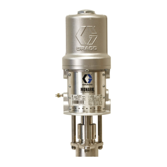
5:1 Ratio Monark Pump
For transfer and supply of solventborne and waterborne finishing materials.
900 psi (6.2 MPa, 62 bar) Maximum Fluid Working Pressure
180 psi (1.2 MPa, 12 bar) Maximum Air Input Pressure
Part No. 218956, Series D
With PTFE Packings
Important Safety Instructions
Read all warnings and instructions in this manual.
Save these instructions.
307044R
II 1/2 G T2
ITS03ATEX11228
Advertisement

Related Manuals for Graco D Series


Summary of Contents for Graco D Series
- Page 1 Instructions–Parts List Divorced Design, 55 Gallon Drum Size, 2” npt Bung Mounting 5:1 Ratio Monark Pump 307044R For transfer and supply of solventborne and waterborne finishing materials. 900 psi (6.2 MPa, 62 bar) Maximum Fluid Working Pressure 180 psi (1.2 MPa, 12 bar) Maximum Air Input Pressure Part No.
- Page 2 D This equipment is for professional use only. D Read all instruction manuals, tags, and labels before operating the equipment. D Use the equipment only for its intended purpose. If you are uncertain about usage, call your Graco distributor. D Do not alter or modify this equipment. Use only genuine Graco parts and accessories.
- Page 3 Permanently coupled hoses cannot be repaired; replace the entire hose. D Use only Graco approved hoses. Do not remove any spring guard that is used to help protect the hose from rupture caused by kinks or bends near the couplings.
- Page 4 WARNING FIRE AND EXPLOSION HAZARD Improper grounding, poor ventilation, open flames or sparks can cause a hazardous condition and result in a fire or explosion and serious injury. D Ground the equipment and the object being sprayed. Refer to Grounding on page 5. D If there is any static sparking or you feel an electric shock while using this equipment, stop spray- ing immediately.
- Page 5 Installation Grounding 6. Fluid supply container: according to your local code. To reduce the risk of static sparking, ground the pump, object being sprayed, and all other spray/dispensing 7. Object being sprayed: according to your local equipment used or located in the spray/dispensing code.
- Page 6 Installation Typical Installation MAIN AIR SUPPLY LINE Bleed–Type Master Air Valve (required, for pump) Fluid Drain Valve (required) Air Line Lubricator Pump Air Regulator Air Line Filter Bleed–Type Master Air Valve (for accessories) Electrically Conductive Air Line Electrically Conductive Fluid Line Pump Runaway Valve Ground Wire (required) 307044...
- Page 7 The Typical Installation shown on page 6 is only a mum) air hose (G) to the pump’s 3/8 npt(f) air inlet. guide for selecting and installing system components and accessories. Contact your Graco distributor for Air Line assistance in designing a system to suit your particular needs.
- Page 8 Operation Pressure Relief Procedure 3. Close the bleed-type master air valve (required in your system). WARNING 4. Unlock the gun/valve trigger safety. 5. Hold a metal part of the gun/valve firmly to the side SKIN INJECTION HAZARD of a grounded metal pail, and trigger the gun/valve Fluid under high pressure can be in- to relieve pressure.
- Page 9 In a circulating system, the pump will run Fill the wet-cup 1/2 full with Graco Throat Seal Liquid continuously and will speed up or slow down as (TSL) or a compatible solvent. Keep the cup half-filled the system demands until the air supply is shut off.
- Page 10 Service section on page 12. Keep the packing nut/wet-cup 1/2 filled with Graco Throat Seal Liquid (TSL) or compatible solvent to help Remove the ball stop pin (17) from the intake valve prolong packing life.
- Page 11 Troubleshooting Before servicing this equipment always make sure to WARNING relieve the pressure. To reduce the risk of serious injury whenever you are instructed to relieve pressure, always follow the Check all possible problems and solutions before Pressure Relief Procedure on page 8. disassembling the pump.
- Page 12 Service Before You Repair the Pump 2. Unscrew the intake valve housing (15). Remove the valve seat (30), pin (17), and ball (5). See Fig. D Be sure you have all the necessary repair parts on hand to reduce down time. 3.
- Page 13 Service DETAIL OF PISTON FOR MEDIUM VISCOSITY 0.19 in. (4.8 mm) †13 8† †13 Lips of packing must face up. Lips of packing must face down. Fig. 4 307044...
- Page 14 Service 11. Remove the cotter pin (2) from the top of the displacement rod (27) and unscrew the rod. Re- move the tie rod nuts (6) and pull the pump hous- ing (36) off the tie rods (24). See Fig. 6. 12.
- Page 15 Service Lips of packing must face up. Lips of packings must face down. 0.020–0.050 in. (0.508–1.27 mm) gap when assembled. Torque to 10–15 ft–lb (14–20 N.m). 22† 23† 19† 21† 20† 13† 8† 13† 30 5 Fig. 6 307044...
- Page 16 Parts Ref. No. 1 includes items 3–5, 8, 10–23, 25–30 and 35–37 †13 †22 8† 23† †13 19† 21† †20 307044...
- Page 17 Parts Model 218956, Series D Part No. Description Qty. Includes items 1–37 20† 164782 O-RING, PTFE 21† 164837 GLAND, male Part No. Description Qty. 22† 165287 BEARING, PTFE 23† 165288 GLAND, female 220465 DISPLACEMENT PUMP 24B189 KIT, tie rod Series D Includes items 3–5, 8, 10–23, 166033 NUT, swivel...
- Page 18 Dimensions Mounting Hole Layout TWO 0.31” (7.9 mm) HOLES ON 5” (127 mm) BOLT CIRCLE 4.38” (111.3 mm) DIA. 3/8 npt(f) AIR INLET 2.5” 2” npt 54.281” (64 mm) 5.0” BUNG (1379 mm) (127 mm) 3/4 npt(f) FLUID OUTLET 42.75” (1086 mm) Technical Data Category...
- Page 19 Notes 307044...
- Page 20 With the exception of any special, extended, or limited warranty published by Graco, Graco will, for a period of twelve months from the date of sale, repair or replace any part of the equipment determined by Graco to be defective.
Need help?
Do you have a question about the D Series and is the answer not in the manual?
Questions and answers