
Related Manuals for J&M 6018


Summary of Contents for J&M 6018
- Page 1 Operator’s Manual MODEL O P E R A T O R ’ S M A N U A L J&M Manufacturing Co, Inc 284 Railroad Street - P.O. Box 547 | Fort Recovery, OH 45846 | Ph: (419) 375-2376 | Fax: (419) 375-2708 www.jm-inc.com...
-
Page 3: Table Of Contents
6018 Specifications ........ -
Page 4: To The Dealer
Use only genuine J&M service parts. Substitute parts may void warranty and may not meet standards required for safety and satisfactory operation. Record the model number and serial number of your equipment in the spaces provided: Model No: 6018 or 6026 NitroGro Applicator Serial No: ________________________ Date of Purchase: ____________ Purchased From: ________________________________________________________________________________ Provide this information to your dealer to obtain correct repair parts. -
Page 5: Serial Number
Serial Number Serial Number______________________ Model Number_______6018 or 6026____ Standard practice when ordering parts or obtaining information from your dealer requires the serial number and model number. Have numbers available before making contact. General Information TO THE OWNER: The purpose of this manual is to assist you in operating and maintaining your applicator in a safe manner. Read it carefully. It furnishes information and instructions that will help you achieve years of dependable performance and help maintain safe operating conditions. -
Page 6: Safety Rules
Safety Rules ATTENTION! BECOME ALERT! YOUR SAFETY IS INVOLVED! Safety is a primary concern in the design and manufacture of our products. Unfortunately, our efforts to provide safe equipment can be erased by an operator’s single careless act. In addition, hazard control and accident prevention are dependent upon the awareness, concern, judgment, and proper training of personnel involved in the operation, transport, maintenance and storage of equipment. -
Page 7: Bolt Torque Chart
Bolt Torque Chart Always tighten hardware to these values unless a different torque or tightening procedure is listed for specific application. Fasteners must always be replaced with the same grade as specified in the manual parts list. Always use the proper tool for tightening hardware. Make sure fastener threads are clean and you start thread engagement properly. -
Page 8: 6018 Specifications
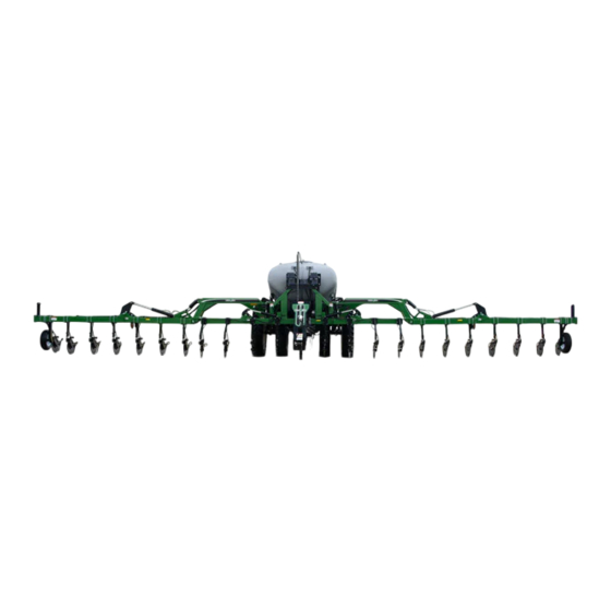
6018 Specifications SPECIFICATIONS 6000 Series Applicators Tank Size 1,850 Gallon Base Width 60’ Ground Clearance 40” Row Spacing* 20”, 22”, 30” Number of Coulters 23, 25, 35, 37 Coulter Style Grove Engineered Products (GEP) or J&M Para-Linkage Fertilizer Delivery Knife or Injection Wing Flex Standard 15°... -
Page 9: 6026 Specifications
6026 Specifications SPECIFICATIONS 6000 Series Applicators Tank Size 2,600 Gallon Base Width 60’ Ground Clearance 40” Row Spacing* 20”, 22”, 30” Number of Coulters 23, 25, 35, 37 Coulter Style Grove Engineered Products (GEP) or J&M Para-Linkage Fertilizer Delivery Knife or Injection Wing Flex Standard 15°... -
Page 10: Pre-Operation Checklist
Pre-Operation Checklist IMPORTANT - Before putting the applicator into operation, check the machine for damaged or worn parts and replace as necessary. Wheel Nuts Tightened During initial operation, tighten standard 3/4” wheel studs and nuts to torque 400 ft-lbs and tighten 1/2”-20 studs and nuts on gauge wheels to torque 80 ft-lbs. - Page 11 Pre-Operation Checklist Defects & Scratches Examine paint and poly tank for scratches, cracks, gouges, and defects. Filling the Tank Warning: Ensure the applicator is pinned to the tractor before filling tank. The applicator must be pinned to a tractor when any fluid is present in the tank.
-
Page 12: Nitrogro Components
NitroGro Components... -
Page 13: Flow Monitors
Flow Monitors Flow monitors allow the operator to check for blockages at each coulter with a floating ball inside the transparent inspection tube. Each coulter is connected with a separate supply hose. Adjusting the Field Depth • Set the center section of coulters first. Spacers are included with the toolbar cylinders. Add or remove spacers until the center section is positioned at the appropriate depth. -
Page 14: Hydraulic Pwm Pump
Hydraulic PWM Pump The standard pump for your NitroGro applicator is the Ace FMC-155-HYD-206 with PWM control. The maximum hydraulic fluid input for this pump is 7 gallons per minute. The optional, larger pump available for your applicator is the Ace FMC-750-HYD pump with PWM control. The maximum hydraulic fluid input pump for this pump is 18 gallons per minute. -
Page 15: Coulter
Coulter The number of coulters is determined by the number of rows (usually one less or one more). So the number of rows will be even, and the number of coulters will be odd, since you are placing the nitrogen between the rows. For example, a 24 row unit will have either 23 or 25 coulters. -
Page 16: Hitching And Unhitching The Applicator
Hitching and Unhitching the Applicator Connect the applicator to the tow vehicle using a hitch pin and make sure a retaining pin is secured in the hitch pin. Always attach the safety chains to the applicator and the tow vehicle. WARNING –... -
Page 17: Folding & Unfolding
Folding & Unfolding Unfolding Folding Toolbar Completely Up Toolbar Completely Up (Down Pressure Circuit - Green Taped Hoses) (Down Pressure Circuit - Green Taped Hoses) Scan to watch Flip Toolbar In the video (Toolbar Flip Circuit - Red Taped Hoses) Main Toolbar Forward and Allow Locks to Fully Engage. - Page 18 Electric Switches Momentary whisker switch for latch/ folding circuit. The height of this switch should be set so that it gets pressed by the parallel arm when the toolbar is completely raised up. It should be plugged into the side of the dual solenoid axle with number 3 and 4 ports (side B).
-
Page 19: Operation
Do not exceed the tire pressure indicated below: 6018 Tires for Single Wheel Applicators VF320/105R46 (Alliance) (172D) VF380/90R46 (Alliance) (173D) 6018 Tires for Walking Tandem Dual Wheel Applicators 6026 Tires for Walking Tandem Dual Wheel Applicators VF320/105R46 (Alliance) (172D) VF320/105R46 (Alliance) (172D) -
Page 20: Raven 450 Controller Set Up
Raven 450 Controller Set Up Initial Console Programming HINT: If you enter the wrong value when entering your data press “ENTER” then press “ENTER” again and re-enter your value again. • Select the unit of measurement by pressing the CE button until the desired selection appears in the display and press “ENTER” NOTE - The unit of measurement for the United States is Volume per Acre. -
Page 21: Raven Isobus Rate Controller Set Up
Raven ISOBUS Rate Controller Set Up • On the second tab from the left, enter the Flowmeter Calibration (Meter Cal) number, approximately 1,340, which is stamped on the flowmeter on the applicator. • Next select Valve Cal. Here, a Self Test speed can be entered for water testing and a nozzle flow check. •... -
Page 22: John Deere Greenstar Rate Controller Pwm Setup
John Deere Greenstar Rate Controller PWM Setup In the System Set-up Tab, select “3-Wire” (C) for the Section Valve Type. See your Nitrogro Owners Manual for information on the number of sections and section widths. In the System Set-up Tab, select “PWM Close” (F) for the Control Valve Type. - Page 23 John Deere Rate Controller 2000 PWM Setup On the Setup Sections page, select “3-Wire” for the Section Valve Type. See “Flow Monitor Set Up” on page 28 for information on the number of sections and section widths. On the Setup Control Valve page, select “PWM Close” for the Control Valve Type. Enter “50”...
-
Page 24: Transporting
Transporting • Comply with ALL state and local laws governing highway safety and regulations when moving machinery on public roads. • Be sure an SMV (Slow Moving Vehicle) emblem is in place and clearly visible on the rear of the applicator. Position the SMV emblem with one point of the triangle upward and as near to the rear and centered or as near to the left of center of the unit as practicable. -
Page 25: Storage
Storage To prolong the life of your NitroGro applicator, hook the applicator to a tractor, unfold it, and perform the following before placing the implement in storage: Pressure wash the NitroGro applicator to remove dirt and debris that may cause rusting. Do NOT use anything Repaint any areas where the paint has been chipped, except RV antifreeze... -
Page 26: Troubleshooting
Troubleshooting WARNING - MAKE SURE THAT ALL POWER IS SHUT OFF BEFORE SERVICING THE APPLICATOR. MAINTENANCE AND REPAIR SERVICE WORK TO BE PERFORMED BY QUALIFIED SERVICEMEN ONLY. Trouble Possible Cause Possible Remedy Outside tool bar wing creeps Counterbalance valve is too loose Tighten counterbalance valve. -
Page 27: Adapter Harnesses For Various Controller Options
Troubleshooting HIGH BACK PRESSURE IN THE RETURN LINE: This is the most common cause of shortened motor seal life. the hydraulic motor seal is rated for 250 psi of back pressure. However, a continuous return pressure of 100 psi or less is recommended for efficient operation and optimum seal life. The high return pressure is caused by restrictions in hoses, fittings, and tractor plumbing. -
Page 28: Flow Monitor Set Up
Flow Monitor Set Up The NitroGro applicator offers row spacing options of 20”, 22”, or 30”. The unit will either be set up to or re-apply the outside row (“1 Up”), or skip a row (“1 Down”). Using your row spacing and whether your applicator is “1 Up” or “1 Down”, refer to the chart below to determine the location and quantity of flow monitors for your applicator. -
Page 29: Changing From 60' To 40' Wing Span
Changing from 60’ to 40’ Wing Span Changing from 60’ to 40’ • Unfold your applicator as normal. Rotate the wings forward and engage the latches. • Unfold the outer wings and stub wings enough to place the cylinder stops on the wings. •... -
Page 30: Injectors - 20" Row Spacing
Injectors - 20” Row Spacing 20 Gallons Per Acre 25 Gallons Per Acre Speed (MPH) #10 Injector (psi) #15 Injector (psi) #20 Injector (psi) #30 Injector (psi) #40 Injector (psi) GPM (per nozzle) 0.34 0.43 0.52 0.60 0.69 0.77 0.86 0.95 1.03 0.43 0.54 0.64 0.75 0.86 0.97 1.07 1.18 1.29 Flow Indicator 1/2"... - Page 31 Injectors - 20” Row Spacing 50 Gallons Per Acre 55 Gallons Per Acre Speed (MPH) #10 Injector (psi) 103 115 104 115 129 #15 Injector (psi) #20 Injector (psi) #30 Injector (psi) #40 Injector (psi) GPM (per nozzle) 0.86 1.07 1.29 1.50 1.72 1.93 2.15 2.36 2.58 0.95 1.18 1.42 1.66 1.89 2.13 2.36 2.60 2.84 Flow Indicator 1/2"...
-
Page 32: Injectors - 22" Row Spacing
Injectors - 22” Row Spacing 15 Gallons Per Acre Speed (MPH) #10 Injector (psi) #15 Injector (psi) #20 Injector (psi) #30 Injector (psi) #40 Injector (psi) GPM (per nozzle) 0.25 0.31 0.38 0.44 0.50 0.57 0.63 0.69 0.75 Flow Indicator Red Glass Ball Level 1.1 1.7 Flow Indicator 1/2"... - Page 33 Injectors - 22” Row Spacing 40 Gallons Per Acre 45 Gallons Per Acre Speed (MPH) #10 Injector (psi) 102 114 #15 Injector (psi) #20 Injector (psi) #30 Injector (psi) #40 Injector (psi) GPM (per nozzle) 0.76 0.95 1.14 1.32 1.51 1.70 1.89 2.08 2.27 0.85 1.06 1.28 1.49 1.70 1.92 2.13 2.34 2.55 Flow Indicator 1/2"...
-
Page 34: Injectors - 30" Row Spacing
Injectors - 30” Row Spacing 15 Gallons Per Acre Speed (MPH) #10 Injector (psi) #15 Injector (psi) #20 Injector (psi) #30 Injector (psi) #40 Injector (psi) GPM (per nozzle) 0.34 0.43 0.51 0.60 0.68 0.77 0.86 0.94 1.03 Flow Indicator Red Glass Ball Level Flow Indicator 1/2"... - Page 35 Injectors - 30” Row Spacing 40 Gallons Per Acre 45 Gallons Per Acre Speed (MPH) #10 Injector (psi) 115 128 143 113 132 146 163 #15 Injector (psi) #20 Injector (psi) #30 Injector (psi) #40 Injector (psi) GPM (per nozzle) 1.03 1.29 1.55 1.81 2.06 2.32 2.58 2.84 3.10 1.16 1.45 1.74 2.03 2.32 2.61 2.90 3.19 3.48 Flow Indicator 1/2"...
-
Page 36: Knife - 20" Row Spacing
Knife - 20” Row Spacing 10 Gallons Per Acre 15 Gallons Per Acre Speed (MPH) 0.075 Orifice Pressure (psi) 0.107 Orifice Pressure (psi) 0.132 Orifice Pressure (psi) 0.161 Orifice Pressure (psi) GPM (per nozzle) 0.15 0.19 0.23 0.27 0.30 0.34 0.38 0.42 0.46 0.23 0.29 0.34 0.40 0.46 0.51 0.57 0.63 0.68 Flow Indicator Red Glass Ball Level Flow Indicator 1/2"... - Page 37 Knife - 20” Row Spacing 40 Gallons Per Acre 45 Gallons Per Acre Speed (MPH) 0.075 Orifice Pressure (psi) 103 117 131 145 103 119 134 150 165 0.107 Orifice Pressure (psi) 0.132 Orifice Pressure (psi) 0.161 Orifice Pressure (psi) GPM (per nozzle) 0.61 0.76 0.91 1.07 1.22 1.37 1.52 1.67 1.83 0.68 0.86 1.03 1.20 1.37 1.54 1.71 1.88 2.05 Flow Indicator 1/2"...
-
Page 38: Knife - 22" Row Spacing
Knife - 22” Row Spacing 10 Gallons Per Acre 15 Gallons Per Acre Speed (MPH) 0.075 Orifice Pressure (psi) 0.107 Orifice Pressure (psi) 0.132 Orifice Pressure (psi) 0.161 Orifice Pressure (psi) GPM (per nozzle) 0.17 0.21 0.25 0.29 0.33 0.38 0.42 0.46 0.50 0.25 0.31 0.38 0.44 0.50 0.57 0.63 0.69 0.75 Flow Indicator Red Glass Ball Level Flow Indicator 1/2"... - Page 39 Knife - 22” Row Spacing 40 Gallons Per Acre 45 Gallons Per Acre Speed (MPH) 0.075 Orifice Pressure (psi) 100 116 131 146 161 116 133 150 167 184 0.107 Orifice Pressure (psi) 0.132 Orifice Pressure (psi) 0.161 Orifice Pressure (psi) GPM (per nozzle) 0.67 0.84 1.00 1.17 1.34 1.51 1.67 1.84 2.01 0.75 0.94 1.13 1.32 1.51 1.70 1.88 2.07 2.26 Flow Indicator 1/2"...
-
Page 40: Knife - 30" Row Spacing
Knife - 30” Row Spacing 10 Gallons Per Acre 15 Gallons Per Acre Speed (MPH) 0.075 Orifice Pressure (psi) 0.107 Orifice Pressure (psi) 0.132 Orifice Pressure (psi) 0.161 Orifice Pressure (psi) GPM (per nozzle) 0.23 0.29 0.34 0.40 0.46 0.51 0.57 0.63 0.68 0.34 0.43 0.51 0.60 0.68 0.77 0.86 0.94 1.03 Flow Indicator Red Glass Ball Level 0.9 Flow Indicator 1/2"... - Page 41 Knife - 30” Row Spacing 40 Gallons Per Acre 45 Gallons Per Acre Speed (MPH) 0.075 Orifice Pressure (psi) 103 124 145 165 186 207 228 119 142 165 189 212 235 259 0.107 Orifice Pressure (psi) 102 114 0.132 Orifice Pressure (psi) 0.161 Orifice Pressure (psi) GPM (per nozzle) 0.91 1.14 1.37 1.60 1.83 2.05 2.28 2.51 2.74 1.03 1.28 1.54 1.80 2.05 2.31 2.57 2.83 3.08...
Need help?
Do you have a question about the 6018 and is the answer not in the manual?
Questions and answers