Table of Contents
Advertisement
Quick Links
Advertisement
Table of Contents

Related Manuals for Isenberg 230.4201


Summary of Contents for Isenberg 230.4201
- Page 1 Installation Manual - 230.4201 3/4” Thermostatic Valve & Trim BEFORE YOU BEGIN • You must observe all local plumbing laws and codes. • Do not install this valve if it does not meet local plumbing codes. • Shut off the main water supply. Ver. 2.54 www.isenbergfaucets.com...
-
Page 2: Table Of Contents
TABLE OF CONTENTS • Operating Specifications . . . . . . . 1 • Valve Installation And Tolerance • Cut-Out Dimensions . . . . . . . • Rough In Specification . . . . . . • Connecting The Supply & Output Lines . . . . . ... -
Page 3: Operating Specifications
ONLY! If water pressure is greater than 80 PSI install a pressure reducing valve (PRV) This valve meets or exceeds ANSI A112.18.1 and ASSE 1016 This valve is certified by IAPMO CUT OUT DIMENSIONS Isenbergʼs TVH Series valves comes with a black pre-attached mud-guard. This mud-guard is not to be removed or discarded. Its purpose is to guide the installation professional on the proper cut-out dimensions of the drywall. Wall Cut Out Dimensions From Center Point of Valve: TVH.4201 X = 68mm / 2.67” Y = 113mm / 4.44” www.isenbergfaucets.com... -
Page 4: Rough In Specification
ROUGH IN SPECIFICATION Maximum = 87.5mm [3,44"] Minimum = 70.5mm [2,77"] The distance between back of the valve to the nished tile surface should be between 2.77” and 3.44” inches. Finished tile should fall between Min & Max. If valve is installed too deep into the wall, extensions are available. -
Page 5: Connecting The Supply & Output Lines
CONNECTING THE SUPPLY & OUTPUT LINES Fix Valve on wooden plank Level Valve Attach Hot/Cold Lines Attach Output Lines www.isenbergfaucets.com... -
Page 6: Trim Markings / Water Output
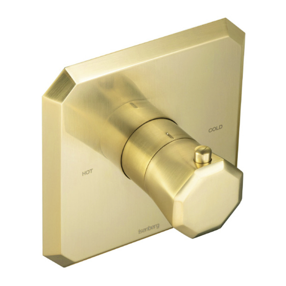
FINISH TILE POSITION Install Drywall and Tile. Ensure finished tile surface is between the min and max marks on the mud guards. TRIM MARKINGS / WATER OUTPUT The below diagram shows the markings on the trim plate and the outputs on the valve. This will help the installation professional to connect the appropriate accessories to the valve output ports Note: The TVH.4201 valve does not have volume control capability. It must be used with a volume control valve such as the TVH.4511 or a diverter valve such as the TVH.4371 www.isenbergfaucets.com... -
Page 7: Using The Supply Stops
USING THE SUPPLY STOPS Turn Clock-wise 7 times to stop water flow. FLUSHING THE VALVE In order to clear dirt in the lines - you must flush the valve before the wall is closed and water is turned on for the first time. 1) Remove the 2 supply stops by turning with a spanner 2) Remove thermostatic cartridge by turning with a spanner 3) Turn on water supply and let water flow removing any dirt in the lines. www.isenbergfaucets.com... -
Page 8: Installing The Trim
INSTALLING THE TRIM - TRIM PLATE SIZE AND SHAPE MAY VARY - ILLUSTRATION ONLY Remove mud guard Install 42mm ring The 42mm ring must be flush. Otherwise the handle A hard push may be required will not fit properly www.isenbergfaucets.com... - Page 9 INSTALLING THE TRIM - TRIM PLATE SIZE AND SHAPE MAY VARY - ILLUSTRATION ONLY Insert trim plate Align Trim plate till it is straight Caliberate cartridge before inserting temperature Remove anti-scald temperature ring handle. Red marks must align. www.isenbergfaucets.com...
- Page 10 INSTALLING THE TRIM - TRIM PLATE SIZE AND SHAPE MAY VARY - ILLUSTRATION ONLY Correctly re-insert anti-scald temperature ring in the right position The button on the temperature handle is an anti This photo shows a completely installed trim scald feature. In order to rotate the handle further to “HOT” the button must be pressed www.isenbergfaucets.com...
-
Page 11: Replacing The Thermostatic Cartridge
REPLACING THE THERMOSTATIC CARTRIDGE 1. Remove Anti-Scald Ring 2. The temperature cartridge can be removed easily in one operation by using a spanner. Use a spanner to twist in the shown position and remove supply stop REPLACING THE SUPPLY STOPS www.isenbergfaucets.com... -
Page 12: Installing The Extension Kit
INSTALLING EXTENSIONS TO THE VALVE - OPTIONAL Remove anti scald temperature ring Install temperature extension piece as shown above. Tighten Screw Reinsert anti scald temperature ring www.isenbergfaucets.com... -
Page 13: Cartridge Maintenance
CARTRIDGE CLEANING & MAINTENANCE CARTRIDGE CLEANING & MAINTENANCE Thermostatic Cartridge: Clean Filters Check For Dirt Inspect O-rings www.isenbergfaucets.com...
Need help?
Do you have a question about the 230.4201 and is the answer not in the manual?
Questions and answers