Table of Contents
Advertisement
Quick Links
Installation Manual - PBV.1005A
1/2" Pressure Balance Valve With Integrated 2-way Diverter
Ver. 2.53
www.isenbergfaucets.com
Use With Trims Ending in *2101 & *2100
BEFORE YOU BEGIN
•
You must observe all local plumbing laws and codes.
•
Do not install this valve if it does not meet local plumbing codes.
•
Shut off the main water supply.
Advertisement
Table of Contents

Related Manuals for Isenberg PBV.1005A


Summary of Contents for Isenberg PBV.1005A
- Page 1 Installation Manual - PBV.1005A 1/2” Pressure Balance Valve With Integrated 2-way Diverter Use With Trims Ending in *2101 & *2100 BEFORE YOU BEGIN • You must observe all local plumbing laws and codes. • Do not install this valve if it does not meet local plumbing codes. • Shut off the main water supply. Ver. 2.53 www.isenbergfaucets.com...
-
Page 2: Table Of Contents
TABLE OF CONTENTS • Operating Specifications . . . . . . . 1 • Valve Installation And Tolerance • Cut-Out Dimensions . . . . . . . • Rough In Specification . . . . . . • Connecting The Supply & Output Lines . . . . . ... -
Page 3: Operating Specifications
ONLY! If water pressure is greater than 80 PSI install a pressure reducing valve (PRV) This valve meets or exceeds ANSI A112.18.1 and ASSE 1016 This valve is certified by IAPMO CUT OUT DIMENSIONS Isenbergʼs PBV1005A valve comes with a pre-at- tached mud-guard. This mud-guard is not to be removed or discarded. Its purpose is to guide the installation professional on the proper cut-out dimensions of the drywall. Wall Cut Out Dimensions From Center Point of Valve: PBV.1005A X = 138mm / 5.43” Y = 121mm / 4.76” www.isenbergfaucets.com... -
Page 4: Rough In Specification
ROUGH IN SPECIFICATION Maximum = 80mm [3,14"] Minimum = 62mm [2,44"] The distance between back of the valve to the nished tile surface should be between 2.44 and 3.14 inches. Finished tile should fall between Min & Max. If valve is installed too deep into the wall, extensions are available. -
Page 5: Connecting The Supply & Output Lines
CONNECTING THE SUPPLY & OUTPUT LINES Fix Valve on wooden plank Level Valve Attach Hot/Cold Supply Lines www.isenbergfaucets.com... - Page 6 CONNECTING THE SUPPLY & OUTPUT LINES Level Valve Attach Hot/Cold Supply Lines www.isenbergfaucets.com...
-
Page 7: Trim Markings / Water Output
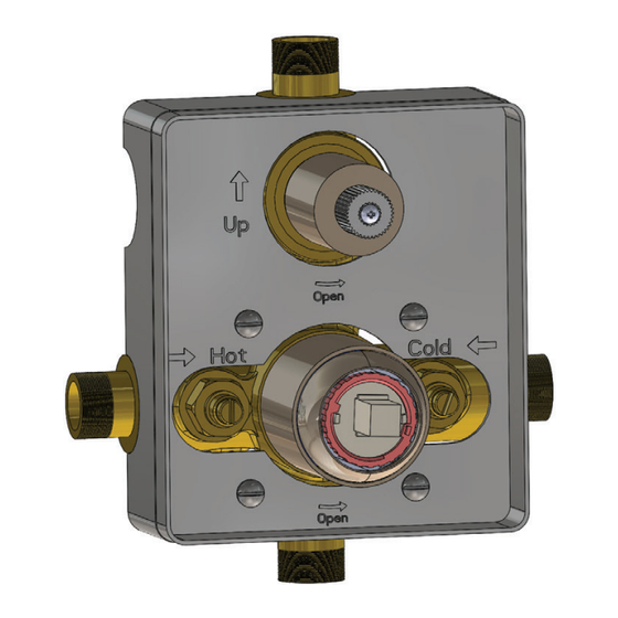
FINISH TILE POSITION Install Drywall and Tile. Ensure finished tile surface is between the min and max marks on the mud guards. TRIM MARKINGS / WATER OUTPUT The below diagram shows the markings on the trim plate and the outputs on the valve. This will help the installation professional to connect the appropriate accessories to the valve output ports OUTPUT 2 COLD OUTPUT 1 www.isenbergfaucets.com... -
Page 8: Using The Supply Stops
USING THE SUPPLY STOPS Turn Clock-wise 7 times to stop water flow. FLUSHING THE VALVE In order to clear dirt in the lines - you must flush the valve before the wall is closed and water is turned on for the first time. 1) Remove the 2 supply stops by turning with a spanner 2) Remove temperature cartridge by turning with a spanner 3) Remove volume control cartridge by turning with a spanner 4) Turn on water supply and let water flow removing any dirt in the lines. www.isenbergfaucets.com... - Page 9 INSTALLING THE TRIM - TRIM PLATE SIZE AND SHAPE MAY VARY - ILLUSTRATION ONLY Remove mud guards Apply silicone between mud guard and dry wall / tile Apply silicone behind trim plate Push trim plate towards wall www.isenbergfaucets.com...
- Page 10 INSTALLING THE TRIM - TRIM PLATE SIZE AND SHAPE MAY VARY - ILLUSTRATION ONLY Insert diverter handle Insert temperature handle and tighten hex screw, then insert cover button This photo shows a completely installed trim www.isenbergfaucets.com...
-
Page 11: Replacing The Temperature Cartridge
REPLACING THE DIVERTER CARTRIDGE 1. Remove diverter cover by turning with hand 2. Removed diverter holding nut with wrench 3. Remove diverter cartridge REPLACING THE TEMPERATURE CARTRIDGE 1. Remove cartridge circular bezel with hand 2. Removed cartridge retaining nut with wrench 3. Remove temperature cartridge www.isenbergfaucets.com... -
Page 12: Installing The Extension Kit
INSTALLING EXTENSIONS TO THE VALVE - OPTIONAL Remove diverter trim piece Insert Diverter extension Remove temperature cartridge and cartridge cover Insert temperature extension piece and extended cartridge cover www.isenbergfaucets.com... - Page 13 INSTALLING EXTENSIONS TO THE VALVE - OPTIONAL Insert temperature cartridge, retaining nut and Fully installed extension kit is seen above bezel www.isenbergfaucets.com...
Need help?
Do you have a question about the PBV.1005A and is the answer not in the manual?
Questions and answers