Table of Contents
Advertisement
Quick Links
Advertisement
Table of Contents

Related Manuals for Isenberg 160.1800


Summary of Contents for Isenberg 160.1800
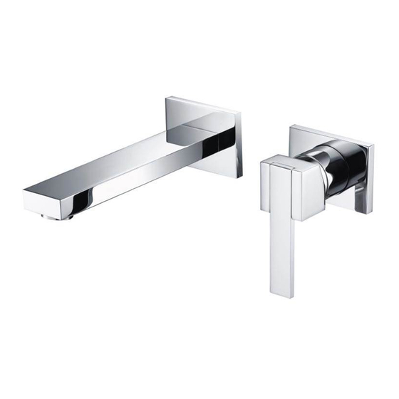
- Page 1 Installation Manual 160.1800 150.1800 260.1800 Wall Mount Lavatory Faucet - Single Lever BEFORE YOU BEGIN • You must observe all local plumbing laws and codes. • Do not install this valve if it does not meet local plumbing codes. • Shut off the main water supply. Ver. 2.54 www.isenbergfaucets.com...
-
Page 2: Table Of Contents
TABLE OF CONTENTS • Operating Specifications . . . . . . . 1 • Valve Installation And Tolerance • Cut-Out Dimensions . . . . . . . • Rough In Specification . . . . . . • Connecting The Supply & Output Lines . . . . . ... -
Page 3: Operating Specifications
OPERATING SPECIFICATIONS WATER TEMPERATURE WATER PRESSURE This product is to be used with water at This product is to be used with a water pressure range of 15 PSI to 80 PSI ONLY a temperature range of 40˚F - 120˚F ONLY! If water pressure is greater than 80 PSI install a pressure reducing valve (PRV) This valve meets or exceeds ANSI A112.18.1 and ASSE 1016 This valve is certified by IAPMO CUT OUT DIMENSIONS Wall Cut Out Dimensions: Left Hole ø = 1.12” [28.5 mm] Right Hole ø = 1.96“ [50.0 mm] Distance Between Holes X - 4.92”... -
Page 4: Rough In Specification
ROUGH IN SPECIFICATION Maximum = 38,5mm [1,51"] The distance between back of the valve to the nished tile Minimum = surface should be between 61,5mm [2,42"] 1.51” and 2.42” inches. Finished tile should fall between Min & Max. If valve is installed too deep into the wall, extensions are available. -
Page 5: Connecting The Supply & Output Lines
CONNECTING THE SUPPLY & OUTPUT LINES Fix Valve on wooden plank Level Valve Attach Hot/Cold Lines www.isenbergfaucets.com... -
Page 6: Replacing Cartridge
REPLACING THE CARTRIDGE FLUSHING THE VALVE In order to clear dirt in the lines - you must flush the valve before the wall is closed and water is turned on for the first time. 1) Remove the cartridge 2) Remove the output connector 3) Turn on water supply and let water flow removing any dirt in the lines. www.isenbergfaucets.com... -
Page 7: Installing The Trim
INSTALLING THE TRIM - SIZE AND SHAPE MAY VARY - ILLUSTRATION ONLY Remove mud guards Insert Cartridge Flange Insert Spout Insert handle and tighten hex screw. Insert cover button www.isenbergfaucets.com... - Page 8 INSTALLING THE TRIM - SIZE AND SHAPE MAY VARY - ILLUSTRATION ONLY Tighten hex screws under spout Fully installed trim www.isenbergfaucets.com...
-
Page 9: Installing Extensions
INSTALLING EXTENSIONS TO THE VALVE - OPTIONAL Remove existing parts as seen above Insert cartridge extension and guide pins Ensure 3 o-rings are placed in the above seen Insert extended cartridge cover position - use grease if necessary www.isenbergfaucets.com... - Page 10 INSTALLING EXTENSIONS TO THE VALVE - OPTIONAL Insert cartridge and tighten Insert extended spout piece Fully installed extension is seen above www.isenbergfaucets.com...
-
Page 11: Cartridge Maintenance
CARTRIDGE CLEANING & MAINTENANCE Check For Dirt Inspect Rubber Seal Check For Dirt www.isenbergfaucets.com 9...
Need help?
Do you have a question about the 160.1800 and is the answer not in the manual?
Questions and answers