Table of Contents
Advertisement
Quick Links
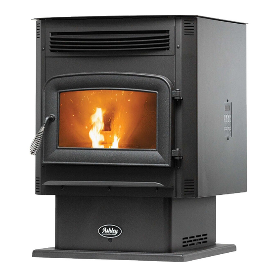
Owner's Instruction and Operation Manual
Model Number:
AP5617-W
Report #: F22-777
Certified to ASTM E1509-2022 and Certified to
CAN/ULC S627:2023; Complies to CAN ICES-
3(B)/NMB-3(B); Contains IC:23243-WBR1DIPEX
Mobile Home / Transportable Building
Approved
* All Pictures In This Manual Are For Illustrative Purposes Only. Actual Product May Vary.
Save These Instructions In A Safe Place For Future Reference.
SAFETY NOTICE: If this heater is not properly installed, a house fire may result.
For your safety, follow the installation instructions. Never use make-shift
compromises during the installation of this heater. Contact local building or
fire officials about permits, restrictions and installation requirements in your
area. NEVER OPERATE THIS PRODUCT WHILE UNATTENDED.
CAUTION! Please read this entire manual before you install or use your new room
heater. Failure to follow instructions may result in property damage, bodily injury,
or even death. Improper Installation Will Void Your Warranty!
U.S. Environmental Protection Agency
Certified to comply with 2020 particulate
emissions standards.
THIS MANUAL IS SUBJECT TO CHANGE WITHOUT NOTICE.
© 2023 United States Stove Company, 227 Industrial Park Rd., South Pittsburg, TN 37380
R
CALIFORNIA PROPOSITION 65 WARNING:
This product can expose you to chemicals including carbon
monoxide, which is known to the State of California to cause
cancer, birth defects, and/or other reproductive harm. For
more information, go to
853997-0804M
www.P65warnings.ca.gov
Ph. 800-750-2723
Advertisement
Table of Contents

Related Manuals for Ashley AP5617-W


Summary of Contents for Ashley AP5617-W
- Page 1 Owner’s Instruction and Operation Manual Model Number: AP5617-W Report #: F22-777 Certified to ASTM E1509-2022 and Certified to CAN/ULC S627:2023; Complies to CAN ICES- 3(B)/NMB-3(B); Contains IC:23243-WBR1DIPEX Mobile Home / Transportable Building Approved * All Pictures In This Manual Are For Illustrative Purposes Only. Actual Product May Vary.
- Page 2 / transportable building. Your stove is Certified to ASTM E1509-2022 and Certified to CAN/ULC S627:2023. This manual describes the installation and operation of the Ashley, AP5617-W pellet stove. This heater meets the 2020 U.S. Environmental Protection Agency’s crib wood emission limits for wood-heaters sold after May 15, 2020.
-
Page 3: Installation Checklist
INSTALLATION CHECKLIST Your Wood Stove should be installed by a qualified installer only. An NFI qualified Installer can be found at www.nficertified.org/public/find-an-nfi-pro/ CUSTOMER SERVICE 1-800-750-2723 ext 5050 Text to 423-301-5624 Email to: Customerservice@usstove.com COMMISSIONING CHECKLIST This checklist is to be completed in full by the qualified person who installs this unit. Keep this page for future reference. - Page 4 ASSEMBLY INSTRUCTIONS FOR CUSTOMER SERVICE CALL: 800-750-2723 EXT 5050 Pull the factory installed 5 Pin Main Wiring 4. Secure the control panel to the top of the stove Harness and 7 Pin Com Cabel out of the top of with two sheet metal screws. the stove.
-
Page 5: Installation
INSTALLATION FOR CUSTOMER SERVICE CALL: 800-750-2723 EXT 5050 SAFETY NOTICE CAUTION: • IF THIS STOVE IS NOT PROPERLY INSTALLED, BURNING FUEL CREATES CARBON MONOXIDE A HOUSE FIRE MAY RESULT. TO REDUCE THE AND CAN BE HAZARDOUS TO YOUR HEALTH RISK OF FIRE, FOLLOW THE INSTALLATION IF NOT PROPERLY VENTED. -
Page 6: Installation Options
INSTALLATION INSTALLATION OPTIONS CLEARANCES Freestanding Unit - supported by pedestal/legs Your pellet stove has been tested and listed and placed on a non-combustible floor surface for installation in residential, mobile home / in compliance with clearance requirements for a transportable building in accordance with the freestanding stove installation. -
Page 7: Venting Requirements
INSTALLATION • Vent must be 3 or 4-inch “PL” Vent and must ATTENTION: extend a minimum or 36” (914 mm) above the roof DO NOT VENT UNDER ANY PORCH, DECK, line of the mobile home / transportable building AWNING, OR IN ANY SEMI ENCLOSED OR and must be installed using a certified ceiling fire ROOFED AREA. -
Page 8: Pellet Vent Termination
INSTALLATION or shrubs to high temperatures. The maximum at least 3 screws, and all joints must be sealed with recommend vertical venting height is 12-feet for Hi-Temp RTV silicone sealant to be airtight. The 3-inch type “PL” vent. Total length of horizontal area where the vent pipe penetrates to the exterior vent must not exceed 4-feet. - Page 9 INSTALLATION D. Minimum 7-foot (2.13m) clearance from any This appliance is certified for use with listed 3 inch grade when adjacent to public walkways. or 4 inch “PL” pellet venting products. The use of other components other than stated herein could E.
-
Page 10: Through The Wall Installation
INSTALLATION annular space of the wall thimble and around would complete the installation. A support bracket the vent pipe with high temperature silicone should be placed just below the termination cap sealant. or one every 4ft (1.22m) to make the system more stable. - Page 11 INSTALLATION VENTING YOUR PELLET STOVE INTO AN EXISTING CLASS A 6” CHIMNEY SYSTEM IMPORTANT: Existing Class ‘A’ 6” Chimney System IF YOU ARE INSTALLING YOUR PELLET STOVE AS A REPLACEMENT TO AN EXISTING WOOD STOVE, YOU CAN INSTALL YOUR PELLET STOVE USING THE EXISTING CLASS A 6”...
-
Page 12: Control Panel Overview
OPERATION INSTRUCTIONS NEVER OPERATE THIS PRODUCT WHILE UNATTENDED HOW YOUR HEATER WORKS • Pressing the “OFF” button on the control panel will cause the heater to enter its shut-down Your pellet heater operates on a timer based auger sequence. The fuel feed system will stop pulling fuel feed system, that is controlled by a digital circuit fuel from the hopper and, once the fire goes out board. -
Page 13: Proper Fuel
OPERATION INSTRUCTIONS Your pellet stove is designed to burn premium WARNING: hardwood pellets that comply with the Pellet Fuels • DO NOT USE CHEMICALS OR FLUIDS TO Institute (PFI) standard (minimum of 40 lbs density START THE FIRE - NEVER USE GASOLINE, per cubic ft, 1/4”... - Page 14 OPERATION INSTRUCTIONS is in operation it must be closed within 30 seconds, CAUTION: or the stove will shut down. If the stove shuts down • KEEP FOREIGN OBJECTS OUT OF THE push the “On/Off” button to re-start your stove. The HOPPER.
-
Page 15: Shutdown Procedure
OPERATION INSTRUCTIONS or longer depending on the heat remaining in Your stove is equipped with a high temperature the appliance. After the stove components stop thermodisc. This unit has a manual reset running all lights on the display will go out and the thermodisc. -
Page 16: Maintenance
OPERATION INSTRUCTIONS b. Use the tab located at the top of the center d. Remove fly ash. panel to lift the panel up and out of the unit. It is possible that creosote may accumulate in the exhaust fan therefore, this must be brushed clean. The exhaust fan can be found behind the left side panel (facing the front of the heater), the circulation fan can be found behind the right side panel. -
Page 17: Blower Motors
MAINTENANCE occurred. If creosote has accumulated, it should gas when exposed to elevated concentrations be removed to reduce the risk of a chimney fire. for extended periods of time. While the modern Inspect the system at the stove connection and combustion systems in heaters drastically reduce at the chimney top. -
Page 18: Fall Start Up
MAINTENANCE Once the heater has cooled, remove the door button with the viewing door open). Vacuum out from the heater. the hopper. Thoroughly clean the burn pot, and firebox. It may be desirable to spray the inside of 2. Remove the rope gasket from the door followed the cleaned hopper with an aerosol silicone spray by the nuts holding the glass retainer in place. -
Page 19: How To Order Repair Parts
HOW TO ORDER REPAIR PARTS For Parts Assistance Call: 800-750-2723 Ext 5051 or Email: parts@usstove.com The information in this owner’s manual is specific to your unit. When ordering replacement parts the information in this manual will help to ensure the correct items are ordered. Before contacting customer service write down the model number and the serial number of this unit. -
Page 20: Troubleshooting Guide
TROUBLESHOOTING GUIDE When your stove acts out of the ordinary, the first reaction is to call for help. This guide may save time and money by enabling you to solve simple problems yourself. Problems encountered are often the result of only five factors: 1) poor fuel;... - Page 21 TROUBLESHOOTING GUIDE Display is Flashing “E2” Possible Causes Possible Remedies: (Unplug stove first when possible) Unhook air hose from the air switch and blow through it. Airflow switch hose or stove attachment If air flows freely, the hose and tube are fine. If air will not pipes for hose are blocked.
- Page 22 TROUBLESHOOTING GUIDE Display is Flashing “E3” Possible Causes Possible Remedies: (Unplug stove first when possible) The hopper is out of pellets Refill the hopper. The air dampener is too far open for a low If on the low setting, you may need to close the dampener feed setting all the way.
- Page 23 TROUBLESHOOTING GUIDE Display is Flashing “E4” Possible Causes Possible Remedies: (Unplug stove first when possible) The air inlet, burnpot, interior combustion chambers, combustion blower, Follow all cleaning procedures in the maintenance section exhaust pipe are blocked with ash or foreign of the owner’s manual.
- Page 24 TROUBLESHOOTING GUIDE Stove Feeds Pellets, But Will Not Ignite Possible Causes Possible Remedies: (Unplug stove first when possible) In some situations it may be necessary to have the damper completely closed for ignition to take place. After there is Air damper open too far for ignition. a flame, the damper can then be adjusted for the desired feed setting.
-
Page 25: Repair Parts
REPAIR PARTS Part # Description Part # Description 893241-AW Door Handle Shaft Kit RTD Temperature 80915 Probe 88324 1” Rope Gasket 5 ft 80869 Ceramic Ignitor 88174 Flat Glass Gasket 4 ft 88118 Ignitor Flange Gasket 893159 Clear Glass 80549 Pressure Switch 893939 Glass Retainer Kit... -
Page 26: Wiring Diagram
WIRING DIAGRAM ... -
Page 27: Service Record
SERVICE RECORD It is recommended that your heating system is serviced regularly and that the appropriate Service Interval Record is completed. SERVICE PROVIDER Before completing the appropriate Service Record below, please ensure you have carried out the service as described in the manufacturer’s instructions. Always use the manufacturer's specified spare part when replacement is necessary. - Page 28 NOTES © 2023 United States Stove Company...
- Page 29 NOTES © 2023 United States Stove Company...
Need help?
Do you have a question about the AP5617-W and is the answer not in the manual?
Questions and answers