Table of Contents
Advertisement
READ THIS ENTIRE MANUAL, THOROUGHLY, BEFORE ATTEMPTING TO INSTALL AND/
OR BURN YOUR NEW ASHLEY *MULTI-FUEL HEATER. FAILURE TO FOLLOW THESE IN-
STRUCTIONS MAY RESULT IN PROPERTY DAMAGE, BODILY INJURIES OR EVEN
DEATH.
Safety Notice: If this heater is not properly installed, a house fire may result.
For your safety, follow the installation directions. Contact local building or fire of-
ficials about restrictions and installation requirements peculiar to your area. Do
S S
C C
Not Plug this appliance into an electrical outlet before reading and understanding
U U
S S
all operations and always unplug the unit before attempting any work or main-
tenance. Do not connect this heater to any chimney flue already serving another
appliance. Carefully observe and maintain all clearances to combustibles.
A note about fuel: Use only dried shelled corn with a moisture content of 14%
or less (11 to 12% provides the best results); any pellet fuel used should
have an ash content of 1% or less. If not, efficiency will suffer. This heater has
successfully burned pellets with a 2-1/2% ash content, though less ash is preferred
and more efficient.
Your Ashley Multi-Fuel Heater operates on a negative pressure. Therefore, all
venting connections (elbows, T-pipe) must be sealed and airtight.
i Use Hi-Temp silicone at each joint or connection.
*This heater is capable of burning wood, biomass pellets and a wide variety of grains,
including corn, soybeans, cherry and olive pits, and all larger seeds.
SAVE THESE INSTRUCTIONS
UNITED STATES STOVE COMPANY GRANTS NO WARRANTY, IMPLIED OR STATED,
FOR THE INSTALLATION OR MAINTENANCE OF THE HEATER AND ASSUMES NO
RESPONSIBILITY FOR ANY CONSEQUENTIAL DAMAGE(S).
Tested &
Portland
Listed By
Oregon USA
US
Omni-Test Laboratories, Inc.
Safety Tested to ASTM-E 1509, (UM) 84-HUD
United States Stove Company • 227 Industrial Park Road, P.O. Box 151 • South Pittsburg, TN 37380 • www.usstove.com
851832
USSC
1
Advertisement
Table of Contents

Related Manuals for Ashley APC1406


Summary of Contents for Ashley APC1406
- Page 1 READ THIS ENTIRE MANUAL, THOROUGHLY, BEFORE ATTEMPTING TO INSTALL AND/ OR BURN YOUR NEW ASHLEY *MULTI-FUEL HEATER. FAILURE TO FOLLOW THESE IN- STRUCTIONS MAY RESULT IN PROPERTY DAMAGE, BODILY INJURIES OR EVEN DEATH. Safety Notice: If this heater is not properly installed, a house fire may result.
-
Page 2: Specifications
Heating Capacity 1,000-2,000 Sq. Ft Fuel Storage Capacity 60 Lbs. Width 29 in./737mm APC1406 APCI1406 Height 31 in./787mm 24 in./610mm Depth 28 in./711mm BTU output will vary, depending on the brand, type and quality of fuel and the moisture content. Consult your ... - Page 3 APC1406 ASSEMBLY Assembly 1. Unpack unit and make sure all components are included; (4) Legs, and all hardware for installation. 2. Fold the corner padding from the carton and lay it on the floor behind the unit. This is used to hold the heater up off the floor to install the legs.
- Page 4 APCI1406 ASSEMBLY DISCONNECT THE POWER CORD BEFORE SERVICING THIS Heater For the following assemblies, we suggest locating the unit near it’s desired location. Depending on installation, you may want to connect the exhaust venting before installing the facade parts. Assembly - Facade (Surround) Remove contents from packaging and make sure you have all components: (2) Top Facade (a)
-
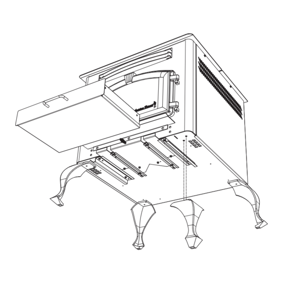
Page 5: Component Location
COMPONENT LOCATION USSC... -
Page 6: Safety Steps
Contact your local building inspector to obtain any necessary permits or inspection guidelines before installing the product. The ASHLEY heater is designed to burn dry shelled corn, cherry pits, or pelletized fuel such as wood and •... -
Page 7: Shelled Corn
Only wood pellets manufactured to the Pellet Fuel Institute (P.F.I) standard for residential pellets fuels are recommended. Performance will suffer if nonstandard pellets are used. Consult your local Ashley dealer for more information on approved wood pellet fuel. CAUTION: DO NOT PLACE SUCH FUELS WITHIN THE SPACE HEATER’S... -
Page 8: Hearth Protection
CLEARANCES TO COMBUSTIBLES APC1406 The heater must be installed with the following minimum clearances to side and back wall combustible materials. NOTE: These are minimum clearances to combustible walls established by the testing lab. PARALLEL - A - Sidewall to Top Edge of Unit 8 in./203mm... - Page 9 CLEARANCES TO COMBUSTIBLES APCI1406 USSC...
-
Page 10: Guidelines For Exhaust Venting Systems Design
GUIDELINES FOR EXHAUST VENTING SYSTEMS DESIGN It is recommended that only an authorized installer install your multi-fuel heater, preferably an NFI certified specialist. The following installation guidelines must be followed to ensure conformity with both the safety listing of this heater and to local building codes. -
Page 11: Design Guidelines For Outside Combustion Air Connection
DESIGN GUIDELINES FOR OUTSIDE COMBUSTION AIR CONNECTION 1. For installations with horizontal through-the-wall exhaust, it is strongly recommended that the heater combustion air be connected to the outside. If the home is newer or has been tightly insulated, it is required to install outside combustion air. -
Page 12: Installation Configurations
INSTALLATION CONFIGURATIONS The Multifuel Heater Model APC1406 may be installed as follows: 1) A freestanding unit The Multifuel Heater Model APCI1406 insert may be installed as follows: 1) In a pre-fab firebox (Factory Built) 2) In an existing masonry fireplace... - Page 13 Note: Always check dimensions on unit before cutting hole in wall 3" PL Vent Termination Cap 3" PL Vent 90° Elbow 3" PL Vent (12" Long) A MINIMUM OF 3 VERTICAL FEET OF PIPE OUTSIDE THE HOME IS REQUIRED! 3" PL Tee w/ Cleanout 3"...
- Page 14 THROUGH THE WALL, VERTICAL PIPE INSTALLATION WITH TERMINATION CAP A MINIMUM OF 3 VERTICAL FEET OF PIPE OUTSIDE THE HOME IS REQUIRED! The Hearth Pad is not required under the unit if the floor is noncombustible but is required 6 inches (152mm) beyond the front of the unit and 6 inches (152mm) beyond each side of the door if the floor is a combustible floor.
- Page 15 DESIGN GUIDELINES FOR APCI1406 INSERT INSTALLATION A MINIMUM OF 3 VERTICAL FEET OF PIPE OUTSIDE THE HOME IS REQUIRED! INSTALLATION AS A BUILT-IN FIREPLACE A continuous sheet of non-combustible floor protection must be installed underneath the unit to prevent the possibil- ity of embers falling through to the combustible floor.
- Page 16 DESIGN GUIDELINES FOR APCI1406 INSERT INSTALLATION INSTALLATION INTO A MASONRY FIREPLACE When installing into a masonry fireplace, DO NOT remove any bricks or masonry, with the following exception: masonry or steel, including the damper plate, may be removed from the smoke shelf and adjacent damper frame, if necessary, to accommo- date a chimney liner.
-
Page 17: Cleaning The Glass
GLASS MAINTENANCE, REMOVAL AND REPLACEMENT Your Multi-Fuel Heater comes to you with the glass door installed in place, ready for use. The glass is surrounded on the edges with a gasket and seated in a glass channel. It is held in place with two (2) clips. REMOVAL OF BROKEN OR DAMAGED CERAMIC GLASS Open the door and then lift it off of the hinges. -
Page 18: Understanding The Control Board
Turning the heater OFF/ON, as well as adjustments for the fuel feed rate and room fan speed are performed by pressing the appropriate button(s) on the control panel which is located on the lower left-hand side of your Ashley heater. The insert model APCI1406 is located on the left facade. - Page 19 TO START A FIRE... • Never use gasoline, gasoline-type lantern fuel, kerosene, charcoal lighter fluid, or similar liquids to start or “freshen up” a fire in this heater. Keep all such liquids well away from the heater while it is in use. Using Wood Pellets: Ensure your display shows a “Pr”...
-
Page 20: Disposal Of Ashes
DISPOSAL OF ASHES Disposal of Ashes Ashes should be placed in a metal container with a tight fitting lid. The closed container of ashes should be placed on a noncombustible floor or on the ground, well away from all combustible materials, pending final disposal. If the ashes are disposed of by burial in soil or otherwise locally dispersed, they should be retained in the closed container until all cinders have been thoroughly cooled. -
Page 21: Automatic Safety Features
Weekly Maintenance • Shut down the heater as directed in the operating instructions. Allow the heater to cool to room temperature. Re- move the small clean-out slides in the lower corners of the firebox. Tap the sides of the burn chamber with a wooden stick. -
Page 22: Control Board Functions
CONTROL BOARD FUNCTIONS START-UP SEQUENCE OF EVENTS Once the control panel is turned on, a timer begins that will start, stop and continue operation of the Multi-fuel Heater as a preset temperature is achieved. COMPONENT OPERATION START OPERATION END Draft Fan Starts Immediately Will continue until shutdown. - Page 23 ERROR CODES and DISPLAY INDICATORS Error Error Possible Code Description Causes Err1 The high limit temperature sensor • Inadequate ventilation. has tripped. • Room fan failure. • Exhaust Blockage. • Electrical Open in the over temperature switch or wiring. Err2 The low limit temperature sensor •...
-
Page 24: Troubleshooting
TROUBLE SHOOTING i Disconnect the power supply before performing any maintenance! NOTE: Turning the heater to “OFF” does not disconnect the power to all of the electrical components of the heater. i Never try to repair or replace any part of the heater unless instructions for doing so are given in this manual. All other work should be done by a trained technician. -
Page 25: Wiring Diagram
WIRING DIAGRAM WIRING SCHEMATIC USSC... - Page 26 PARTS DIAGRAM - APC1406 USSC...
- Page 27 PARTS LIST - APC1406 Part No. Part No. Description Description Qty. Qty. Part No. Part No. Description Description Qty. Qty. 25523 Cast Leg, Painted 891169 Hose (2 per) 0.167 ft 69622MB Ash Pan Weldment 891180 Auger Cover 25425 Guide Rail, Ash Pan 88120 Gasket, 0.188 x 1.0 Flat FbrGlss.
- Page 28 PARTS DIAGRAM - APCI1406 USSC...
-
Page 29: Parts Diagram/List
Add the suffix “MB” to the part number of any painted part. 25581 Right Side Cabinet 25579 Left Side-Front Cabinet Notice: For all other repair components not listed above, refer to the APC1406 Repair list and diagrams for info. PARTS DIAGRAM/LIST Part No. Description Qty. - Page 30 NOTES USSC...
- Page 31 NOTES USSC...
-
Page 32: Part Description
When placing an order or for warranty claims, please provide the following informa- tion found on the Certification Plate located below the ash door. PART NUMBER PART DESCRIPTION MODEL NUMBER - APC1406 / APCI1406 SERIAL NUMBER______________ 227 Industrial Park Road P.O. Box 151...
Need help?
Do you have a question about the APC1406 and is the answer not in the manual?
Questions and answers