
Related Manuals for Herutu WCL-426R


Summary of Contents for Herutu WCL-426R
- Page 1 LAN Connection Type Andon Receiver WCL-426R INSTRUCTION MANUAL V1.30 Please use this operation manual correctly on reading well. Please keep it carefully to be able to read immediately, when required.
-
Page 3: Table Of Contents
Table of Contents 1.Overview ............................. 1 1-1.Introduction ......................... 1 1-2.Main Unit and Accessories ....................1 1-3.Safety Precautions (Be Sure to Read This) ..............2 1-4.Outline ..........................4 2.Specification ..........................5 2-1.Radio Part Specification ..................... 5 2-2.General Specification ......................5 3.Part Names and Descriptions ....................6 4.Drawing ............................ -
Page 4: 1.Overview
▪ Because the communication performance is changed depending on the surrounding environment, be sure to confirm the communication is established before installation of this product and then use it. 1-2.Main Unit and Accessories ■Receiver Antenna “TK-1842”×1 Cable Approx. 1.5 m AC adapter “ADB24050” x1 Receiver main unit “WCL-426R”×1... -
Page 5: Safety Precautions (Be Sure To Read This)
1-3.Safety Precautions (Be Sure to Read This) This section describes the matters to be observed in order to prevent harm to the users and other persons and damages to the property. ■ The following marks and displays classify and describe the extent of harm and damage caused by failing to observe the display content and using this product wrongly. - Page 6 ● Do not use the AC adapter and main body at the location where they easily get wet. Or the accidents including heat generation, ignition, or electric shock and faults may occur. ● Do not touch the AC adapter, main body, power cord, and outlet with wet hands. Or the accident such as an electric shock may occur.
-
Page 7: Outline
1-4.Outline receiver (hereinafter called “receiver”). WCL-426R is a LAN connection type Andon The receiver can wirelessly receive in real-time trouble occurrence reports transmitted from the AN426TⅡ transmitter installed at the workstations and machines of the production line. In addition, the receiver can externally output the received reports of trouble occurrence via LAN. -
Page 8: 2.Specification
2.Specification 2-1.Radio Part Specification Item Specification Frequency Band 426.0250MHz~426.1375MHz Direct 2-value FSK modulation Modulation Band Modulation Speed Approx.977bps Channel Step 12.5kHz(Step 10Wave) Antenna External W Antenna Communication Receive only Method 2-2.General Specification Item Specification Ethernet IEEEE802.3 10Base-T/100Base-TX Auto switching Interface Connector: RJ-45 ×... -
Page 9: 3.Part Names And Descriptions
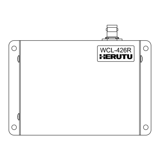
3.Part Names and Descriptions Connector for antenna Mounting hole DC jack LAN Connector Setting switch LED monitor Name Function Connector for Connector for connection to the antenna. (BNC-J Connector) antenna Attach the supplied antenna. Mounting hole of φ4.5 × 4 Mounting holes DC jack DC jack for connection of the included AC adapter. -
Page 10: 4.Drawing
4.Drawing 4-φ4.5 Mounting hole 4-φ4.5取付穴 (41) -
Page 11: 5.Prepare To Start Communication
5.Prepare to Start Communication Before use of the receiver, set each receiver according to the use environment. Set the IP address and other required items of the receiver by using Lantronix’s Windows-based software, “Device Installer”. 5-1.Installation of "Device Installer" Download “Device Installer” from Lantronix’s WEB site (https://www.lantronix.com/products/deviceinstaller/) to install it on your PC. - Page 12 To change the IP address, select the address of the X port on the left of the screen. IP assignment button Device details Select IP address to change - Fig. 2 Select IP address of Xport to change - Click “IP assignment button”, and the screen is displayed as shown in Fig.3. Select to assign an IP address automatically or specify an IP address directly.
- Page 13 Enter the IP address, subnet mask and default gateway. *Before setting an IP address, obtain permission from the network administrator. Click “Next” button. IP settings IP address Subnet mask Default gateway Next - Fig. 4 IP address input screen - Assignment Click “Assignment”...
- Page 14 When the setting is completed, the “Exit” button becomes active. It may take some time before the setting is completed. Please wait until the setting is completed. Assignment Task progress Completed Finish - Fig. 6 Input end screen - Click the “Exit” button, and the screen is displayed as shown in Fig.7. Confirm if the IP address has changed properly.
- Page 15 ■Change Password The WEB screen (Web Manager) inside X port requires user authentication by password. Change the default password in the following procedure. CAUTION Leaving the default password can cause a security risk to the product. Be sure to change the default password.
- Page 16 On the “Web Manager” screen in Fig.10, click the “Server” button. “Server” button. - Fig. 10 Web Manager initial screen -...
- Page 17 Click the “Server” button, and the “Server Settings” screen in Fig.11 is displayed. ① Set the “Enhanced Password” radio button to “Enable”. ② Enter a new password (up to 16 characters) in the “Telnet/Web Manager Password” field. ③ Enter the same password as ② in the “Retype Password” field. ④...
-
Page 18: 6.Settings
6.Settings Use the rotary switch, DIP switches or Ethernet communication command to set the receiver. Details of the settings and methods for changing the settings are as follows: Turn OFF the power of the main unit before changing the settings of the rotary switch or the DIP switch. Setting by Ethernet communication Setting contents Setting by switch... - Page 19 ■Ethernet communication command settings Select Valid/Invalid for the Ethernet communication command. When this setting is “Valid”, the devices are set to the setting of the Ethernet communication command. The settings are stored until the power is ON next time. When this setting is “Invalid”, the devices are set to the setting of the rotary switch or the DIP switch. When this setting is “Invalid”, the receiver returns an error response after receiving the Ethernet communication command and the command will not be reflected as the setting of the device.
-
Page 20: Communication Command Function
7. Communication Command Function The Ethernet communication command allows information acquisition and device settings of the receiver to be changed. To use the Ethernet communication command function, “Ethernet communication command settings” of the DIP switch, SW1-1 must be valid. 7-1.Information Acquisition Command @?Command<Space>[Param]<Terminal code>... - Page 21 When the information acquisition command terminates normally, the command execution result is as follows: When a response with multiple values is included, a response separated with commas for each data element is returned. <First code>Command<Space><result1>,・・・,<result n><Terminal code> “@?” Fixed (40H,3FH) First code Command Command for acquiring each information...
- Page 22 <Error code> Error group (X) Error number (Y) Meaning No first code (“@”) Non-existent command Character code is included in the set value Command format error Excessive command string length Out of the set value range Ethernet communication command invalid Serial number reading error Receiver settings reading error Other errors...
- Page 23 Transmission format Execution result Meaning @?Version @?Version 1.00 Software version acquisition @?ModelName @?ModelName WCL-426R Type acquisition @?SerialNumber @?SerialNumber A00001 Serial number acquisition *1: Example when the soft version is 1.00. *2: Example when the serial number is A00001. ■Information acquisition/setting command...
-
Page 24: 8.Installation Procedure
8.Installation Procedure 8-1.Receiver Installation Communication performance highly depends on the installation environment. Install the receiver as follows. ・ Keep the antenna away from metal sheets or wires, and prevent the antenna from becoming parallel to them. ・ Keep the antenna away from noise sources. ・... -
Page 25: Lan Connector
8-2.LAN connector For the connector use RJ45 type. 1・・・・・・8 The pin specifications are shown in the following table. Pin number Signal name TX+[Transmission data(+)] TX-[Transmission data(-)] RX+[Receiving data(+)] Unused Unused RX-[Receiving data(-)] Unused Unused Please use the cable of the category 5 or higher standard. -
Page 26: 9.Description Of Operation
Number of Item Contents bytes “@!CallData” ASCII string First code Space Space (20H) “WCL-426R” Model ASCII string Serial number in ASCII Serial number One alphabet letter + 5-digit serial number identifier, starting with “A00001”. Channel settings ASCII string: “00” – ”10”... -
Page 27: Led Monitor
9-2.LED Monitor Check the status of the power supply, wireless communication and wired communication on the LED monitor. Wireless communication LED (Red/Green) Wired communication LED (Red/Green) Power supply LED (Red) LAN connector LED (Orange/Green) ■At power ON The power LED lights up (Red). The LEDs for wireless communication and wired communication light up in orange, and then go out after 10 seconds. - Page 28 ■LAN connector Link LED Activity LED Link LED Activity LED LED color Contents LED color Contents Lights off Unconnected Lights off No communication Communicating in half duplex Orange LED light 10Mbps Orange LED light (Turns ON only during communication) Communicating in full duplex Green LED light 100Mbps...
-
Page 29: Processing At Power On
9-3.Processing at Power ON At power ON, the receiver reads the settings required to work. If the receiver fails to read them, the LED indication and settings may be forcibly initialized. ■Read serial number At power on, the receiver reads the serial number stored in the code flash region. If an error occurs while reading the serial number, the LEDs for wireless communication and wired communication blink in orange (blinking interval of 100msec). -
Page 30: After Service And Warranty
This regulation (hereinafter referred to as the "Regulation") is for post-shipment warranty provided by HERUTU ELECTRONICS CORPORATION (hereinafter referred to as the "Company") so that you can use the Company's product you have purchased with confidence. The Regulation does not apply to special order products (custom products). - Page 31 This regulation (hereinafter referred to as the "Regulation") shall be applied to paid repair service (hereinafter referred to as the "Service") provided by HERUTU ELECTRONICS CORPORATION (hereinafter referred to as the "Company"). The Regulation does not apply to special order products (custom products).
- Page 32 the warranty regulation" and "from the sales start date to the end date of the repair period (seven years from the production end date)". However, please note that the end date of the repair implementation period may be earlier depending on the availability and procurement status of repair parts. Establishment of contract The contract shall be established when the customer approves the quotation presented by the Company and issues an order form before the end of the repair implementation period.
- Page 33 failure, it will not be able to carry out repairs and will not provide an estimate. If a technical investigation is required to reproduce the failure, the Company will estimate the cost of reproducing the failure. Return of unrepaired product If the Company does not estimate the cost of the Service due to reasons such as being unable to reproduce the failure, it will return the Product for repair to the customer.
- Page 36 HERUTU ELECTRONICS CORPORATION 422-1 Higashimikata-cho, Kita-ku, Hamamatsu, Shizuoka, 433-8104 Japan (Sales dept) TEL.+81-53-438-3555 FAX. +81-53-438-3411 Website URL https://www.herutu.co.jp/en/ E-mail info@herutu.co.jp...
Need help?
Do you have a question about the WCL-426R and is the answer not in the manual?
Questions and answers