Table of Contents
Advertisement
Quick Links
Betriebs- und Montageanleitung AvanFit 400
Operating and Assembly Instructions AvanFit 400
Instructions de service et de montage AvanFit 400
Gebruiks- en montagehandleiding AvanFit 400
Istruzioni per il montaggio e l'uso AvanFit 400
Instrucciones de servicio y montaje AvanFit 400
Instruções de operação e montagem AvanFit 400
Drifts- og samlevejledning AvanFit 400
Bruks- og monteringsanvisning AvanFit 400
Bruks- och monteringsanvisning AvanFit 400
İşletim ve Montaj Kılavuzu AvanFit 400
Руководство по монтажу и эксплуатации AvanFit 400
Instrukcja obsługi i montażu AvanFit 400
Provozní návod AvanFit 400
Návod na obsluhu AvanFit 400
Art. no. 9 257 330
de
en
fr
nl
it
es
pt
dk
no
sv
tr
ru
pl
cz
sk
Advertisement
Table of Contents

Related Manuals for Hettich AvanFit 400


Summary of Contents for Hettich AvanFit 400
- Page 1 Betriebs- und Montageanleitung AvanFit 400 Operating and Assembly Instructions AvanFit 400 Instructions de service et de montage AvanFit 400 Gebruiks- en montagehandleiding AvanFit 400 Istruzioni per il montaggio e l’uso AvanFit 400 Instrucciones de servicio y montaje AvanFit 400 Instruções de operação e montagem AvanFit 400...
-
Page 2: Foreword
Email: HPH-service@de.hettich.com OPERATING INSTRUCTIONS: Hettich Maschinentechnik GmbH & Co. KG © 2020 von Hettich Maschinentechnik GmbH & Co. KG Copyright to the operating instructions The copyright to these operating instructions remains with Hettich Maschinentechnik GmbH & Co. KG. These operating instructions are intended for the operating personnel. -
Page 3: Table Of Contents
Contents Foreword 8. Operation Contents 8.1 Prerequisites for operating the machine 1. Introduction 8.2 Operating mode 1.1 Rating plate 8.3 Switching machine ON 1.2 Information for the owner 8.4 Sequence of movements 8.5 Switching machine OFF 1.3 Information on signs, symbols and markings 2. -
Page 4: Introduction
The machine will only be assembled and installed by persons instructed to do so by Paul Hettich GmbH & Co. KG. This also applies in particular to starting it up for the first time. -
Page 5: Information For The Owner
Without the consent of Paul Hettich GmbH & Co. KG, the machi- followed. ne owner must not make any additions, alterations or modifica- Caution tions to the machine. -
Page 6: General
2. General 2.1 Intended use 2.2 Foreseeable incorrect use Warning Warning Hazards may occur if the system is used incor- The machine must only be used for its intended rectly! purpose and be in a perfectly safe condition. The following situations in particular are deemed to be foreseeable hazardous situations: Operating safety is only guaranteed if the machi- •... -
Page 7: Description Of The Machine
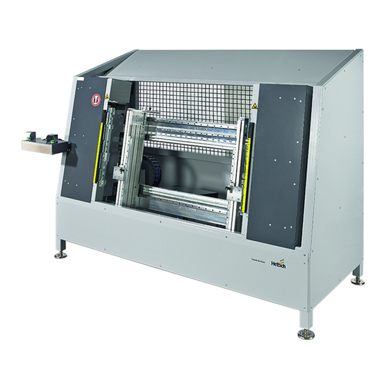
2. General 2.3 Description of the machine Space required for the machine The space required by the drawer assembly jig is largely AvanFit YOU 400 is only used for automatically assembling Avan- governed by the dimensions of the machine frame. Tech YOU drawers. -
Page 8: Safety
3. Safety The machine reflects the state of the art and is built in ac- 3.1 Residual risk cordance with recognised safety regulations. Note Hazard zones are made safe in compliance with the regulations. Handling the machine involves residual hazards The machine may present hazards if it is used by untrained per- that could not be eliminated by design measures. - Page 9 3. Safety Removing or modifying safety guards present a risk of injury! Switch o the main switch before removing, opening safety Caution guards or before carrying out maintenance and cleaning Pressure escaping from the compressed air sys- work on them. tem presents a risk of injury! Prevent main switch from switching back on again.
-
Page 10: Safety Rules For Servicing Work
3. Safety 3.2 Safety rules for servicing work Before carrying out maintenance work on the machine, you must Electrical energy: disconnect it from the power supply. For this reason, always heed Switch o electrical energy via the main switch on electrical the following 5 safety rules before commencing work on electri- cabinet. -
Page 11: Noise
3. Safety 3.3 Noise 3.5 Training and instruction The A weighted equivalent continuous sound level at the place As owner, you must inform and instruct the operating personnel where work is performed with this machine is 75 dB (A). in respect of applicable legal and accident prevention regulations as well as the safety guards fitted. -
Page 12: Personnel Qualifications
3. Safety 3.7 Personnel qualifications The following table shows specific groups of persons as well as the activities which these groups of persons are allowed to per- form on the machine. Instructed operating personnel Instructed operating personnel are individuals who, by virtue of their knowledge and practical experience, are suitable and qualified to perform the requisite activities in a safe and reliable manner. -
Page 13: Description Of The Machine
4. Description of the machine 4.1 Technical specifications 4.2 Safety guards on the machine Designation: Drawer assembly jig The machine is fitted with the following safety guards: AvanFit YOU 400 • Emergency stop button • Mechanical guards Mechanical system no.: M809___ (see rating plate) Year of manufacture: Note... -
Page 14: Emergency Stop Button
4. Description of the machine 4.2.1 Emergency stop button 4.2.2 Mechanical protective guards The machine has an emergency stop button. On activating an The machine is fitted with mechanical guards to protect sta emergency stop by means of the emergency stop button, ha- working with it. -
Page 15: Machine Controls
4. Description of the machine 4.3 Machine controls 4.3.1 Main switch and set up switch The machine has several operating controls that are used for The power circuit breaker with main switch function is located on controlling and monitoring. the switch cabinet. Fig. -
Page 16: Further Controls
4. Description of the machine 4.3.2 Further controls 4.4 Labelling on the machine You will find the following labels on the machine: Area: Electrotechnical equipment Warning of hazards from electrical current Area: Infeed (insertion zone) Fig. 8: Operator panel on the machine Description of controls Function Mushroom push/pull "emergency stop"... -
Page 17: Infeed And Removal Stations
4. Description of the machine 4.6 Infeed and removal stations Fig. 9: Infeed and removal station... -
Page 18: Software
5. Software 5.1 SIMATIC Mobile Panel 5.2 SIMATIC operator panel The machine is operated and its current status displayed by me- 5.2.1 Interface basics ans of SIEMENS SIMATIC Mobile KTP400. The operating structure as well as individual controls are descri- The general machine controls as well as user interface navigation bed on the following pages. - Page 19 5. Software Clear malfunction button (2) Energy status Function Control colours Explanation The colour coded energy status display bar is shown in each screen. The energy status is derived from set up switch and guard door (open, closed) constellations which are described in Section There is no mal- function 3.2 Energy status.
-
Page 20: Main Menu" User Interface
5. Software 5.2.2 "Main Menu" user interface (4) User interface navigation In the User interface navigation columns, the buttons shown The Main menu page is the highest level in the operating struc- below let you navigate to other user interfaces. The relevant page ture. -
Page 21: Service" User Interface
5. Software 5.2.3 "Service" user interface 5.2.4 "Settings" user interface This operating level provides general information on the machine This is where specific settings can be made for the drawer being and enables you to make further settings. General information on produced. -
Page 22: Servo" User Interface
5. Software 5.2.5 "Servo" user interface The Servo user interface displays the status of the drive. Various settings can also be made. The Servo screen displays servo information, such as status and position. A detailed description of the Servo screen is provided below. (1) Axis status (2) Select target position (3) (4) Actual, target... - Page 23 5. Software (10) Step width Function Controls Explanation The inching buttons Step width determines the distances the axis is to cover while can be used to move jogging. At a value of 0, the axis can be jogged steplessly. This the servo by hand in the "Automatic means that the axis continues moving in the relevant direc-...
-
Page 24: Malfunction Screen" User Interface
5. Software 5.2.6 "Malfunction screen" user interface The interactive malfunction mask is displayed as soon as a malfunction occurs in the machine. Once the cause has been eliminated, the malfunction can be cleared and the machine or station sequence continued. (2) Malfunction text (1) Malfunction localisation Fig. -
Page 25: Transportation And Installation
6. Transportation and installation The machine must only be transported and installed by the ma- Note nufacturer or under the manufacturer's supervision. You must observe the following regulations to ensure secure transportation: The machine cannot be transported as one unit. Lifting and load securing equipment in compli- Installation and dismantling work must be carried out by quali- ance with accident prevention regulations. -
Page 26: Installation And Setting Up
6. Transportation and installation 6.2 Installation and setting up An even standing surface with a su cient load capacity is essen- tial for setting up the machine in a proper and safe manner. Level out any unevenness in the standing surfaces to ensure that the machine is not distorted. -
Page 27: Starting Up For The First Time
7. Starting up for the first time The following instructions are to be understood as minimum Warning recommendations. Risk of injury from residual energy! Depending on operating conditions, further instructions may be There is a risk of injury if the machine starts up added to maintain the quality of the work the machine delivers. -
Page 28: Checking For Proper Working Order Without Material
7. Starting up for the first time Before starting up the machine for the first time, check to make 2) right and left (top / bottom) sure that: • the machine has been installed in accordance with the regu- lations specified, •... -
Page 29: Checking For Proper Working Order With Material
7. Starting up for the first time 7.1.2 Checking for proper working order with material Once the machine has been checked without material and run in, it is put into operation with components under operating conditions. Note As you did on starting up without material, listen for unusual noises and check to see if there is any heat buildup. -
Page 30: Operation
8. Operation 8.1 Prerequisites for operating the machine 8.2 Operating mode The following prerequisites must be met to operate the machine: The machine can be operated in various modes: • No safeguards in place from servicing work • Set up mode (key operated switch) •... -
Page 31: Sequence Of Movements
8. Operation 8.4 Sequence of movements Note Setting drawer width (standard and custom widths) Make sure that the same setting is selected on both sides (left and right) for drawer depth. Setting the drawer side profile receiver • Enter nominal box dimensions (min. 275mm / max. 1200mm) via the control panel. - Page 32 8. Operation Setting tolerance plates • To adjust the unit, turn the lever outwards by 90° and pull / push the receiver element to the required position. Now turn the lever back again and let it engage. Repeat process on opposite side. Note Make sure that the setting for the drawer side profile contour is the same on both sides (left...
- Page 33 8. Operation Setting rear panel and drawer side profile height • Pull latch bolts and move stop to chosen rear panel height. Note Repeat process on opposite side. The values on the "tolerance bar" scale and the "drawer depth stop" scale must agree Unused tolerance plates are temporarily stored on the jig.
- Page 34 8. Operation Setting pressure stamp Pull the adjusting bolt into the REAR position and snap it • into place: drawer side profile height 101 / 139 / 187 / 251mm Repeat process on opposite side! Hinweis Make sure that the same setting is selected on both sides (left and right) for the pressure stamp! •...
-
Page 35: Switching Machine Off
8. Operation 8.5 Switching machine OFF Turn OFF the main switch on the control cabinet ("0/OFF" setting) Prevent main switch from being switched back on again without authorisation. Switch o compressed air supply. • Place drawer rear panel and position it as far as the stop. Fig. -
Page 36: Setting Up
9. Setting up Note Setting up work must only be performed by qualified sta (referred to below as "operator") who, on the basis of their specialised training, experience and instruction, possess su cient knowledge about: • Safety rules • Accident prevention regulations •... -
Page 37: Troubleshooting
Once the malfunction message on the operator panel is closed, in the loss of product liability and liability on the you can start assembling drawers. part of the manufacturer for resultant damage. If it does not, please contact Hettich Customer Service (see page... -
Page 38: Malfunction Light Flashing
Malfunctions can be caused by: faulty end position sensors maladjusted end position sensors faults valves faulty cylinders Once the malfunction message on the operator panel is closed, you can start assembling drawers. If it does not, please contact Hettich Customer Service (see page 2). -
Page 39: Servicing And Maintenance
11. Servicing and maintenance All servicing measures aim to ensure safe machine operation. Danger They guarantee constant product quality and prolonged machine Danger to life from manipulating the protec- life. tive guards! Manipulated safety guards will not provide any Carry out servicing work with care. protection in the event of a hazard. - Page 40 11. Servicing and maintenance Warning Warning Risk of injury! Risk of injury from objects left in the machi- Never remove safety guards. Never modify safety guards to take the machine Objects (e.g. components, tools) left on or in out of operation! the machine can be caught up, hurled out or Rectify malfunctions impairing work safety.
-
Page 41: Check Labelling And Warning Signs
11. Servicing and maintenance Warning Warning Risk of injury from load moment! Risk of injury from falling or tripping over! Brake and gear brake motors, gear shafts, drive Soiling, residual operating consumables and au- shafts and brakes can in some cases be subject xiliary materials as well as any objects left lying to high levels of load torque. -
Page 42: Inspection Schedule
11. Servicing and maintenance Note Check all safety guards at least once before the start of each shift to make sure that they are fitted and undamaged (visual inspection). Also check the emergency stop button for proper working order once a year. Note Please also note that all tests / inspections must be documented. -
Page 43: Cleaning
12. Cleaning Warning When cleaning with liquids, please bear in mind that none of the Risk of injury from cleaning agents! cable connections, seals, switches, lamps and displays must be Any cleaning work involving contact with or cleaned with high or medium pressure machines. inhalation of dangerous liquids (e.g. -
Page 44: Taking Out Of Service
13. Taking out of service When taking the machine out of service, disconnect it from the power and compressed air supply to dissipate the residual or stored energy. Danger Danger from electric shock! Even after the machine is switched o , the fol- lowing cables in the switch cabinets are still live: •... -
Page 45: Disposal
Note The EC declaration of conformity given by Hettich Maschinentechnik GmbH & Co. KG will lose its validity if non approved replacement parts are installed. The lists of replacement and wearing parts can be found in the documentation from the various component manufacturers. -
Page 46: Replacement And Expendable Parts
Drawer assembly jig AvanFit YOU 400 Note The EC declaration of conformity given by Hettich Maschinentechnik GmbH & Co. KG will lose its validity if non approved replacement parts are installed. The lists of replacement and wearing parts can be found in the documentation from the various... -
Page 47: Ec Declaration Of Conformity
16. EC Declaration of Conformity Attached as an annex... - Page 48 Paul Hettich GmbH & Co. KG Vahrenkampstr. 12-16 32278 Kirchlengern...
Need help?
Do you have a question about the AvanFit 400 and is the answer not in the manual?
Questions and answers