
Related Manuals for Sleipner SRHV240


Summary of Contents for Sleipner SRHV240
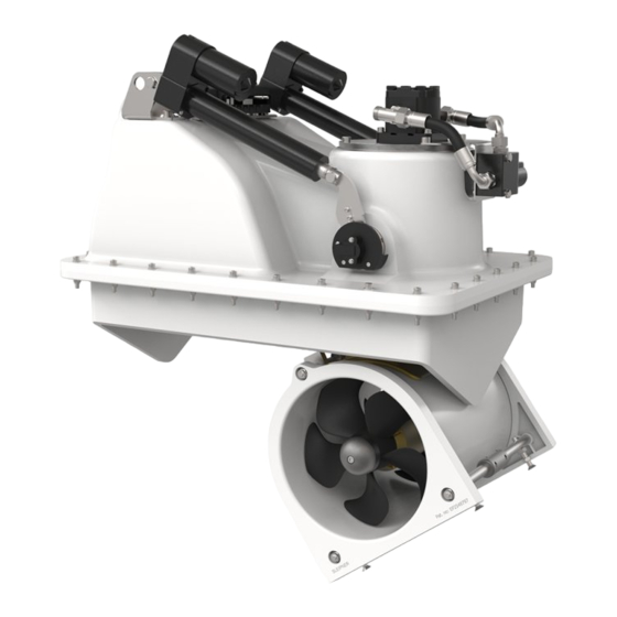
- Page 1 Installation Guide For Hydraulic Retractable Thruster Models SRHV240, SRHV320 DOCUMENT ID: SLEIPNER MOTOR AS 2933 REVISION: P.O. Box 519 DATE: N-1612 Fredrikstad 2023 Norway LANGUAGE: www.sleipnergroup.com...
-
Page 2: Table Of Contents
Accidental activation of the retract mechanism can cause serious injury due to the high-pressure force used for closing the hatch. IF operating the hatch during any work/ maintenance around or inside the retract hatch, USE CAUTION. MC_0411 Sleipner Motor AS P.O. Box 519, Arne Svendsensgt. 6-8 N-1612 Fredrikstad, Norway MC_0020 SH 240 &... -
Page 3: Responsibility Of The Installer
Any attempt to directly control or connect into the S-Link™ control system without a designated and approved interface will render all warranties and responsibilities of all of the connected Sleipner products. If you are interfacing the S-Link™ bus by agreement with Sleipner through a designated Sleipner supplied interface, you are still required to install at least one original Sleipner control panel to enable efficient troubleshooting if necessary. -
Page 4: Product Measurements
Product Measurements MC_0168 SRH 240 Measurement Measurement description code inch Height 15.4 Length 27.1 Additional Length Width 18.9 Internal Diameter 9.80 Water Depth 9.80 Retract Depth 14.2 Retract Width 13.7 Mould Width 16.3 Mould Height MG_0422 SH 240 & SH 320 2933 2023... - Page 5 Product Measurements MC_0364 SRH 320 Measurement Measurement description code inch Height 17.9 Length 33.2 Width 22.83 Internal Diameter 11.8 Water Depth 11.8 Retract Depth 17.5 Retract Width 16.3 Mould Width 18.9 Mould Height MG_0421 SH 240 & SH 320 2933 2023...
-
Page 6: Product Specifications
Hull Specifi cations MC_0609 Use sealants, adhesives or bonding material compatible with the materials of your vessels hull and Sleipner product. Product Specifi cations MC_0169 Light Duty Heavy Duty Power Output Weight Maximum Product Lubrication Thrust is kg Thrust is kg... - Page 7 Connection of Hydraulic Hose to Motor MC_0172 Follow the defi ned hose specifi cations to connect hydraulic hoses to the motor. Motor type Port A/B Drain Port 22L, Metric DIN 2353 1/4” BSP 22L, Metric DIN 2353 1/4” BSP 22L, Metric DIN 2353 1/4”...
-
Page 8: Stern Tunnel Installation
Positioning of the Retract Thruster Retract Thruster Ensure enough space for the complete retract unit including room for installation of SRF flange and for future service. Allow 100 mm of clear space around the thruster for moulding of the SRF flange. Ensure that when the thruster is deployed the depth of the propeller exceeds the minimum tunnel depth defined in below table. - Page 9 Preparing a Sandwich Hull for Retract Systems MC_0067 For vessels with sandwich hull construction, additional reinforcement of the area around the SRF flange is required. Cross section of a sandwich core hull Inner laminate Core Outer laminate Gel coat 1. To achieve maximum strength and bonding in the area around the installation of the SRF flange remove the inner laminate and core material to expose the outer laminate.
- Page 10 Marking and Trimming of SRF Flange MC_0068 Identify the location of the thruster considering space required for installation, operation and future maintenance. Flip the SRF flange upside down and position it at the identifi ed installation location. Use the internal edge to mark the hull for cutting the thruster hatch.
- Page 11 Marking and Trimming of SRF Flange MC_0068 Prepare for cutting the hatch door. Drill 4 holes at a 45º angle towards the starboard and port side. (NB: Cutting the hatch from outside the hull the 4 drill hole from the internal marked corners will aid in determining the hatch profi le from the outside.) The hatch opening must be cut at an angle of 45º...
- Page 12 Installation Pre-check MC_0068 Temporarily set up the complete installation to ensure no conflicts during the fi nal operation of the thruster. Use epoxy fi ller in the 4 corners of the SRF flange and set it over the hatch. Attach the retract housing retract flange with 4 corner screws to hold. Use polyester or resin to attach the hull hatch to the retract unit.
- Page 13 Required Modifi cations After Pre-check MC_0068 ! Please refer to the graphic for special considerations relating to your model ! To increase the space between the hatch and the hull the entire SRF flange and motor must be raised at the stern end. With the hatch in the open position raise the stern end of the SRF flange and motor until the appropriate clearance is achieved.
- Page 14 SRF Flange Installation MC_0068 Start the laminating with a strong attachment point in each corner between the hull and the outside of the lower unit. Use epoxy and fi breglass cutting or similar, which laminating material is the boat builders responsibility. Before grinding of hull and SRF flange, precautions must be taken against grinding dust inside the boat.
-
Page 15: Motor Installation
Motor House Installation MC_0068 ! Please refer to the graphic for special considerations relating to your model ! Apply MS Polymer or equivalent on SRF flange top surface to seal and avoid water leakage. (NB: Ensure that glue is compatible with SRF and thruster case materials.) Place the upper thruster Housing down on the SRF flange. - Page 16 Hatch Installation MC_0068 ! Please refer to the graphic for special considerations relating to your model ! Fit pin bolts to the lower tunnel rods. The ends of the bolts must be sharp to create marks in the hatch. The pin bolts must be at the correct height so the hatch will fi t in its inner position.
- Page 17 Motor to House Installation MC_0173 ! Please refer to the graphic for special considerations relating to your model ! Install the motor onto the motor bracket ensuring both the couplings and the drive shafts have locked together. The motor must be installed with the solenoid facing the control box.
- Page 18 Connection of Hydraulic Hose to Motor MC_0172 Follow the defi ned hose specifi cations to connect hydraulic hoses to the motor. Motor type Port A/B Drain Port 22L, Metric DIN 2353 1/4” BSP 22L, Metric DIN 2353 1/4” BSP 22L, Metric DIN 2353 1/4”...
- Page 19 Oil Tank Installation MC_0023 ! Please refer to the graphic for special considerations relating to your model ! Install the oil container above the waterline by at least 20% of the distance from the waterline to the centre of the tunnel. This ensures enough overpressure for the oil in the gear leg.
- Page 20 Wiring Diagram Hydraulic Retract Thruster The Top wiring diagram is for a single bow or stern thruster system Control panel See S-Link System Description chapter for detailed information on installation of S-Link Power cable and additional S-Link components. S-Link Backbone cable S-Link Spur cable PHC-3 12V/24V...
- Page 21 MC_0120 S-Link is a CAN-based control system used for communication between Sleipner products installed on a vessel. The system uses BACKBONE Cables as a common power and communication bus with separate SPUR Cables to each connected unit. Only one S-Link POWER cable shall be connected to the BACKBONE Cable.
- Page 22 Check drive shaft alignment MC_0069 IMPORTANT Before the thruster motor is operated, check the drive shaft alignment is completely straight when it reaches the end position form the control panel operation: 1) Connect power to thruster and S-link system. 2) Sett DIP-switch on the controller to 0000. 3) Turn on the panel.
-
Page 23: Control Panel Installation
Control Panel Installation MC_0398 For Control Panel installation please refer to the Installation Guide accompanying the control panel to be installed. Installation Guide Control Panel SLEIPNER MOTOR AS DOCUMENT ID: P.O. Box 519 REVISION: N-1612 Fredrikstad DATE: Norway LANGUAGE: www.sleipnergroup.com SH 240 &... - Page 24 Post Installation Checklist MC_0033 []..The bolts holding the gear leg and main bracket together are tightened correctly. []..The bolts holding the motor to its bracket are tightened correctly. []..All electrical connections are clean, dry and tight, and the correct cable, fuse and main switch size.
-
Page 25: Service And Support
11. This warranty gives you specific legal rights, and you may also have other rights which vary from country to country. Patents MC_0024 At Sleipner we continually reinvest to develop and offer the latest technology in marine advancements. To see the many unique designs we have patented visit our website www.sleipnergroup.com/patents SH 240 & SH 320... - Page 26 Notes MC_0037 ..............................................................................................................................................................................................................................................................................................................................................................................................................................................................................................................................................................................................................................................................................................................................................................................................................................................................................................................................................................................................................................................................................................................................................................................................................................................................................................................................................................................................................................................................................................................................................................................................................SH 240 & SH 320 2933 2023...
- Page 27 Notes MC_0037 ..............................................................................................................................................................................................................................................................................................................................................................................................................................................................................................................................................................................................................................................................................................................................................................................................................................................................................................................................................................................................................................................................................................................................................................................................................................................................................................................................................................................................................................................................................................................................................................................................................SH 240 & SH 320 2933 2023...
- Page 28 © Sleipner Group, All rights reserved The information given in the document was right at the time it was published. However, Sleipner Group cannot accept liability for any inaccuracies or omissions it may contain. Continuous product improvement may change the product specifi cations without notice.
Need help?
Do you have a question about the SRHV240 and is the answer not in the manual?
Questions and answers