Table of Contents
Advertisement
Available languages
Available languages
Quick Links
Helios Ventilatoren
MONTAGE- UND BETRIEBSVORSCHRIFT
INSTALLATION AND OPERATING INSTRUCTIONS
NOTICE DE MONTAGE ET D'UTILISATION
Zentrales Lüftungsgerät
Central ventilation unit
Unité de ventilation centrale
KWL 500 W
KWL 500 W ET
Kompaktes Wandgerät mit Wärmerückgewinnung
und EC-Technik
Compact wall-mounted unit with heat recovery
and EC technology
Centrale murale compacte avec récupération de chaleur
et technologie EC
DE
EN
FR
easy
Controls 3.0
Advertisement
Chapters
Table of Contents

Related Manuals for Helios KWL 500 W


Summary of Contents for Helios KWL 500 W
- Page 1 Controls 3.0 Zentrales Lüftungsgerät Central ventilation unit Unité de ventilation centrale KWL 500 W KWL 500 W ET Kompaktes Wandgerät mit Wärmerückgewinnung und EC-Technik Compact wall-mounted unit with heat recovery and EC technology Centrale murale compacte avec récupération de chaleur...
-
Page 2: Table Of Contents
Montage- und Betriebsvorschrift Zentrales Lüftungsgerät – KWL 500 W/W ET INHALTSVERZEICHNIS MONTAGE- UND BETRIEBSVORSCHRIFT KAPITEL 1 SICHERHEIT ................................. SEITE 3 Grundlegende Hinweise ................................. Seite 3 Warnhinweise ..................................Seite 3 Sicherheitshinweise ................................Seite 3 Einsatzbereich ..................................Seite 4 Personalqualifikation ................................Seite 4 KAPITEL 2 GRUNDLEGENDE HINWEISE ............................ - Page 3 Montage- und Betriebsvorschrift Zentrales Lüftungsgerät – KWL 500 W/W ET DEUTSCH KAPITEL 7 BEDIENUNG ................................SEITE 22 Bedienungsmöglichkeiten ..............................Seite 22 7.1.1 Lokaler Webserver ................................Seite 22 7.1.2 easyControls Cloud-Dienst ..............................Seite 22 7.1.3 Bedienelemente ................................. Seite 22 7.1.4 Gebäudeleittechnik (GLT) ..............................Seite 22 Geräteeinstellungen über easyControls 3.0 .........................
- Page 4 Montage- und Betriebsvorschrift Zentrales Lüftungsgerät – KWL 500 W/W ET KAPITEL 1 Grundlegende Hinweise Zur Sicherstellung einer einwandfreien Funktion und zur eigenen Sicherheit sind alle nachstehenden Vorschriften genau SICHERHEIT durchzulesen und zu beachten. Die national einschlägigen Normen, Sicherheitsbestimmungen und Vorschriften (z.B.
-
Page 5: Montage- Und Betriebsvorschrift
Einsatzbereich – Bestimmungsgemäßer Einsatz Das zentrale Lüftungsgerät KWL 500 W/W ET mit Wärmerückgewinnung, ist für die zentrale Be- und Entlüftung von Wohnhäusern und Etagenwohnungen konzipiert. Das Gerät ist zur Förderung normaler oder leicht staubhaltiger (Parti- kelgröße < 10 µm), wenig aggressiver und feuchter Luft, in gemäßigtem Klima und im Bereich seiner Leistungskennlinie geeignet. -
Page 6: Grundlegende Hinweise
Montage- und Betriebsvorschrift Zentrales Lüftungsgerät – KWL 500 W/W ET KAPITEL 2 Transport Das Gerät ist werkseitig so verpackt, dass es gegen normale Transportbelastungen geschützt ist. Der Transport muss GRUNDLEGENDE sorgfältig durchgeführt werden. HINWEISE Bei Weiterversand, vor allem über längere Distanzen (z.B. Seeweg) ist zu prüfen, ob die Verpackung für Transportart und -weg geeignet ist. -
Page 7: Vorschriften Und Richtlinien
Alle Ausführungen der zum Gerät gehörenden Dokumentationen müssen beachtet werden, sonst entfällt die Gewähr- leistung. Gleiches gilt für Haftungsansprüche an den Hersteller. Der Gebrauch von Zubehörteilen, die nicht von Helios empfohlen oder angeboten werden, ist nicht zulässig. Even tuell auftretende Schäden unterliegen nicht der Gewährleistung. -
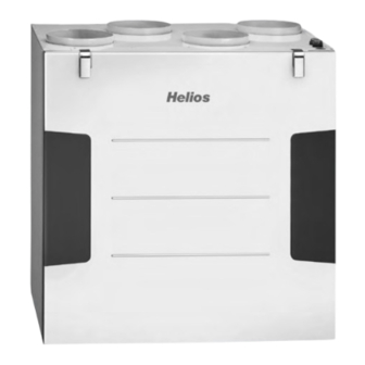
Page 8: Geräteübersicht
Der Wärmebereitstellungsgrad ist von den Faktoren Luftfeuchtigkeit und dem Temperaturunterschied zwischen Außen- und Abluft abhängig. Geräte mit Enthalpie-Wärmetauscher (KWL 500 W ET) gewinnen neben der Wärme auch Feuch- tigkeit aus der Abluft zurück, die den Räumen mit der Zuluft wieder zugeführt wird. -
Page 9: Technische Daten
Montage- und Betriebsvorschrift Zentrales Lüftungsgerät – KWL 500 W/W ET Bei Verwendung eines Heizregisters, muss das Rohrsystem 0,5m vor und nach dem Heizregister mit temperaturbeständigem bzw. nicht brennbarem Rohr versehen werden (z.B. Wickelfalzrohr) Abb. 3 Abluft Zuluft (T7) ... -
Page 10: Abmessungen
Montage- und Betriebsvorschrift Zentrales Lüftungsgerät – KWL 500 W/W ET Abmessungen Abb. 5 KWL 500 W/W ET R ø160 Abluft Fortluft Kugelsiphon Zuluft Außenluft ø12 Maße in mm Abb. 6 KWL 500 W/W ET L 167 167 167 ø160 Fortluft Abluft Außenluft... -
Page 11: Positionierung
Montage- und Betriebsvorschrift Zentrales Lüftungsgerät – KWL 500 W/W ET KAPITEL 4 Positionierung Das Gerät ist zur Installation innerhalb der Wohneinheit bzw. des Gebäudes, an der Wand oder zum Einbau in einen MONTAGE Schrank, vorgesehen. Aufgrund der Betriebsgeräusche wird empfohlen, das Gerät in einem Nebenraum (z.B. Wasch- raum, Technikraum oder Abstellraum) zu installieren. -
Page 12: Gerät Montieren
Montage- und Betriebsvorschrift Zentrales Lüftungsgerät – KWL 500 W/W ET Gerät montieren 1. Beiliegende Wandschiene waagerecht (Haltelasche nach oben) mit geeigneten Befestigungsmitteln an der Wand montieren (s. Abb. 10 und Abb. 11). Abb. 10 Abb. 11 Wandschiene Verletzungsgefahr durch Herunterfallen der Gerätetür! WARNUNG Die Gerätetür kann beim Abnehmen herunterfallen und schwere Verletzungen verursachen. -
Page 13: Kugelsiphon Montieren
Montage- und Betriebsvorschrift Zentrales Lüftungsgerät – KWL 500 W/W ET Kugelsiphon montieren Während der Heizperiode kann es durch den Prozess der Wärmerückgewinnung, im Wärmetauscher zur Bildung von Kondensat kommen. Das Kondensat muss frei aus dem Gerät ablaufen können. Hierzu muss der beiliegende Kugelsi- phon (Lieferumfang) in der Bodenwanne des Gerätes montiert werden. -
Page 14: Lüftungsleitungen Anschließen
Montage- und Betriebsvorschrift Zentrales Lüftungsgerät – KWL 500 W/W ET 6. Kondensatschlauch (Länge max. 1,5 m) an das Entwässerungssystem des Gebäudes anschließen (s. Abb. 20). Abb. 20 Kondensatschlauch DN 12 mm (Gefälle beachten!) 7. Kugelsiphon kontrollieren: – Um die Dichtheit zu gewährleisten, darf der Kugelsiphon bei bauseitiger Montage keinen seitlichen Belastungen durch den Kondensatschlauch ausgesetzt sein! –... -
Page 15: Anschlussplan
Montage- und Betriebsvorschrift Zentrales Lüftungsgerät – KWL 500 W/W ET 5.1.1 Anschlussplan Abb. 21 Modbus Leitungslänge: maximal 100 m es müssen paarw eise verdrillte Aderpaare verw endet 3x0,5 mm w erden. KWL-VOC eC Sensor* Externes Modbus Art. Nr.: 20247 KWL-BE... -
Page 16: Verdrahtungsplan
Montage- und Betriebsvorschrift Zentrales Lüftungsgerät – KWL 500 W/W ET 5.1.2 Verdrahtungsplan Abb. 22 MB_A MB_A MB_B MB_B +24V +24V RS_A RS_A RS_B RS_B siehe SS-1433 +24V RS_A +24V RS_A RS_B RS_B +11V1 +24V AN/I D/I1 Elektroverteilung +24V RM/I D/I2... -
Page 17: Erstinbetriebnahme
Montage- und Betriebsvorschrift Zentrales Lüftungsgerät – KWL 500 W/W ET KAPITEL 6 Erstinbetriebnahme Für die Erstinbetriebnahme muss das Gerät ordnungsgemäß an das Stromnetz angeschlossen bzw. mit dem Stromnetz INBETRIEBNAHME verbunden sein. Anschließend kann der Inbetriebnahmeassistent über den lokalen Webserver oder optional über das Bedienelement KWL-BE Touch (Zubehör) durchgeführt werden. -
Page 18: Einregulierung
Montage- und Betriebsvorschrift Zentrales Lüftungsgerät – KWL 500 W/W ET > Die Einstellungen für die Konfiguration des Gerätes werden angezeigt. Abb. 27 4. Gerät konfigurieren und auf „Weiter“ klicken. > Die Zusammenfassung der Einstellungen öffnet sich. 5. Einstellungen prüfen und ggf. anpassen. - Page 19 Montage- und Betriebsvorschrift Zentrales Lüftungsgerät – KWL 500 W/W ET Abb. 28 Abb. 29 Kennlinie KWL 500 W Kennlinie KWL 500 W Zuluft Abluft 10 % 10 % â â â â 20 % 20 % ê ê ê ê...
- Page 20 Montage- und Betriebsvorschrift Zentrales Lüftungsgerät – KWL 500 W/W ET 4. Die ermittelten Differenzdrücke der Zu- und Außenluftmessung in die Kennlinie des Gerätes für Zuluft (s. Abb. 28 und Abb. 30), entsprechend der im Lüftungsprofil hinterlegten Ventilatorleistungen, eintragen (vgl. Abb. 33 und Abb. 34).
- Page 21 Montage- und Betriebsvorschrift Zentrales Lüftungsgerät – KWL 500 W/W ET Ventilatorleistungen ermitteln: 1. Volumenströme aus der Auslegungsberechnung für die drei Lüftungsprofile „Zuhause“, „Unterwegs“ und „Intensiv- lüftung“ in die Kennlinie des Gerätes für Zu- und Abluft eintragen (vgl. Abb. 36). ⓘ Wir empfehlen folgende Werte in den Lüftungsprofilen zu hinterlegen: •...
-
Page 22: Volumenstrommessung Zur Einregulierung Der Anlage (Feinjustierung) Durchführen
Montage- und Betriebsvorschrift Zentrales Lüftungsgerät – KWL 500 W/W ET Abb. 38 6.3.3 Volumenstrommessung zur Einregulierung der Anlage (Feinjustierung) durchführen • Volumenströme an allen Ventilen im Zu- und Abluftstrang messen. • Volumenströme jeweils für Zu- und Abluftstränge aufsummieren. • Bei Abweichungen zu den gewünschten Volumenströmen, diese entsprechend durch Erhöhen oder Verringern an- passen. - Page 23 Montage- und Betriebsvorschrift Zentrales Lüftungsgerät – KWL 500 W/W ET KAPITEL 7 Bedienungsmöglichkeiten 7.1.1 Lokaler Webserver BEDIENUNG Das Gerät kann über den lokalen Webserver mittels einem Webbrowser, über ein mobiles Endgerät (z.B. Notebook, PC, Tablet, Smartphone) konfiguriert werden. Es ist keine Anmeldung/Registrierung des Gerätes erforderlich.
- Page 24 Montage- und Betriebsvorschrift Zentrales Lüftungsgerät – KWL 500 W/W ET ZUHAUSE Lüftungsprofil bei Anwesenheit von Personen. Folgende Parameter sind einstellbar: • Ventilatorleistung • Zuluft Hier ist die Solltemperatur für die Zuluft einzustellen. ⓘ O hne Nachheizung (optional; als Zubehör erhältlich) liegt die maximal erreichbare Solltemperatur 2-3 °C unter der Ablufttemperatur.
- Page 25 Montage- und Betriebsvorschrift Zentrales Lüftungsgerät – KWL 500 W/W ET 7.2.1.7 Wochenprogramm Abb. 40 • Wochenprogramm ein-/ausschalten • Wochenprogramm erstellen/bearbeiten Durch Klicken auf ein Feld ändert sich das Lüftungsprofil in folgender Reihenfolge (vgl. Abb. 40): Lüftungsprofil „Zuhause“ (1x klicken) Lüftungsprofil „Unterwegs“ (2x klicken) Lüftungsprofil „Intensivlüftung“...
- Page 26 Montage- und Betriebsvorschrift Zentrales Lüftungsgerät – KWL 500 W/W ET 7.2.4 Einstellungen 7.2.4.1 Sprache Gewünschte Sprache für die Benutzeroberfläche auswählen. 7.2.4.2 Freigabecode Freigabecode ändern. ⓘ Standardmäßig ist der Freigabecode 0000 voreingestellt. 7.2.4.3 Cloud-Dienst Gerät mit dem easyControls Cloud-Dienst verbinden oder Cloud-Dienst trennen. Beim Verbinden mit dem Cloud-Dienst öffnet sich die Startseite zur Anmeldung automatisch.
- Page 27 Montage- und Betriebsvorschrift Zentrales Lüftungsgerät – KWL 500 W/W ET • Not-Aus/Normalbetrieb (0 V / 24 V) • Intensivlüftung Aus/Ein (0 V / 24 V) • Normalbetrieb / Bypass (0 V / 24 V) • Wochenprogramm Aus / Ein (0 V / 24 V) •...
- Page 28 Montage- und Betriebsvorschrift Zentrales Lüftungsgerät – KWL 500 W/W ET KAPITEL 8 Gerät warten Das Gerät ist je nach Bedarf, jedoch mindestens einmal im Jahr auf Verschmutzungen und Verunreinigungen zu prüfen WARTUNG UND (Sichtprüfung). SERVICE Verbrennungsgefahr durch heiße Oberflächen! Heiße Oberflächen können schwere Verbrennungen verursachen.
- Page 29 Montage- und Betriebsvorschrift Zentrales Lüftungsgerät – KWL 500 W/W ET 8.3.2 Wärmetauscher reinigen Verbrennungsgefahr durch heiße Oberflächen! Heiße Oberflächen können schweren Verbrennungen verursachen. WARNUNG > Gerät 5 Minuten abkühlen lassen bzw. warten, bis die Ventilatoren ausgedreht sind. Verletzungsgefahr durch rotierende Ventilatoren! WARNUNG Rotierende Ventilatoren können Gliedmaße verletzen und schwere Verletzungen verursachen.
- Page 30 Montage- und Betriebsvorschrift Zentrales Lüftungsgerät – KWL 500 W/W ET Stilllegen und Entsorgen Lebensgefahr durch elektrischen Schlag! GEFAHR Bei der Demontage werden spannungsführende Teile freigelegt, die bei Berührung zu einem elektrischen Schlag führen. > Vor der Demontage das Gerät allpolig vom Netz trennen und gegen Wiedereinschalten sichern! Bauteile und Komponenten des Geräts die ihre Lebensdauer erreicht haben, z.B.
- Page 31 Montage- und Betriebsvorschrift Zentrales Lüftungsgerät – KWL 500 W/W ET...
- Page 32 Installation and Operating Instructions Central ventilation unit – KWL 500 W/W ET TABLE OF CONTENTS INSTALLATION AND OPERATING INSTRUCTIONS CHAPTER 1 SAFETY ..................................PAGE 3 Basic information ..................................Page 3 Warning instructions ................................Page 3 Safety instructions .................................. Page 3 Area of application ..................................
- Page 33 Installation and Operating Instructions Central ventilation unit – KWL 500 W/W ET ENGLISH CHAPTER 7 OPERATION ................................PAGE 22 Operating options ................................. Page 22 7.1.1 Local web server ................................Page 22 7.1.2 easyControls cloud service ..............................Page 22 7.1.3 Control elements ................................Page 22 7.1.4...
-
Page 34: Installation And Operating Instructions
Installation and Operating Instructions Central ventilation unit – KWL 500 W/W ET CHAPTER 1 Basic information In order to ensure correct operation and for your own safety, please read and observe the following instructions carefully SAFETY before proceeding. Relevant national standards, safety regulations and provisions (e.g. DIN EN VDE 0100) as well as the technical connection conditions of the energy supply company must be observed and applied. -
Page 35: Area Of Application
– Intended use The central ventilation unit KWL 500 W/W ET with heat recovery is designed for the central supply and extract venti- lation of residential houses and apartments. The unit is suitable for conveying normal or slightly dusty (particle size <... -
Page 36: Chapter 2 Basic Information
Installation and Operating Instructions Central ventilation unit – KWL 500 W/W ET CHAPTER 2 Shipping The delivery is packed ex works in such a way that it is protected against normal transport strain. The shipping must BASIC be carried out carefully. -
Page 37: Regulations And Guidelines
All versions of this documentation must be observed, otherwise the warranty shall cease to apply. The same applies to liability claims against the manufacturer. The use of accessory parts which are not recommended or offered by Helios is not permitted. Any possible damages are not covered by the warranty. -
Page 38: Chapter 3 Unit Overview
The heat recovery efficiency depends on the factors of humidity and the temperature difference between intake and extract air. Units with enthalpy heat exchangers (KWL 500 W ET) recover humidity from the extract air in addition to heat, which is returned to the rooms through the supply air. -
Page 39: Technical Data
Installation and Operating Instructions Central ventilation unit – KWL 500 W/W ET Bei Verwendung eines Heizregisters, muss das Rohrsystem 0,5m vor und nach dem Heizregister mit temperaturbeständigem bzw. nicht brennbarem Rohr versehen werden (z.B. Wickelfalzrohr) Fig. 3 Extract air Abluft... -
Page 40: Dimensions
Installation and Operating Instructions Central ventilation unit – KWL 500 W/W ET Dimensions Fig. 5 KWL 500 W/W ET R ø160 Abluft Fortluft Exhaust air Extract air Kugelsiphon Ball siphon Zuluft Außenluft Supply air Intake air ø12 Dimensions in mm Fig. -
Page 41: Chapter 4 Installation
Installation and Operating Instructions Central ventilation unit – KWL 500 W/W ET CHAPTER 4 Positioning The unit is designed for installation on the wall inside the residential unit or building or for installation in a cabinet. Due to the INSTALLATION operating noise, it is recommended to install the unit in a secondary room (e.g. -
Page 42: Install Unit
Installation and Operating Instructions Central ventilation unit – KWL 500 W/W ET Install unit 1. Install enclosed wall rail horizontally (fixing bracket at top) on the wall with suitable fixings (see Fig. 10 and Fig. 11). Fig. 10 Fig. 11... -
Page 43: Install Ball Siphon
Installation and Operating Instructions Central ventilation unit – KWL 500 W/W ET Install ball siphon During heating periods, condensate may form in the heat exchanger due to the heat recovery process. The condensa- te must be able to drain freely from the unit. The provided ball siphon (scope of delivery) must be installed in the base tray of the unit for this purpose. -
Page 44: Connect Ventilation Ducts
Installation and Operating Instructions Central ventilation unit – KWL 500 W/W ET 6. Connect condensate hose (length max. 1.5 m) to the building drainage system (see Fig. 20). Fig. 20 Condensate hose DN 12 mm (note gradient!) 7. The ball siphon must be inspected: –... -
Page 45: Connection Diagram
Installation and Operating Instructions Central ventilation unit – KWL 500 W/W ET 5.1.1 Connection diagram Fig. 21 Modbus cable length: maximum 100 m 3x0,5 mm tw isted pairs of w ires must be used. KWL-VOC eC Remote Sensor* monitoring art. nr.: 20247... -
Page 46: Wiring Diagram
Installation and Operating Instructions Central ventilation unit – KWL 500 W/W ET 5.1.2 Wiring diagram Fig. 22 MB_A MB_A MB_B MB_B +24V +24V RS_A RS_A RS_B RS_B SS-1433 +24V RS_A +24V RS_A RS_B RS_B +11V1 +24V AN/I D/I1 Distribution board... -
Page 47: Chapter 6 Commissioning
Installation and Operating Instructions Central ventilation unit – KWL 500 W/W ET CHAPTER 6 Initial commissioning The unit must be properly connected or linked to the mains power supply for the initial commissioning. The commissio- COMMISSIONING ning assistant can then run via the local web server or optionally via the control element KWL-BE Touch (accessories). -
Page 48: Adjustment
Installation and Operating Instructions Central ventilation unit – KWL 500 W/W ET > The settings for unit configuration are displayed. Fig. 27 4. Configure unit and click “Next”. > The settings summary page will open up. 5. Check settings and adjust if necessary. - Page 49 Installation and Operating Instructions Central ventilation unit – KWL 500 W/W ET Fig. 28 Fig. 29 Characteristic curve KWL 500 W Characteristic curve KWL 500 W Supply air Extract air 10 % 10 % â â â â 20 % 20 % ê...
- Page 50 Installation and Operating Instructions Central ventilation unit – KWL 500 W/W ET 4. Enter the determined differential pressures from the supply and intake air measurement in the unit characteristic curve for supply air (see Fig. 28 and Fig. 30) according to the fan outputs saved in the ventilation profile (cf. Fig. 33 and Fig.
- Page 51 Installation and Operating Instructions Central ventilation unit – KWL 500 W/W ET Determine fan powers: 1. Enter the flow rates from the design calculation for the three ventilation profiles “At home”, “Away” and “Boost” in the unit characteristic curve for supply and extract air (cf. Fig. 36).
-
Page 52: Perform Flow Rate Measurement For Adjusting The System (Fine Adjustment)
Installation and Operating Instructions Central ventilation unit – KWL 500 W/W ET Fig. 38 6.3.3 Perform flow rate measurement for adjusting the system (fine adjustment) • Measure the flow rates at all valves in the supply and extract air ducts. - Page 53 Installation and Operating Instructions Central ventilation unit – KWL 500 W/W ET CHAPTER 7 Operating options 7.1.1 Local web server OPERATION The unit can be configured via the local web server using a web browser, via a mobile end device (e.g. notebook, PC, tablet, smartphone).
- Page 54 Installation and Operating Instructions Central ventilation unit – KWL 500 W/W ET AT HOME Ventilation profile in the presence of persons. The following parameters can be adjusted: • Fan power • Supply air The target supply air temperature is adjusted here.
- Page 55 Installation and Operating Instructions Central ventilation unit – KWL 500 W/W ET 7.2.1.7 Weekly programme Fig. 40 • Activate/deactivate weekly programme • Create/edit weekly programme The ventilation profile changes in the following order by clicking on a field (cf. Fig. 40): Ventilation profile “At home”...
- Page 56 Installation and Operating Instructions Central ventilation unit – KWL 500 W/W ET 7.2.4 Settings 7.2.4.1 Language Select the desired language for the user interface. 7.2.4.2 Release code Change release code. ⓘ The release code is pre-set to 0000 as standard.
- Page 57 Installation and Operating Instructions Central ventilation unit – KWL 500 W/W ET • Normal mode / Bypass (0 V / 24 V) • Weekly programme Off / On (0 V / 24 V) • Configurable input Off / On (0 V / 24 V) ⓘ...
- Page 58 Installation and Operating Instructions Central ventilation unit – KWL 500 W/W ET CHAPTER 8 Unit maintenance The unit must be checked for contamination and dirt (visual inspection) as needed or at least every year. SERVICE AND Risk of burns due to hot surfaces! MAINTENANCE Hot surfaces can cause serious burns.
- Page 59 Installation and Operating Instructions Central ventilation unit – KWL 500 W/W ET Risk of injury due to rotating fans! WARNING Rotating fans can injure limbs and cause serious injuries. > Before working on the unit, wait until the fans are turned off.
- Page 60 Installation and Operating Instructions Central ventilation unit – KWL 500 W/W ET Standstill and disposal Danger to life due to electric shock! DANGER Live parts are exposed during dismantling and touching these live parts will lead to electric shock. > Before dismantling, isolate the unit from the power supply and secure against unintentional restart! Parts and components of the fan, whose service life has expired, e.g.
- Page 61 Installation and Operating Instructions Central ventilation unit – KWL 500 W/W ET...
- Page 62 Notice de montage et d‘utilisation Unité de ventilation centrale – KWL 500 W/W ET SOMMAIRE NOTICE DE MONTAGE ET D‘UTILISATION CHAPITRE 1 SÉCURITÉ .................................. PAGE 3 Informations générales ................................Page 3 Consignes de sécurité ................................Page 3 Consignes de sécurité ................................Page 3 Domaines d‘utilisation ................................
-
Page 63: Notice De Montage Et D'utilisation
Notice de montage et d‘utilisation Unité de ventilation centrale – KWL 500 W/W ET FRANÇAIS CHAPITRE 7 COMMANDE ................................PAGE 22 Possibilités de commande ..............................Page 22 7.1.1 Serveur web local ................................Page 22 7.1.2 Service Cloud easyControls .............................. Page 22 7.1.3... -
Page 64: Informations Générales
Filet à cheveux Le filet à cheveux empêche les longs cheveux de se coincer dans les pièces mobiles. Pour le fonctionnement, le raccordement et l’utilisation, contacter Helios en cas de doutes. Des informations supplémentaires sont consultables dans les normes et textes de loi. -
Page 65: Domaines D'utilisation
Domaines d‘utilisation – Usage prévu La centrale KWL 500 W/W ET avec récupération de chaleur est conçue pour la ventilation centrale des bâtiments résidentiels et des appartements. L‘appareil est adapté au transport d‘air normal ou légèrement pollué (taille des parti- cules <... -
Page 66: Transport
Notice de montage et d‘utilisation Unité de ventilation centrale – KWL 500 W/W ET CHAPITRE 2 Transport L’appareil est emballé en usine et est protégé des dégâts de transport courants. Transporter l’appareil avec précautions. INFORMATIONS En cas de transport ultérieur, en particulier sur de longues distances (par exemple par mer), il faut vérifier si l‘emballage GÉNÉRALES... -
Page 67: Normes - Règlementations
Si toutes les consignes indiquées dans cette notice ne sont pas correctement respectées, la garantie s’annule. Idem pour les garanties constructeur Helios. L’utilisation d’accessoires, non fournis, non conseillés ou non proposés par Helios, est interdite. Tous changements ou transformations effectués sur l’appareil sont interdits, altèrent sa conformité... -
Page 68: Vue D'ensemble De L'appareil
Notice de montage et d‘utilisation Unité de ventilation centrale – KWL 500 W/W ET CHAPITRE 3 Vue d‘ensemble de l‘appareil INFORMATIONS Fig. 1 SUR LE PRODUIT ... -
Page 69: Données Techniques
Notice de montage et d‘utilisation Unité de ventilation centrale – KWL 500 W/W ET Bei Verwendung eines Heizregisters, muss das Rohrsystem 0,5m vor und nach dem Heizregister mit temperaturbeständigem bzw. nicht brennbarem Rohr versehen werden (z.B. Wickelfalzrohr) Fig. 3 air extrait Abluft air soufflé... -
Page 70: Dimensions
Notice de montage et d‘utilisation Unité de ventilation centrale – KWL 500 W/W ET Dimensions Fig. 5 KWL 500 W/W ET R ø160 Abluft Fortluft air extrait air rejeté Siphon à boule Kugelsiphon Zuluft Außenluft air soufflé air extérieur ø12 Dimensions en mm Fig. -
Page 71: Positionnement
Notice de montage et d‘utilisation Unité de ventilation centrale – KWL 500 W/W ET CHAPITRE 4 Positionnement L‘appareil est destiné à être installé au mur ou dans une armoire à l‘intérieur de l‘appartement ou du bâtiment. En MONTAGE raison du bruit de fonctionnement, il est recommandé d‘installer l‘appareil dans une salle d‘eau, un local technique ou un local de stockage, par exemple. -
Page 72: Montage De L'appareil
Notice de montage et d‘utilisation Unité de ventilation centrale – KWL 500 W/W ET Montage de l‘appareil 1. Fixer le rail porteur horizontalement (support vers le haut) sur le mur à l‘aide des fixations appropriées (voir Fig. 10 et Fig. 11). -
Page 73: Montage Du Siphon À Boule
Notice de montage et d‘utilisation Unité de ventilation centrale – KWL 500 W/W ET Montage du siphon à boule Pendant la période de chauffe, des condensats peuvent se former dans l‘échangeur à contre-courant en raison du processus de récupération de la chaleur. Le condensat doit pouvoir s‘écouler librement de l‘appareil. Le siphon à boule (inclus dans la livraison) doit être monté... -
Page 74: Raccordement Des Conduits De Ventilation
Notice de montage et d‘utilisation Unité de ventilation centrale – KWL 500 W/W ET 6. Raccorder le tube des condensats (longueur max. 1,5 m) au système d’évacuation des eaux usées du bâtiment (à un siphon) (voir Fig. 20). Fig. 20 Tubes des condensats DN 12 mm (doit être en pente !) -
Page 75: Schéma De Raccordement
Notice de montage et d‘utilisation Unité de ventilation centrale – KWL 500 W/W ET 5.1.1 Schéma de raccordement Fig. 21 Longueur du câble Modbus : 100 m maximum 3x0,5 mm Il faut utiliser des paires de fils torsadés. KWL-VOC eC Surveillance à... -
Page 76: Schéma De Câblage
Notice de montage et d‘utilisation Unité de ventilation centrale – KWL 500 W/W ET 5.1.2 Schéma de câblage Fig. 22 MB_A MB_A MB_B MB_B +24V +24V RS_A RS_A RS_B RS_B voir SS-1433 +24V RS_A +24V RS_A RS_B RS_B +11V1 +24V... -
Page 77: Première Mise En Service
Notice de montage et d‘utilisation Unité de ventilation centrale – KWL 500 W/W ET CHAPITRE 6 Première mise en service Pour la première mise en service, l‘appareil doit être correctement raccordé au réseau électrique ou branché au secteur. PREMIÈRE MISE L‘assistant de mise en service peut ensuite être mis en place via le serveur web local ou, en option, via la commande... -
Page 78: Paramétrages
Notice de montage et d‘utilisation Unité de ventilation centrale – KWL 500 W/W ET > Les paramètres de configuration de l‘appareil s‘affichent. Fig. 27 4. Configurer l‘appareil et cliquer sur „Suivant“. > Le récapitulatif des paramètres s‘ouvre. 5. Vérifier les paramètres et les ajuster si nécessaire. - Page 79 Notice de montage et d‘utilisation Unité de ventilation centrale – KWL 500 W/W ET Fig. 28 Fig. 29 Courbe caractéristique KWL 500 W Courbe caractéristique KWL 500 W Air soufflé Air extrait 10 % 10 % â â â â...
- Page 80 Notice de montage et d‘utilisation Unité de ventilation centrale – KWL 500 W/W ET 4. Entrer les pressions différentielles déterminées de la mesure de l‘air soufflé et extérieur dans la courbe caractéristique de l‘appareil pour l‘air soufflé (voir Fig. 28 et Fig. 30), en fonction des performances du ventilateur enregistrées dans le profil de ventilation (voir Fig.
- Page 81 Notice de montage et d‘utilisation Unité de ventilation centrale – KWL 500 W/W ET Déterminer les performances du ventilateur : 1. Saisir les débits volumiques issus du l‘étude pour les trois profils de ventilation „à la maison“, „en déplacement“ et „Ventilation intensive“...
-
Page 82: Réglage Par Mesure Du Débit Volumique (Réglage Fin)
Notice de montage et d‘utilisation Unité de ventilation centrale – KWL 500 W/W ET Fig. 38 6.3.3 Réglage par mesure du débit volumique (réglage fin) • Mesurer les débits sur toutes les bouches de soufflage et d‘extraction d‘air. • Additionner les débits de soufflage et d‘extraction d‘air. - Page 83 Notice de montage et d‘utilisation Unité de ventilation centrale – KWL 500 W/W ET CHAPITRE 7 Possibilités de commande 7.1.1 Serveur web local COMMANDE L‘appareil peut être configuré via le serveur web local à l‘aide d‘un navigateur web, via un appareil mobile (par exemple un ordinateur portable, un PC, une tablette, un smartphone).
- Page 84 Notice de montage et d‘utilisation Unité de ventilation centrale – KWL 500 W/W ET PRÉSENT Profil de ventilation en présence de personnes. Les paramètres suivants peuvent être définis : • Puissance du ventilateur • Air soufflé Vous régler ici la température de consigne pour l‘air soufflé.
- Page 85 Notice de montage et d‘utilisation Unité de ventilation centrale – KWL 500 W/W ET 7.2.1.7 Programme hebdomadaire Fig. 40 • Activer/désactiver le programme hebdomadaire • Créer/modifier le programme hebdomadaire En cliquant sur un champ, le profil de ventilation change dans l‘ordre suivant (voir Fig. 45) Profil de ventilation „présent“...
- Page 86 Notice de montage et d‘utilisation Unité de ventilation centrale – KWL 500 W/W ET 7.2.4 Réglages 7.2.4.1 Langue Sélectionner la langue souhaitée pour l‘interface utilisateur. 7.2.4.2 Code d‘accès Changer le code d‘accès. ⓘ Le code d‘accès 0000 est préréglé par défaut.
- Page 87 Notice de montage et d‘utilisation Unité de ventilation centrale – KWL 500 W/W ET • Ventilation intensive arrêt/marche (0 V / 24 V) • Fonctionnement normal / Bypass (0 V / 24 V) • Programme hebdomadaire arrêt/marche (0 V / 24 V) •...
- Page 88 Notice de montage et d‘utilisation Unité de ventilation centrale – KWL 500 W/W ET CHAPITRE 8 Entretien de l‘appareil L‘appareil doit être contrôlé en fonction des besoins, mais au moins une fois par an (inspection visuelle). ENTRETIEN ET Risque de brûlures en raison de surfaces chaudes ! MAINTENANCE Les surfaces chaudes peuvent causer de graves brûlures.
- Page 89 Notice de montage et d‘utilisation Unité de ventilation centrale – KWL 500 W/W ET 8.3.2 Nettoyage de l‘échangeur à contre-courant Risque de brûlures en raison de surfaces chaudes ! Les surfaces chaudes peuvent causer de graves brûlures. AVERTISSEMENT > Laisser refroidir la centrale 5 min et attendre l’arrêt complet des ventilateurs.
- Page 90 Notice de montage et d‘utilisation Unité de ventilation centrale – KWL 500 W/W ET Recyclage Risque de mort par électrocution DANGER Lors du démontage, les pièces sous tension peuvent provoquer un choc électrique en cas de contact. > Avant le démontage, débrancher l›appareil du secteur sur tous les pôles et le protéger contre toute remise en marche ! Les pièces et composants de l‘appareil qui ont atteint leur durée de vie, par exemple en raison de l‘usure, de la corro-...
- Page 91 Notice de montage et d‘utilisation Unité de ventilation centrale – KWL 500 W/W ET...
- Page 92 CH HELIOS Ventilatoren AG · Tannstrasse 4 · 8112 Otelfingen GB HELIOS Ventilation Systems Ltd. · 5 Crown Gate · Wyncolls Road · Severalls Industrial Park · Colchester · HELIOS Ventilatoren · Postfach 854 · Siemensstraße 15 · 6023 Innsbruck...
Need help?
Do you have a question about the KWL 500 W and is the answer not in the manual?
Questions and answers