Table of Contents
Advertisement
Quick Links
Advertisement
Table of Contents

Related Manuals for Teledyne Lecroy Everywhereyoulook DL02-HCM


Summary of Contents for Teledyne Lecroy Everywhereyoulook DL02-HCM
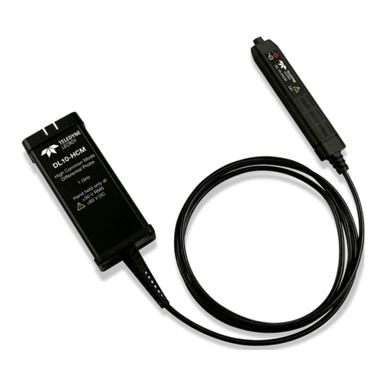
- Page 1 User Manual 60 V Common Mode Probes DL02-HCM DL05-HCM DL10-HCM...
- Page 2 Teledyne LeCroy documentation for their own internal educational purposes. Teledyne LeCroy is a trademark of Teledyne LeCroy, Inc. Other product or brand names are trademarks or requested trademarks of their respective holders. Information in this publication supersedes all earlier versions. Specifications are subject to change without notice.
-
Page 3: Table Of Contents
User Manual Contents Introduction ..............................1 Compatibility ............................. 1 Required Firmware ..........................1 Probe Components..........................2 Specifications ............................5 Safety ................................16 Precautions ............................. 16 Safe Operating Environment ........................ 17 Probe Handling ............................17 Operation ..............................18 Amplifier ..............................18 Freehand Probe Holder ......................... - Page 4 60 V Common Mode Probes Certifications ............................39 Technical Support ..........................40 Warranty ..............................40...
-
Page 5: Introduction
An optional accessory kit and high temperature solder-in tip are available for further connectivity options. Compatibility DLxx-HCM probes are compatible with Teledyne LeCroy oscilloscopes equipped with the ProBus interface running Windows® 10 Pro, Windows 7 Pro or Windows CE operating systems. See our website for all compatible oscilloscope models. -
Page 6: Probe Components
60 V Common Mode Differential Probes Probe Components The 60 V Common Mode Differential Probes consist of an amplifier and a selection of standard leads and tips. Optional accessories are available for purchase separately. - Page 7 User Manual Standard Accessories The probes are delivered with the following standard accessories. Item Description DL05 DL02 DL10 Browser Tip Attaches to the amplifier for hand-held browsing. Combines high performance with quick access to many probing points. 2” Solder-in Tip Can be soldered directly to the test points for a secure probe connection.
- Page 8 60 V Common Mode Differential Probes Optional Accessories The following optional accessories may be purchased separately. Item Description Part Number High Temperature Lead Can be used in controlled situations where DL-HCM-Hi-Temp the differential amplifier needs to be removed from an extreme temperature environment.
-
Page 9: Specifications
User Manual Specifications Full specifications are on the product datasheet. Visit teledynelecroy.com/probes. Note: Specifications are subject to change without notice. DL02-HCM DL05-HCM DL10-HCM Guaranteed Specifications Bandwidth (without leads) 250 MHz 500 MHz 1 GHz DC Gain Accuracy ± 0.5% ± 0.5% ±... - Page 10 60 V Common Mode Differential Probes Typical Bandwidth Typical bandwidth probe only or with named tip.
- Page 11 User Manual Typical Bandwidth (cont’d)
- Page 12 60 V Common Mode Differential Probes Typical Step Response Typical step response to 1 V input, probe only or with named tip.
- Page 13 User Manual Typical Step Response (cont’d) Note: Unless full bandwidth is required, we recommend applying a bandwidth filter when using the Browser to reduce peaking. The plot above shows the results.
- Page 14 60 V Common Mode Differential Probes Typical CMRR Performance Differential probes sense the voltage difference that appears between the + and – inputs, referred to as the normal or differential mode voltage. The voltage component that is referenced to earth and is identical on both inputs is rejected by the amplifier. This is referred to as the common mode voltage and can be expressed: V = (V +input...
- Page 15 User Manual numbers indicate greater rejection (better performance). The first order term determining the CMRR is the relative gain matching between the + and – input paths. You can obtain high CMRR values by precisely matching the input attenuators in a differential amplifier. The matching includes the DC attenuation and the capacitance which determines the AC attenuation.
- Page 16 60 V Common Mode Differential Probes Voltage vs. Frequency Derating...
- Page 17 User Manual Equivalent Circuits (Probe Loading) ROBE ROWSER 2” S OLDER...
- Page 18 60 V Common Mode Differential Probes PERFORMANCE OLDER 2” Y- LEAD 5” Y- LEAD...
- Page 19 User Manual TRAIGHT EADER...
-
Page 20: Safety
60 V Common Mode Differential Probes Safety To maintain the probe in a correct and safe condition, observe generally accepted safety procedures in addition to the precautions specified in this section. The overall safety of any system incorporating this product is the responsibility of the assembler of the system. These symbols appear on the probe and accessories or in this manual to alert you to important safety considerations. -
Page 21: Safe Operating Environment
User Manual CAUTION. To prevent damage to the equipment: Use only as specified. The probe is intended to be used only with compatible Teledyne LeCroy instruments. Use of the probe and/or the equipment it is connected to in a manner other than specified may impair the protection mechanisms. -
Page 22: Operation
On the top (label) side is an LED indicator that lights in the color of the channel to which the probe is connected. On the bottom is the ground lead input. 60 V common mode probes have been designed for use with Teledyne LeCroy oscilloscopes equipped with the ProBus interface. To connect to the instrument, press the amplifier connection box onto the oscilloscope’s ProBus connector until you hear a click. -
Page 23: Freehand Probe Holder
User Manual Freehand Probe Holder The optional Freehand Probe Holder is designed to position the amplifier while maintaining a steady weight on the probe tip to prevent loss of contact with the circuit under test. Turn the mounting head until the amplifier legs are in the desired position. -
Page 24: Connecting Tips
60 V Common Mode Differential Probes Connecting Tips Two inputs are available on all probe tips. The red lead connects to the + signal, and the black lead to the – signal. For accurate measurements, both the + and –must be connected to the circuit under test. - Page 25 User Manual Hi-Temp Lead The Hi-Temp lead attaches to the board exactly as do the solder-in tips. The long lead provides isolation from the DUT when it is in an environmental chamber. Y-lead Sockets The 2” and 5” Y-lead sockets provide flexibility for probing points far apart on the board, or deep within spaces where the amplifier cannot fit.
- Page 26 60 V Common Mode Differential Probes Mini-Grabbers The mini-grabbers can be used to connect to very tightly spaced pins and legs. 1. Attach a Y-lead to the side of the T-bar. 2. Pull back on the wings to expose the hook. 3.
- Page 27 User Manual Browser Tip The browser tip has a very small form factor with very low mass and variable tip spacing. It is a good, all-around solution for probing in areas with a high concentration of test points or limited free space to fit a probe. The pogo pins at the far ends of the tip provide allowance for making contact with uneven surfaces.
- Page 28 60 V Common Mode Differential Probes Ground Lead The bendable, socket-tipped ground lead can be used alone, or with the single pin or grabbers inserted for probing ground planes. Insert the right-angled pin of the ground lead into the receptacle on the underside of the amplifier body, immediately below the differential input.
-
Page 29: Using The Pcf-200 Deskew Fixture
User Manual Using the PCF-200 Deskew Fixture The PCF-200 deskew fixture may be used to determine the effect of probe input loading on the circuit under test, for verification of the probe’s response to the signal being measured, or as a convenient way to deskew the signal path. Use two BNC cables to connect a Fast Edge signal through the microstrip path you are using to the oscilloscope input channel. -
Page 30: Operating From The Oscilloscope
60 V Common Mode Differential Probes Operating from the Oscilloscope When the probe is connected to a Teledyne LeCroy oscilloscope, the displayed scale factor and measurement values will be adjusted to account for the effective gain of the probe. The probe’s internal attenuation is shown on the DLxx-CHM probe dialog, which is added to the... - Page 31 User Manual Auto Zero Auto Zero corrects for DC offset drifts that naturally occur from thermal effects in the differential amplifier. For example, the DC offset drift of the 60 V common mode probes is 250 μV/°C (worst case) referred to the output. If the probe is set to 7.5x attenuation and the ambient temperature changes by 10 °C, the DC offset drift could be as high as (250 μV/°C)(7.5)(10 °C) = 18.75 mV referred to the probe tip.
- Page 32 60 V Common Mode Differential Probes Each calibration is valid for the bandwidth, V/div and temperature (±5 ºC) at which it was performed. The probe dialog will indicate when the probe has a valid calibration and Precision Gain Calibration is in use: The probe dialog will also show that a calibration is needed when any of the calibrated conditions change by placing a red “X”...
-
Page 33: Maintenance
Service Strategy DL-HCM probes utilize fine-pitch surface mount devices. It is, therefore, impractical to attempt repair in the field. Defective probes must be returned to a Teledyne LeCroy service facility for diagnosis and exchange. CAUTION. Do not remove the covers. Refer all servicing to qualified personnel. A defective probe under warranty will be replaced with a factory refurbished probe. -
Page 34: Returning A Product For Service
60 V Common Mode Differential Probes Returning a Product for Service Contact your regional Teledyne LeCroy service center for calibration or other service. If the product cannot be serviced on location, the service center will give you a Return Material Authorization (RMA) code and instruct you where to ship the product. -
Page 35: Performance Verification Procedure
The version can be verified by selecting Utilities > Utilities Setup > Status from the oscilloscope menu bar. Contact your local Teledyne LeCroy representative or visit the software download page of our website if your oscilloscope firmware requires updating. - Page 36 SMA-BNC Adapter BNC Tee Connector Male to Dual Female Pomona 3285 Calibration Fixture 0.1 mm square pin head Teledyne LeCroy PCF200 ProBus Extender Cable Teledyne LeCroy PROBUS-CF01 Terminator, Precision BNC 50 Ω ± 0.05% Teledyne LeCroy TERM-CF01 Banana Plug Adapter (2)
-
Page 37: Preliminary Set Up
User Manual Preliminary Set Up 1. Connect the probe (without tips) to oscilloscope channel 1. 2. Turn on the oscilloscope and allow at least 20 minutes warm-up time before performing the Verification Procedure. 3. Turn on the other test equipment and allow them to warm up for the manufacturer’s recommended time. - Page 38 60 V Common Mode Differential Probes B. DC/LF Attenuation Accuracy 1. Connect the BNC tee to the output of the function generator. 2. Connect the BNC to Mini Hook cable to the BNC tee on the output of the function generator.
- Page 39 User Manual DC G ERIFY ANGE CCURACY 15. Toggle the DMM to the rear input and set the output amplitude of the signal generator to 3 Vrms ±10 mV as measured on the DMM. 16. Record the output voltage to 1 mV resolution as "Generator Output Voltage, Mid Range".
- Page 40 60 V Common Mode Differential Probes C. Probe Bandwidth 1. Disconnect the probe from the mini hooks and the ProBus extender and connect it to oscilloscope channel 1. 2. Set the RF signal generator to 1 GHz for DL10-HCM, 500 MHz for DL05-HCM or 250 MHz for DL02-HCM at +6 dBm output.
- Page 41 User Manual This completes the Performance Verification of the DLxx-HCM probe. Complete and file the test record as required to support your internal calibration procedures.
- Page 42 60 V Common Mode Differential Probes DL_____-HCM Test Record Serial Number:____________________________________________________ Asset / Tracking Number: _________________________________________ Date:______________________________________________________________ Technician:________________________________________________________ Equipment Model Serial Number Calibration Due Date Oscilloscope Digital Multimeter Function Generator RF Generator Step Description Intermediate Data Test Result Output Zero Voltage (Test limit 0 V ±5 mV) Generator Output Voltage, Top Range Effective Gain, Top Range Expected Output Voltage, Top Range...
-
Page 43: Reference
User Manual Reference Certifications For the full list of current certifications, see the EC Declaration of Conformity shipped with your product. The probe complies with: AS/NZS CISPR 11:2011 Radiated and Conducted Emissions, Group 1, Class A. IEC/EN 61010-031:2015 Safety requirements for electrical equipment for measurement, control, and laboratory use –... - Page 44 The product is warranted for normal use and operation, within specifications, for a period of one year from shipment. Teledyne LeCroy will either repair or, at our option, replace any product returned to one of our authorized service centers within this period. However, in...
- Page 46 dlxx-hcm-user-manual-eng_05apr23.pdf March, 2023...
Need help?
Do you have a question about the Everywhereyoulook DL02-HCM and is the answer not in the manual?
Questions and answers