Table of Contents
Advertisement
Quick Links
Advertisement
Table of Contents

Related Manuals for Teledyne Lecroy Everywhereyoulook ZS4000


Summary of Contents for Teledyne Lecroy Everywhereyoulook ZS4000
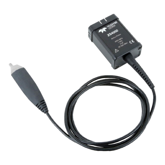
- Page 1 User Manual ZS4000 High-Impedance Active Probe...
- Page 2 Resale or unauthorized duplication of Teledyne LeCroy documentation materials is strictly prohibited. Teledyne LeCroy is a registered trademark of Teledyne LeCroy, Inc. Other product or brand names are trademarks or requested trademarks of their respective holders.
-
Page 3: Table Of Contents
Handling the Probe ................11 Connecting the Probe to the Test Circuit .......... 11 Connecting the Probe to an Oscilloscope ......... 11 Operation with a Teledyne LeCroy Oscilloscope ......12 High Frequency Measurements ............12 Performance Verification ..............16 Required Test Equipment ..............16 Test Setup and Preliminary Procedure .......... -
Page 4: Safety Instructions
ZS4000 High-Impedance Active Probe Safety Instructions Observe generally accepted safety procedures in addition to the precautions listed here. The overall safety of any system incorporating this accessory is the responsibility of the assembler of the system. Symbols These symbols appear on the probe body or in documentation to alert you to important safety considerations. -
Page 5: Introduction
With low input capacitance and high input resistance, circuit loading is minimized. The ZS4000 can be used with a variety of Teledyne LeCroy oscilloscopes with MAUI firmware version 7.1.1.2 or later (see the product page at teledynelecroy.com/oscilloscope for compatibility). -
Page 6: Standard Accessories
ZS4000 High-Impedance Active Probe Standard Accessories The ZS4000 probe is shipped with the following standard accessories: Standard Accessory Replacement Part Number Straight Tip PK-ZS-001 Pogo Tip PK-ZS-017 Bent Tip PACC-PT003 IC Tip PACC-PT005 Right Angle Socket PK-ZS-006 2.54mm Square Pin Adaptor PK-ZS-018 Offset Ground PK-ZS-016... -
Page 7: Tips
User Manual Tips Straight Tip The straight tip is rugged and designed for general probing. Fits in either probe socket. IC Lead Tip The IC Lead Tip is covered in insulation on all sides (except for a small edge), this tip was designed to prevent shorting neighboring IC leads. -
Page 8: Grounds
ZS4000 High-Impedance Active Probe Grounds 2.54 mm Square Pin Adaptor The 2.54 mm square pin adaptor fits into the ground socket of the ZS4000 probe for easy connection to standard 2.54 mm square pin spacing on a circuit board. Offset Ground The Offset Ground is designed to be attached to either socket of the probe head. -
Page 9: Leads
User Manual Pogo Ground Lead The Pogo Ground Lead allows flexibility for bending and positioning the ground lead onto hard- to -reach test points, while maintaining z-axis compliance. 2.54 mm PCB Adaptor The 2.54 mm PCB adaptor fits into the tip socket of the ZS4000 probe for easy connection to standard 2.54 mm square pin spacing on a circuit board. -
Page 10: Clips And Grabbers
ZS4000 High-Impedance Active Probe Y Lead This lead is used for both ground and input lead simultaneously. It has two sockets on one end and two square pins on the other and may be used for general purpose probing. Clips and Grabbers Channel ID Clips The Channel ID Clips can be attached to the probe cable to quickly identify to which channel the probe... -
Page 11: Probe Holder
User Manual Probe Holder Freehand Probe Holder The FreeHand lets you focus on the oscilloscope screen instead of on maintaining contact to multiple test points. It allows you to concentrate on what is really important – the waveform. It is designed to keep most of the weight on the probe tip and will prevent lost contact when a bump to the table shakes the circuit under test. -
Page 12: Zs4000 Probe Impedance
ZS4000 High-Impedance Active Probe ZS4000 Probe Impedance 10000000 1000000 100000 10000 1000 1000Hz 10kHz 100kHz 1MHz 10MHz 100MHz 1000MHz 10000MHz ZS4000 Probe Loading (Equivalent Circuit) 40 Ω 0.6pF... -
Page 13: Probe Operation
Connecting the Probe to an Oscilloscope ZS4000 probes are designed for use with Teledyne LeCroy platforms equipped with the ProBus interface. When you attach the probe output connector to the oscilloscope’s input connector, the oscilloscope recognizes the probe, provides... -
Page 14: Operation With A Teledyne Lecroy Oscilloscope
ZS4000 High-Impedance Active Probe Operation with a Teledyne LeCroy Oscilloscope When the ZS4000 probe is connected to any compatible Teledyne LeCroy oscilloscope, the displayed scale factor and measurement values are automatically adjusted. A Probe dialog appears behind the corresponding Channel dialog. - Page 15 User Manual This effect is referred to as ground lead corruption. Because it is impossible to eliminate either the L or C from this circuit, the method to improve waveform fidelity is to raise the resonant frequency beyond the bandwidth of interest in the measurement.
- Page 16 ZS4000 High-Impedance Active Probe Capacitive Loading Capacitive loading is usually the most troublesome of the three loading effects. It can affect the rise time, bandwidth and delay time measurements. At higher frequencies the capacitive loading can affect the amplitude as well as the waveshape of the measured signal by introducing an exponential response to the waveform.
- Page 17 User Manual probe source where is the probe’s input impedance and is the source impedance. For example: At 750 MHz, where the probe input impedance has reduced to 354 Ω, and a source resistance of 250 Ω the probe output amplitude is reduced ����...
-
Page 18: Performance Verification
NOTE: The correct operation of the ZS4000 controls requires software version 7.1.1.2 or higher. The oscilloscope software version can be verified by going to Utilities > Utilities Setup > Status. Contact your local Teledyne LeCroy representative or visit teledynelecroy.com if the software in your oscilloscope requires updating. - Page 19 User Manual Description Minimum Requirement Example Equipment Oscilloscope ProBus Interface; Windows- Teledyne LeCroy WaveRunner based 6 Zi or WaveSurfer MXs-B Digital Multimeter 4.5 digit Keysight 34401A (DMM) with test DC: 0.1% Accuracy Fluke 8842A-09 probe leads AC: 0.1% Accuracy Function...
-
Page 20: Test Setup And Preliminary Procedure
ZS4000 High-Impedance Active Probe Test Setup and Preliminary Procedure 1. Connect the probe to the female end of the ProBus Extension Cable. Connect the male end of the ProBus Extension Cable to channel 1 of the oscilloscope. 2. Turn on the oscilloscope and allow at least 20 minutes warm-up time for the probe and oscilloscope before performing the Verification Procedure. -
Page 21: Verification Procedure
User Manual Verification Procedure A. Output Zero Voltage Output Zero Voltage Test Setup 1. Connect one end of a BNC cable to the female BNC connector on the probe end of the ProBus extender cable. Connect the precision 50 Ω terminator to the other end of the BNC cable. - Page 22 ZS4000 High-Impedance Active Probe B. LF Attenuation Accuracy LF Attenuation Accuracy Setup 1. Disconnect the BNC tee at the power supply from the dual banana plug adapter. Connect the BNC tee to the output of the function gen erator. (Use a 50 Ω...
- Page 23 User Manual 6. Set the mode of the function generator to sine wave, the frequency to 70 Hz and the output amplitude to 5 Vrms ±10 mV as measured on the DMM. 7. Record the output voltage to 1 mV resolution as "Generator Output Voltage"...
- Page 24 ZS4000 High-Impedance Active Probe 20. Remove the banana plug adapter from the DMM and connect the precision 50 Ω terminator to the DMM, making sure that the banana plug side marked "GROUND" is connected to the LOW or COMMON input of the DMM.
-
Page 25: Zs4000 Test Record
User Manual ZS4000 Test Record Technician:_____________________________________________ Date:_____________________ Equipment Used Equipment Model Serial Number Cal Due Date Oscilloscope Digital Multimeter Function Generator Probe Lead Test Results UTPUT OLTAGE Step Description Results 1.0 mV Output Zero (Test limit ≤ ± LF A TTENUATION CCURACY Step... -
Page 26: Care And Maintenance
The ZS4000 probes utilize fine pitch surface mount devices. It is therefore impractical to attempt to repair in the field. Defective probes must be returned to a Teledyne LeCroy service facility for diagnosis and exchange. Defective probes under warranty are repaired or replaced. A probe that is not under warranty can be exchanged for a factory refurbished probe for a modest fee. -
Page 27: Returning A Product For Service
Teledyne LeCroy. Be sure to add the following: ATTN:<RMA code assigned by Teledyne LeCroy> FRAGILE 5. If returning a probe to a different country: contact Teledyne LeCroy Service for instructions on completing your import/export documents. Extended warranty, calibration and upgrade plans are available for purchase. -
Page 28: Warranty
ALL PRODUCTS UNDER WARRANTY WITH TRANSPORT PREPAID. The product is warranted for normal use and operation, within specifications, for a period of one year from shipment. Teledyne LeCroy will either repair or, at our option, replace any product returned to one of our authorized service centers within this period. -
Page 29: Certifications
2012/19/EU on Waste Electrical and Electronic Equipment (WEEE). For more information about proper disposal and recycling of your Teledyne LeCroy product, visit teledynelecroy.com/recycle. Unless otherwise specified, all materials and processes are compliant with RoHS Directive 2011/65/EU in its entirety, inclusive of any further amendments... - Page 30 ZS4000 High-Impedance Active Probe...
- Page 32 933654-00 Rev A May, 2021...
Need help?
Do you have a question about the Everywhereyoulook ZS4000 and is the answer not in the manual?
Questions and answers