Teledyne Lecroy WaveMaster 8000HD Getting Started Manual
Oscilloscopes
Hide thumbs
Also See for WaveMaster 8000HD:
- Assembly instructions (2 pages) ,
- Operator's manual (232 pages)
Table of Contents
Advertisement
Quick Links
Advertisement
Table of Contents

Related Manuals for Teledyne Lecroy WaveMaster 8000HD


Summary of Contents for Teledyne Lecroy WaveMaster 8000HD
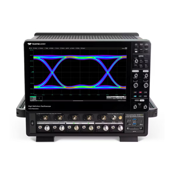
- Page 1 WaveMaster 8000HD Oscilloscopes Getting Started Guide...
-
Page 2: Key Specifications
4 ProAxial™ or 2 DBI) 2 1.85 mm (DBI) This guide is intended to help you set up a WaveMaster 8000HD Digital Channels (optional) 16 with MSO option; 9 or 18 with HDA125 oscilloscope and learn some basic operating procedures so you're quickly... -
Page 3: Operating Environment
Measuring terminals are not intended to be connected directly to supply mains. Do not operate with suspected failures. Check body and cables regularly. If any part is damaged, cease operation immediately and secure the instrument from inadvertent use. WaveMaster 8000HD Getting Started Guide... - Page 4 OVERVIEW Front of Oscilloscope The Front Panel (A) houses acquisition controls. All the knobs on the front panel function one way if turned and another if pushed like a button. The first label describes the knob’s principal “turn” action, while the second describes its “push” action. Many front panel buttons light to indicate the function is active.
- Page 5 10 MHz Ref In and Ref Out (I) connectors. HDMI and DisplayPort (D) outputs connect to external monitors. USBTMC (J) over 3.1 Gen1 connector. Use the Built-in Handles (E) to lift the instrument safely. WaveMaster 8000HD Getting Started Guide...
-
Page 6: Removing The Hard Drive
SET UP Removing the Hard Drive Connecting the HDA125 The HDA125 High-speed Digital Analyzer enables input of either 9- or 18-lines The oscilloscope features a removable solid state hard drive (SSD). of high-speed digital data. CAUTION: The hard drive is not hot swappable. Power down the Following is the recommended sequence for connecting the HDA125 to the oscilloscope before removing the hard drive cover. - Page 7 Lines from either bank can be organized into two To remove the leadset, press in and hold the buttons on each side of the logical groups and renamed appropriately. connector head to release it, then pull out the connector. WaveMaster 8000HD Getting Started Guide...
-
Page 8: Connecting Probes
SET UP Connecting Probes Most low-bandwidth probes can be attached simply by pressing the connector box onto the top-row ProBus inputs. Use care when connecting Differential High-bandwidth (DH Series) Probes to the oscilloscope ProLink or ProAxial inputs. DHxx-PL DHxx-PX 1. If present, remove the Planar-Crown ® -to-2.92mm adapter from the 1. - Page 9 Ref In or Ref Out on the back of the oscilloscope to the other instrument. Go to Timebase > Horizontal Setup > Clock Source to configure the WaveMaster 8000HD is preset to accept a DHCP address over a TCP/IP clock.
- Page 10 SET UP Touch Screen Display Features The entire oscilloscope display is an active, capacitive touch screen. You can use a pointing device, touch or alternate between the two to operate it. Upon start up, the instrument loads the MAUI oscilloscope application. At the top is drop-down menu bar (A) of actions.
- Page 11 The Add New box (E) sits next to the trace descriptor boxes. Select it to turn on new traces or add new measurements. All right-hand subdialogs apply to the left-hand object. The Delta Period subdialog configures parameter P1. Other parameters may host different measurements. WaveMaster 8000HD Getting Started Guide...
-
Page 12: Powering On/Off
SET UP Powering On/Off Setting Up Acquisition This section provides an overview of the steps required to get a signal on Always secure the power cord with the screen. All the acquisition settings, grid indicators and descriptor box the clamp. Loosen the Philips head symbols are explained in detail in the Operator's Manual. - Page 13 All input settings are reflected on the Channel Channel Descriptor Box descriptor box. See the Operator's Manual for a list of processing codes. Pre-Processing Summary Coupling Operating Gain (/div) Bandwidth Offset # Sweeps Averaged / Segment # Vertical Cursor Positions WaveMaster 8000HD Getting Started Guide...
- Page 14 SET UP Set Up Digital Inputs Digital Display Modes On instruments equipped with the Mixed-Signal Option or the HDA125, digital groups are added to the Vertical menu, and the front panel Vertical knobs also control active Digital line and bus traces. To turn on and configure digital inputs: Line trace shows high, low and transition points for each line.
- Page 15 1.85 mm inputs. Be sure your sources are connected to oscilloscope's internal 10 MHz clock. The clock signal must be connected to the 1.85 mm inputs. the Ref In input. Timebase dialog configured for DBI, combining C1 and C2 into high-bandwidth C2B. WaveMaster 8000HD Getting Started Guide...
-
Page 16: Set Up Trigger
SET UP Set Up Trigger Triggers tell the oscilloscope when to perform an acquisition. The acquisition starts as soon as the trigger is armed and all trigger conditions are met, unless postponed by a trigger Holdoff count of time or number of trigger events. When you're ready to acquire, use the Front Panel buttons or the Trigger drop-down menu to select a Trigger Mode: Auto –... - Page 17 Every time you zoom in this way, you create new zoom traces using the next available slot number, to the maximum 12. The Zoom descriptor box shows the Zoom Source and Horizontal Scale, which differs from the Timebase. WaveMaster 8000HD Getting Started Guide...
- Page 18 ANALYSIS Navigating Long Acquisitions Navigating with Zoom Stop acquisition, then create a zoom trace of the area you wish to analyze. For acquisitions >500 Mpts, measurements and math calculations take Apply math and measurements to the zoom rather than the source trace. place on only the center 500 Mpts—the "Analysis Zone".
- Page 19 Now, when Timebase is changed to 10 us/div, the trigger remains in place, grid to the left as time "expands, " but the center of trace stays in place. but the rest of the trace shifts to the right as time "expands." WaveMaster 8000HD Getting Started Guide...
- Page 20 Use the oscilloscope File menu options to save and recall data. See the panels or setup (.LSS) files and later recalled. WaveMaster 8000HD Oscilloscopes Operator’s Manual for more information Waveform data can be stored to trace (.TRC) files and later recalled into on using these features.
- Page 21 Choose Math > Memory Setup. On the Mn tab, select the trace you want stored in Copy From Waveform, then touch Copy Now. Optionally, add Notes or Labels to the stored memory. WaveMaster 8000HD Getting Started Guide...
-
Page 22: Activating Software Options
Calibrate All will remove any calibration over six months old, except for the original, factory calibration. The WaveMaster 8000HD is calibrated at the factory at 23 °C (±2 °C) prior Calibrate Current Setting calibrates the current vertical and horizontal to shipment. -
Page 23: Firmware Updates
MAINTENANCE Firmware Updates Switching Windows Users Free firmware updates are available periodically from the Teledyne LeCroy Windows 10 oscilloscopes are by default set to operate from the LeCroyUser website at teledynelecroy.com/support/softwaredownload. Registered account, but you must run the oscilloscope from the Administrative User, users will receive email notification when a new update is released. -
Page 24: Service Plans
MAINTENANCE Service Service Plans If the WaveMaster 8000HD cannot be serviced on location, contact your Extended warranty, calibration, and upgrade plans are available for pur- service center for a Return Material Authorization (RMA) code and chase. Contact your Teledyne LeCroy sales representative or instructions where to ship the product. -
Page 25: Online Documentation
Registered users can contact their local Teledyne LeCroy service center Teledyne LeCroy shall not be responsible for any defect, damage, or failure to make Technical Support requests by phone or email. For a complete caused by any of the following: a) attempted repairs or installations by list of offices, visit teledynelecroy.com/support/contact. - Page 26 Certifications EN 61010-2:030:2021 Safety requirements for electrical equipment for measurement, control, and laboratory use–Part 2-030: Particular Teledyne LeCroy certifies compliance to the following standards as of the requirements for testing and measuring circuits time of publication. The design of the instrument has been verified to conform to the...
-
Page 27: Iso Certification
RS Components Ltd. Intellectual Property Suite 326 The Parade West Units 30 & 31 Warehouse World All patents pertaining to the WaveMaster 8000HD are on our website at: Kent Town, South Australia 5067 761 Great South Road Penrose, Auckland, New Zealand teledynelecroy.com/patents/... - Page 28 Teledyne LeCroy documentation for internal educational purposes. Teledyne LeCroy is a trademark of Teledyne LeCroy, Inc. Other product or brand names are trademarks or requested trademarks of their respective holders. Information in this publication supersedes all earlier versions. Specifications are subject to change without notice.
Need help?
Do you have a question about the WaveMaster 8000HD and is the answer not in the manual?
Questions and answers