Table of Contents
Advertisement
Quick Links
Advertisement
Table of Contents

Subscribe to Our Youtube Channel
Related Manuals for Teledyne Lecroy DXC100A


Summary of Contents for Teledyne Lecroy DXC100A
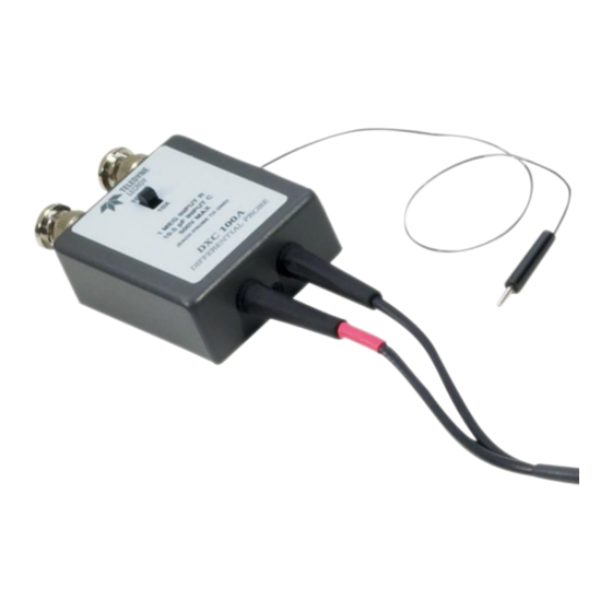
- Page 1 Operator’s Manual DXC100A Differential Probe Pair...
-
Page 3: Warranty
Spare parts, replacement parts and repairs are warranted for 90 days. In exercising its warranty, Teledyne LeCroy, at its option, will either repair or replace any assembly returned within its warranty period to the Customer Service Department or an authorized service center. -
Page 4: Safety Instructions
DXC100A Differential Probe Pair Safety Instructions This section contains instructions that must be observed to keep this oscilloscope accessory operating in a correct and safe condition. You are required to follow generally accepted safety procedures in addition to the precautions specified in this section. The overall safety of any system incorporating this accessory is the responsibility of the assembler of the system. -
Page 5: Operating Environment
Precision Voltage Generator (PVG) display. Although primarily designed for use with Teledyne LeCroy amplifiers, the DXC100A can be used with any oscilloscope or plug-in unit with an input impedance of 1 MΩ/15-26pF and one inch (25.4 mm) spacing between connectors. - Page 6 DXC100A Differential Probe Pair A Word about Differential Amplifiers and Probes When using a differential amplifier it is very important to understand the role probes play in the overall measurement system performance. Probes not only make attachment to the circuit under test more convenient, 10X and 100X attenuating probes also extend the common mode range of the differential amplifier.
-
Page 7: Probe Grounding
Operator’s Manual Probe Grounding The DXC100A Probe Pair is supplied with accessories allowing for three probe ground connection methods. In most cases, when the common mode portion of the signal consists mainly of low frequencies (1 MHz and below), the probe ground leads should not be connected to the ground of the circuit under test. - Page 8 (e.g., 155 volts with 10X and DA1855A ATTENUATOR set to X1). 2. Set the DXC100A to 10X. Adjust C8 (-X10 LF) so as to minimize the total deflection. 3. Set the DXC100A to 100X. Adjust C18 (-X100 LF1) so as to minimize the total deflection.
-
Page 9: Full Calibration Procedure
Trimmer Tool Not supplied with probes Refer to Figure 1, The DXC100A Board Layout for the location of adjustments, and to the schematic diagram in Figure 2, The DXC100A Schematic for guidance. Both figures can be found at the end of this manual. - Page 10 10X to 100X. IMPORTANT NOTES ABOUT THIS STEP: The DXC100A provides probe attenuation factor information to the DA1855A through an 11” black wire which should be plugged into the DA1855A Probe Coding Input jack on the DA1855A rear panel. If the...
- Page 11 BNC T (two female BNC and one male BNC connected together without any matching resistors). With the DXC100A connected, let 20 minutes pass to allow the DA1855A to warm up before performing the calibration procedure. 2. +Input X10 DC Attenuation a.
- Page 12 DXC100A Differential Probe Pair b. Adjust R6 (-X10 DC) to bring the DA1855A output to center screen (0 volts) on the oscilloscope. This is a very critical adjustment, and it is desirable to disconnect both probes from the source simultaneously (by removing the BNC T) and observe that the trace stays within 0.25 div...
- Page 13 Operator’s Manual 6. +Input X10 LF Compensation NOTE: Low frequency compensation of the DXC100A probe attached to the +Input is done by observing a small portion of the large amplitude step. With this magnification, the waveform shows considerable deviation from flat. What is important is that the front (1μs) and rear (about 10ms) of the waveform are at...
- Page 14 DXC100A Differential Probe Pair 8. +Input X10 HF Transient Response a. Press the –Input Off button. b. Set the BW Limit to Full. c. Press the X1 Gain button. d. Set the oscilloscope to 20mV/div. e. Connect the +probe to the pulse generator’s fast rise output using a 50 Ohm termination and the BNC to probe tip adaptor.
- Page 15 Operator’s Manual 10. +Input X100 LF Compensation NOTE: Low frequency compensation of the DXC100A probe attached to the +Input is done by observing a small portion of a large amplitude step. For the 100X probe attenuation, the oscilloscope transient response plays an important part in determining the correct LF compensation adjustment.
- Page 16 DXC100A Differential Probe Pair 11. X100 LF CMRR a. Continuing from the previous step, disconnect the probe from the pulse generator. b. Connect both probes to the pulse generator’s high amplitude output using a 50 Ohm or (preferably) 75 Ohm termination, the BNC T, and two BNC to probe tip adapters.
- Page 17 C8 (–X10 LF), R2 (-X10 HF1), R8 (-X10 HF2) or C18 (–X100 LF1), and R18 (-X100 HF1) as needed. This is the same as performing the DXC100A Probe Short Calibration Procedure.
- Page 18 CMRR adjustments made to the probe in the future should be done to the – probe. At this point, do not change any of the +Input X10 or +Input X100 Adjustments, as doing so may require repeating the entire probe calibration procedure. Figure 1, The DXC100A Board Layout 922259-00 Rev A...
- Page 19 Operator’s Manual Figure 2, The DXC100A Schematic 922259-00 Rev A...
-
Page 20: Emc Compliance
DXC100A Differential Probe Pair Certifications This section contains the instrument’s Electromagnetic Compatibility (EMC), Safety and Environmental certifications. EMC Compliance EC Declaration of Conformity - EMC The probe meets intent of EC Directive 2004/108/EC for Electromagnetic Compatibility. Compliance was demonstrated to the following specifications as... -
Page 21: Safety Compliance
The instrument is subject to disposal and recycling regulations that vary by country and region. Many countries prohibit the disposal of waste electronic equipment in standard waste receptacles. For more information about proper disposal and recycling of your Teledyne LeCroy product, please visit teledynelecroy.com/recycle. Restriction of Hazardous Substances (RoHS) -
Page 22: Contact Teledyne Lecroy
DXC100A Differential Probe Pair Contact Teledyne LeCroy Teledyne LeCroy Service Centers United States and Canada - United States - Protocol Solutions Group World Wide Corporate Office Teledyne LeCroy Corporation Teledyne LeCroy Corporation 3385 Scott Boulevard 700 Chestnut Ridge Road Santa Clara, CA, 95054, USA...
Need help?
Do you have a question about the DXC100A and is the answer not in the manual?
Questions and answers