Table of Contents
Advertisement
Quick Links
Download this manual
See also:
Operator's Manual
Advertisement
Table of Contents

Related Manuals for Teledyne Lecroy HVD3000


Summary of Contents for Teledyne Lecroy HVD3000
- Page 1 Operator’s Manual HVD3000 / HVD3000A High-Voltage Differential Probes 1.800.561.8187 information@itm.com www. .com...
-
Page 2: Table Of Contents
Required Equipment ......................... 23 Preliminary Procedure......................24 Certification Procedure ......................24 Checking Probe Attenuation in XStreamBrowser ..............26 HVD3000 / HVD3000A Test Record ..................27 Operation ............................28 Connecting to the Test Instrument ..................28 Connecting to the Test Circuit ....................28 Operating with an Oscilloscope .................... - Page 3 The product is warranted for normal use and operation, within specifications, for a period of one year from shipment. Teledyne LeCroy will either repair or, at our option, replace any product returned to one of our authorized service centers within this period. However, in...
-
Page 4: Introduction
Operator’s Manual Introduction The HVD3000 and HVD3000A high-voltage active differential probes are safe, easy-to-use, and ideally suited for power electronics applications where the reference potential is elevated from ground. The probes feature: Differential voltage measurement capability in high common-mode environments •... - Page 5 Compatibility HVD3000 and HVD3000A probes are compatible with most Teledyne LeCroy MAUI oscilloscopes equipped with the ProBus interface. See the HVD3000 product page on our website for all compatible oscilloscope models. Some legacy oscilloscopes, such as WavePro 7000A and WaveSurfer XS, can be made compatible with HVD3000 probes if upgraded to the Windows XP Professional operating system and requisite firmware.
-
Page 6: Safety
Operator’s Manual Safety To maintain the probe in a correct and safe condition, observe generally accepted safety procedures in addition to the precautions specified in this section. The overall safety of any system incorporating this product is the responsibility of the assembler of the system. Symbols These symbols appear on the probe and accessories or in this manual to alert you to important safety considerations. - Page 7 HVD3000 / HVD3000A High-Voltage Differential Probes Keep fingers behind the finger guard of the probe accessories. Do not remove the probe's casing. Touching exposed connections may result in electric shock or burn. CAUTION. To prevent damage to the equipment: Use only as specified. The probe is intended to be used only with compatible Teledyne LeCroy instruments.
-
Page 8: Voltage Derating For Accessories
Operator’s Manual Voltage Derating for Accessories Derated Max. Input Voltage for Accessory Part Number Combined Probe & Accessory (either input to ground)* Spade Terminals PK-HVA-05 1000 V CAT III Safety Alligator Clips PK-HVA-01 1000 V CAT III Plunger Alligator Clips PK-HVA-04 1000 V CAT III Plunger Pincer Clips... -
Page 9: Hvd310X And Hvd310Xa Probes
HVD3000 / HVD3000A High-Voltage Differential Probes HVD310x and HVD310xA Probes Probe Kit The probes are delivered with the following: Item Description Safety Rating* Part Number Spade Designed to connect to terminal Insulated 1000 V CAT III PK-HVA-05 Terminals strips, posts and screws, the overall length is 63 mm (2.48 inches). - Page 10 Operator’s Manual Item Description Safety Rating* Part Number Plunger The clip is designed to securely Insulated 1000 V CAT III PK-HVA-04 Alligator grasp thick wires, cables, ground Clips leads, rails, and screw heads. The overall length is 153 mm (6.02 inches);...
- Page 11 HVD3000 / HVD3000A High-Voltage Differential Probes HVD310x / HVD310xA Specifications For the current specifications, see the product datasheet a Below are some key product specifications. Specifications are subject to change without notice. UARANTEED PECIFICATIONS HVD3102/ HVD3106/ HVD3106-6M/ HVD3102A HVD3106A HVD3106A-6M...
- Page 12 Operator’s Manual HVD310x / HVD310xA Bandwidth HVD3102 / HVD3102A T YPICAL ANDWIDTH HVD3106 / HVD3106A T YPICAL ANDWIDTH 1.800.561.8187 information@itm.com www. .com...
- Page 13 HVD3000 / HVD3000A High-Voltage Differential Probes HVD3106-6M / HVD3106A-6M T YPICAL ANDWIDTH 1.800.561.8187 information@itm.com www. .com...
- Page 14 Operator’s Manual HVD310x / HVD310xA Common Mode Rejection Ratio HVD3102 / HVD3102A T CMRR P YPICAL ERFORMANCE HVD3106 / HVD3102A T CMRR P YPICAL ERFORMANCE 1.800.561.8187 information@itm.com www. .com...
- Page 15 HVD3000 / HVD3000A High-Voltage Differential Probes HVD310x / HVD310xA Voltage Derating and Burn Limit The Maximum Input Voltage curve (solid line) shows the maximum voltage that can be applied to the probe inputs without risking damage to the probe. The lower Burn Limit curve (dashed line) shows the maximum voltage that can be applied to the probe inputs while the operator is handling the inputs.
-
Page 16: Hvd3206 And Hvd3206A Probes
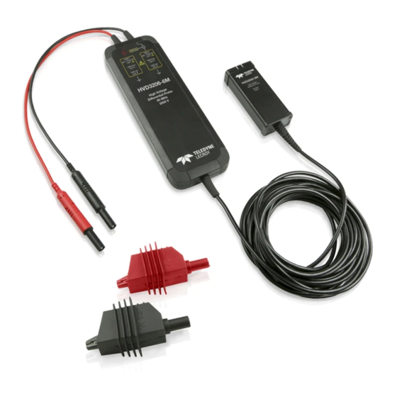
Operator’s Manual HVD3206 and HVD3206A Probes Probe Kit The probes are delivered with the following: Part Number ‡ Item Description Safety Rating* 2kV Plunger The clip is designed to securely grasp 2000 V (DC+Peak AC) CAT I** PK-HVA-07 Alligator thick wires, cables, ground leads, rails, 1000 Vrms CAT III Clips and screw heads. - Page 17 HVD3000 / HVD3000A High-Voltage Differential Probes HVD3206 / HVD3206A Specifications For the current specifications, see the product datasheet at Below are some key product specifications. Specifications are subject to change without notice. UARANTEED PECIFICATIONS HVD3206/ HVD3206-6M/ HVD3206A HVD3206A-6M Bandwidth (probe only)
- Page 18 Operator’s Manual HVD3206 / HVD3206A Bandwidth HVD3206 / HVD3206A T YPICAL ANDWIDTH HVD3206-6M / HVD3206A-6M T YPICAL ANDWIDTH 1.800.561.8187 information@itm.com www. .com...
- Page 19 HVD3000 / HVD3000A High-Voltage Differential Probes HVD3206 / HVD3206A Common Mode Rejection Ratio CMRR P YPICAL ERFORMANCE 1.800.561.8187 information@itm.com www. .com...
- Page 20 Operator’s Manual HVD3206 / HVD3206A Voltage Derating and Burn Limit The Maximum Input Voltage curve (solid line) shows the maximum voltage that can be applied to the probe inputs without risking damage to the probe. The lower Burn Limit curve (dashed line) shows the maximum voltage that can be applied to the probe inputs while the operator is handling the inputs.
-
Page 21: Hvd3605 And Hvd3605A Probes
HVD3000 / HVD3000A High-Voltage Differential Probes HVD3605 and HVD3605A Probes Probe Kit The probes are delivered with the following: Part Number ‡ Item Description Safety Rating* 6kV Alligator Designed to reliably grip large 6000 V CAT I** PK-HVA-06 Clips components, such as bus bars and... - Page 22 Operator’s Manual HVD3605 / HVD3605A Specifications For the current specifications, see the product datasheet at Below are some key product specifications. Specifications are subject to change without notice. UARANTEED PECIFICATIONS HVD3605/ HVD3605A Bandwidth (probe only) 100 MHz Risetime 10-90% 4.3 ns 80 db @ 50 Hz CMRR Test Limits, 23 C 60 db @ 10 KHz...
- Page 23 HVD3000 / HVD3000A High-Voltage Differential Probes HVD3605 / HVD3605A Bandwidth YPICAL ANDWIDTH HVD3605 / HVD3605A Common Mode Rejection Ratio CMRR P YPICAL ERFORMANCE 1.800.561.8187 information@itm.com www. .com...
- Page 24 Operator’s Manual HVD3605 / HVD3605A Voltage Derating and Burn Limit The Maximum Input Voltage curve (solid line) shows the maximum voltage that can be applied to the probe inputs without risking damage to the probe. The lower Burn Limit curve (dashed line) shows the maximum voltage that can be applied to the probe inputs while the operator is handling the inputs.
-
Page 25: Functional Test Procedure
HVD3000 / HVD3000A High-Voltage Differential Probes Functional Test Procedure This procedure should be performed to confirm the basic operation of an HVD3000 or HVD3000A probe or to aid in determining the source of a problem rather than to verify the accuracy of the probe. -
Page 26: Performance Verification Procedure
Operator’s Manual Performance Verification Procedure This procedure can be used to verify the warranted characteristics of an HVD3000 or HVD3000A probe. If the product does not meet specifications, it should be returned to a . A s there are no user accessible adjustments, there is no adjustment procedure. -
Page 27: Preliminary Procedure
HVD3000 / HVD3000A High-Voltage Differential Probes Preliminary Procedure 1. Connect the probe under test to the female end of the ProBus Extension Cable. Connect the male end of the ProBus Extension Cable to channel 1 (C1) of the oscilloscope. 2. Turn on the oscilloscope and allow at least 30 minutes warm-up time before performing the Certification Procedure. - Page 28 Operator’s Manual 9. Using the insulated banana couplers, connect the positive lead (red) of the probe under test to the positive output of the BNC-to-banana plug adapter and the negative lead (black) to the negative or return output. 10. Set the oscilloscope scale factor to: 20 V/Div for HVD310x, HVD310xA, HVD3206, and HVD3206A •...
-
Page 29: Checking Probe Attenuation In Xstreambrowser
HVD3000 / HVD3000A High-Voltage Differential Probes Checking Probe Attenuation in XStreamBrowser Probe attenuation and other values can be found by using the XStreamBrowser application that is installed with the oscilloscope firmware. 1. Choose File > Minimize to show the oscilloscope desktop, then double-click the XStreamBrowser icon. -
Page 30: Hvd3000 / Hvd3000A Test Record
Operator’s Manual HVD3000 / HVD3000A Test Record Serial Number:____________________________________________________ Asset / Tracking Number: _________________________________________ Date:______________________________________________________________ Technician:________________________________________________________ Equipment Model Serial Number Calibration Due Date Oscilloscope Digital Multimeter Function Generator* * In this Performance Verification Procedure, the function generator is used for making relative measurements. The output of the generator is measured with a DMM or oscilloscope. -
Page 31: Operation
NOTE: For accurate measurements, connect the probe to the oscilloscope and allow it to warm up for at least 20 minutes. When using HVD3000 probes, perform Auto Zero prior to connecting probe leads to the DUT. HVD3000A probes may be connected to the DUT during Auto Zero. -
Page 32: Operating With An Oscilloscope
Operating with an Oscilloscope When the probe is connected to a Teledyne LeCroy oscilloscope, the displayed scale factor and measurement values will be adjusted to account for the effective gain of the probe. - Page 33 HVD3000 / HVD3000A High-Voltage Differential Probes Offset Offset allows you to remove a DC bias voltage from the differential input signal while maintaining DC coupling. This ensures that the probe will never be overdriven while a signal is displayed on screen and prevents inaccurate measurements.
- Page 34 Operator’s Manual AC Coupling In general, using offset to adjust a differential DC voltage on the screen is the preferred method to measure transient signals in the presence of a larger DC voltage. The offset has limits that will cause a signal that is beyond the linear operating range of the probe to go off the screen, preventing measurement errors.
- Page 35 Auto Zero is invoked manually from the Probe dialog that appears behind the Channel setup dialog when the probe is connected to the oscilloscope. NOTE: When using HVD3000 probes, disconnect the probe from the test circuit before performing Auto Zero. HVD3000A probes may remain connected during Auto Zero.
-
Page 36: Maintenance
Performance Verification Procedure is included in this manual. Service Strategy HVD3000 and HVD3000A probes utilize fine-pitch surface mount devices. It is, therefore, impractical to attempt repair in the field. Defective probes must be returned to a CAUTION. Do not remove the covers. Refer all servicing to qualified personnel. A defective probe under warranty will be replaced with a factory refurbished probe. -
Page 37: Returning A Product For Service
HVD3000 / HVD3000A High-Voltage Differential Probes Reference Common Mode Rejection Ratio The ideal differential probe/amplifier would sense and amplify only the differential mode voltage component and reject the entire common mode voltage component. Real differential amplifiers are not perfect, and a small portion of the common mode voltage component appears at the output. -
Page 38: Technical Support
Operator’s Manual Differential Mode and Common Mode Differential probes sense the voltage difference that appears between the + and – inputs. This is referred to as the Differential or Normal Mode voltage. The voltage component that is referenced to earth and is identical on both inputs is rejected by the amplifier. This is referred to as the Common Mode voltage and can be expressed as: Differential Mode Range and Common Mode Range Differential Mode range is the maximum signal that can be applied between the + and -... - Page 39 HVD3000 / HVD3000A High-Voltage Differential Probes IEC/EN 61010-031 Definitions IEC/EN 61010-031/A1:2008 Measurement Category III (CAT III) applies to test and measuring circuits connected to the distribution part of the building’s low-voltage mains installation. Measurement Category II (CAT II) applies to test and measuring circuits connected directly to utilization points (socket outlets and similar points) of the low-voltage mains installation.
-
Page 40: Certifications
Operator’s Manual Certifications Teledyne LeCroy certifies compliance to the following standards as of the time of publication. As standards evolve, these certifications may no longer be current. Please see the EC Declaration of Conformity certificate shipped with your product. EMC Compliance EC Declaration of Conformity - EMC The probe meets the intent of EC Directive 2014/30/EU for Electromagnetic Compatibility. - Page 41 HVD3000 / HVD3000A High-Voltage Differential Probes Safety Compliance EC Declaration of Conformity - Low Voltage The probe meets the intent of EC Directive 2014/35/EU for Product Safety. Compliance was demonstrated to the following specifications as listed in the Official Journal of the...