Table of Contents
Advertisement
Advertisement
Table of Contents

Subscribe to Our Youtube Channel
Related Manuals for Teledyne Lecroy MDA810


Summary of Contents for Teledyne Lecroy MDA810
- Page 1 Motor Drive Analyzer Getting Started Guide...
- Page 3 However, clients are encouraged to duplicate and distribute Teledyne LeCroy documentation for internal educational purposes. HDO and Teledyne LeCroy are trademarks of Teledyne LeCroy, Inc. Windows is a registered trademark of Microsoft Corporation. Other product or brand names are trademarks or requested trademarks of their respective holders.
-
Page 4: Table Of Contents
Welcome Thank you for buying a Teledyne LeCroy product. We’re certain you’ll be pleased with the detailed features unique to our instruments. This Getting Started Guide covers important safety and installation information about your Motor Drive Analyzer, along with some basic operating procedures so you’re quickly working with waveforms. - Page 5 INTRODUCTION Motor Drive Analyzer...
-
Page 6: Introduction About The Motor Drive Analyzer
INTRODUCTION About the Motor Drive Analyzer HD4096 Technology The Motor Drive Analyzer (MDA) captures waveforms from the drive power section, power transistors, and embedded control system and performs HD4096 high-definition technology consists of high sample rate 12-bit three-phase power analysis of the power section waveforms in one high- ADCs, high signal-to-noise input amplifiers, and a low-noise system performance instrument, enabling debug and analysis of all aspects of the architecture. -
Page 7: Specifications
Specifications Materials List Detailed specifications are maintained in the Datasheet on the product Check that you have all the parts listed here. Contact Teledyne page at teledynelecroy.com. LeCroy immediately if any part is missing. • 1 Motor Drive Analyzer Key Specifications •... -
Page 8: General Safety Information
INTRODUCTION General Safety Information Precautions This section contains instructions that must be observed to keep the instrument operating in a correct and safe condition. You are required to • Use proper power cord. Use only the power cord shipped with this follow generally accepted safety procedures in addition to the precautions instrument and certified for the country of use. -
Page 9: Support
Altitudes: up to 3,000 m (at < 30° C) Manuals, tutorials, application notes, white papers, and videos are available to help you get the most out of your Teledyne LeCroy products. Power and Ground Connections The MDA/HDO8000 Operator’s Manual can be downloaded from The MDA operates from a single-phase, 100 to 240 Vrms (±... - Page 10 INTRODUCTION...
- Page 11 SET UP Motor Drive Analyzer...
-
Page 12: Set Up
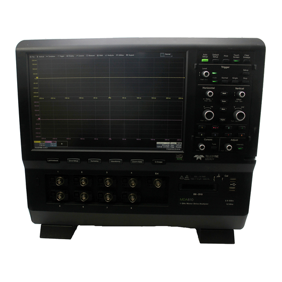
SET UP The Front of Your MDA Touch Screen Display Front Panel Shortcut Buttons launch Motor Drive Analyzer software functions (p. 28) Built-in Stylus Holder Power Button Channel Inputs Mixed Signal Interface Ground and Calibration Output Terminals USB Ports Tilting Feet... - Page 13 The touch screen display is the principal viewing and control center of the Front mounted host USB ports can Motor Drive Analyzer. See “Touch Screen Display” for an overview of its be used for transferring data or components. connecting peripherals such as a mouse or keyboard.
-
Page 14: Signal Inputs
Probes Motor Drive Analyzers are compatible with the included passive probes and all Teledyne LeCroy ProBus active probes that are rated for the instrument’s bandwidth. Probe specifications and documentation are available at teledynelecroy.com/probes. -
Page 15: The Side Of Your Mda
The Side of Your MDA The side of the MDA houses a removable hard drive. To remove the drive: Loosen the two knobs that secure the cover and remove it. You may use a screwdriver to loosen the knobs. Grab the drive by the attached tab and pull out. -
Page 16: The Back Of Your Mda
SET UP The Back of Your MDA Built-in Carrying Handle Ref In/Out connector to input/output an external Reference Clock Aux Out connector to send device trigger enabled, trigger out, or pass/ fail output to another device USBTMC Port for remote control Ethernet Ports (2) for LAN connection USB 3.0 Ports (4) DisplayPort for external monitor... -
Page 17: Powering On/Off
Powering On/Off Connecting Connect the line cord rated for your country to the AC power inlet on the After start up, configure the MDA connections as necessary. See the back of the instrument, then plug it into a grounded AC power outlet. MDA/HDO8000 Operator’s Manual for more detailed instructions. -
Page 18: Language Selection
SET UP Language Selection The MDA accepts DHCP network addressing. Connect a cable from To change the language that appears on the display, go to Utilities > either Ethernet port on the back panel to a network access device. Go to Preference Setup >... -
Page 19: Software Activation
To download and install the update: To purchase an option, contact your Teledyne LeCroy sales representative at the number listed in this guide. You will receive a license key via email that 1. - Page 20 SET UP...
- Page 21 USER INTERFACE Motor Drive Analyzer...
-
Page 22: User Interface
USER INTERFACE Touch Screen Display The entire display is a touch screen. Use your finger or the stylus to touch, double-touch, touch-and-drag, touch-and-hold (right click) and draw a selection box. Many controls that display information also work as “buttons” to access other functions. If you have a mouse installed, you can click anywhere you can touch to activate a control;... - Page 23 A menu bar of drop-down menus lets you access set up dialogs and A toolbar along the bottom of the main Channel, Math, Memory and other functions. All functionality can be accessed through either the menu Digital dialogs applies common actions so that you don’t have to leave bar or other shortcuts.
-
Page 24: Display Grid
USER INTERFACE Display Grid Multi-Grid Display Every grid is 8 Vertical divisions representing 4096 Vertical levels and 10 The grid area can contain multiple grids. Each grid still represents 4096 Horizontal divisions. The value represented by each division depends on Vertical levels. -
Page 25: Trace Descriptor Boxes
Trace Descriptor Boxes Channel (C1-C8), Zoom (Z1-Z12), Math (F1-F12), Memory (M1-M12), and Digital (Digital1-Digital4, with MSO) and other Motor Drive Analysis Software descriptor boxes appear along the bottom of the grid area when a trace is turned on. They have three main functions: Inform—trace descriptors summarize current settings for Arrange—if you drag-and-drop the descriptor box onto another grid, the that trace. -
Page 26: Entering/Selecting Data
USER INTERFACE Entering/Selecting Data Touch & Type Touch & Swipe Touching once In other cases, data Touch-and-swipe the screen in an up or down direction to scroll long lists activates a control. entry fields appear of values. You can also use scroll bars or Up/Down arrow keys to scroll lists In some cases, you’ll highlighted on the until you’ve selected the desired value. -
Page 27: Working With Traces
Working With Traces Touch & Drag The easiest way to turn on a trace is to use the front panel C1-C8, Dig(ital), Touch-and-drag traces, labels, cursors and trigger indicators to reposition Math, Zoom, and Mem(ory) buttons. A waveform appears on the grid, a new them on the grid. -
Page 28: Changing The Display
USER INTERFACE Changing the Display Extended Display If you have a second monitor connected, select Extend Grids on 2nd Monitor, To modify the touch screen display, choose Display > Display Setup from the then choose a grid style from the Extended Display pop-up menu. Both menu bar and make your selections from the Display dialog. - Page 29 Line and Intensity The front panel Intensity button sets the Adjust knob to control the trace intensity The trace style can be set to a series of separate sample Points or a setting. continuous vector Line. Grid Intensity makes the grid lines dimmer or brighter relative to the trace. When more data is available than can actually be displayed, Trace Intensity helps to visualize significant events by applying an algorithm that dims less frequently occurring samples.
-
Page 30: Front Panel
USER INTERFACE Front Panel Most of the front panel controls duplicate functionality available through the touch screen display. They are covered in more detail in the Basics section and in the MDA/HDO8000 Operator’s Manual. Below are a few useful front panel controls. - Page 31 BASICS Motor Drive Analyzer REFERENCE...
-
Page 32: Basics
BASICS Motor Drive Setup The Drive Setup shortcut button immediately below the touch screen opens the Motor Drive Analysis dialog for you to begin configuring your motor drive characteristics. The current settings for AC Input, DC Bus, Drive Output, and Mechanical sensors are summarized on this dialog. Use it to navigate to the detailed setup dialogs. -
Page 33: Numerics Table
Numerics Table Press the Numerics shortcut button to show or hide the Numerics measurement table. If you have not yet configured measurements, it will display the Numerics dialog for you to choose the voltage, current, power (real, apparent, and reactive), phase angle/power factor, efficiency, and mechanical measurements shown on the table. -
Page 34: Waveforms And Statistics
BASICS Waveforms and Statistics Touch a cell of the Numerics table to create a synthesized waveform tracking the value of that motor parameter (MP) over time. This also displays the MP statistics on the Statistics table. Up to 12 synthesized waveforms may be created in this way. Use the Waveforms shortcut button to show/hide all synthesized waveforms and statistics, or to access the Waveforms + Stats dialog for you to select and modify them. -
Page 35: Zoom And Gate
Zoom and Gate The Zoom+Gate shortcut button creates a new zoom trace of every active source waveform, including the Sync source(s), and every synthesized waveform. All zooms now can be controlled as a single, multi-zoom group by using the front panel Horizontal knobs or the touch screen controls. When using this feature, measurements shown on the Numerics and Statistics tables are gated to the number of measurement cycles shown in the zooms. -
Page 36: Q-Scape Multi-Tab Display Mode
BASICS Q-Scape Multi-Tab Display Mode The Q-Scape shortcut button puts the MDA into tabbed display mode. Continue pressing the button to cycle through the various Q-Scape display modes before returning to Normal display mode (no tabs). Also use the Q-Scape soft button on the menu bar to change the display mode. -
Page 37: Labnotebook
LabNotebook The integrated LabNotebook tool lets you build reports containing waveform images and custom annotations right on the MDA. You create individual Notebook Entries as you work (as simple as pressing the Print button), which are saved to a Notebook in a resident database. When you press the LabNotebook shortcut button, the LabNotebook dialog opens showing all your Notebooks and Notebook Entries, where they can be further annotated and exported into different report formats. -
Page 38: Vertical
BASICS Vertical These controls adjust the channel trace along the Y axis. From the Front Panel Analog Traces From the Display Choose Vertical > Channel Setup. Check boxes to turn on traces. Press Channel (number) button to turn on analog trace Touch any Vertical setting to change the value. - Page 39 Digital Traces From the Display Choose Vertical > Digital Setup. Choose a standard Logic Family, or enter custom values for Threshold and Hysteresis. Separate controls allow you to set different values for each bank. Touch Digital tab to choose group (1-4). Choose Display Mode of digital lines, bus trace or both.
-
Page 40: Horizontal (Timebase)
BASICS Horizontal (Timebase) These controls adjust the trace along the X axis. From the Front Panel From the Display Touch the Timebase descriptor box to open the Timebase dialog. Turn to raise or lower trigger Delay. Push to return Delay to zero. Turn to raise or lower Horizontal Scale (Time/div). -
Page 41: History Mode
History Mode History Mode allows you to review any acquisition saved in the MDA’s history buffer, which automatically stores all acquisition records until full. Not only can individual acquisitions be restored to the grid, you can “scroll” backward and forward through the history at varying speeds to capture details and changes in the waveforms over time. -
Page 42: Triggers
BASICS Triggers From the Display Touch Trigger descriptor box to open the Trigger dialog. Triggers tell the oscilloscope when to perform an acquisition. Available trigger types are described at more length in the MDA/HDO8000 Operator’s Manual. From the Front Panel Touch to choose trigger Type. -
Page 43: Cursors
Cursors From the Display Cursors set measurement points on a trace. There are five preset cursor types, each with a unique appearance on the display: Horizontal (Time), Horizontal + Vertical, Vertical (Amplitude), Horizontal (Frequency), and Horizontal (Event). These are described in more detail in the MDA/ HDO8000 Operator’s Manual. -
Page 44: Measurements & Statistics
BASICS Measurements & Statistics Measurements are waveform parameters that can be expressed as numerical values, such as amplitude or frequency (Note: these are different than the motor drive measurements). You can set up to 12 simultaneous measurements on one or more traces and view the active readout in a table. Statistical measurements can be added to the readout, along with histicons, a miniature histogram of the statistical distribution. -
Page 45: Math
Math Math traces display the result of applying a mathematical function (e.g., FFT) to one or more traces. One important distinction between math functions and measurement parameters is that the result of math is always another waveform trace, whereas the result of measurement is a number. Choose Math >... -
Page 46: Zoom
BASICS Zoom From the Display Zooms display a magnification of another trace. You can create up to 12 zooms (Z1-Z12) from any other type of trace. Draw a zoom box on a portion of a trace, then choose a zoom location (Zx). From the Front Panel Repeat on another section to open a new zoom trace. -
Page 47: Memories (Reference Waveforms)
Memories (Reference Waveforms) Memories are traces stored for reference. They can be recalled to the display for comparison with other traces. A memory can be zoomed or measured for better analysis of historical data. You can store up to 12 internal memories (M1-M12). -
Page 48: Spectrum Analyzer
BASICS Spectrum Analyzer Spectrum Analyzer lets you quickly and easily use the Fast Fourier Transform (FFT) for frequency analysis. The controls are the same as you would find on an RF spectrum analyzer. You set the inputs and desired frequency span, and the instrument automatically generates output in units relevant to the frequency domain. -
Page 49: Wavescan
WaveScan WaveScan® Search and Find enables you to search for unusual events in a single capture, or to scan for a particular event in many acquisitions over a long period of time. A predefined set of scan modes (similar to trigger setups), easily customized, enable a quick search for events of interest. The results are time stamped, tabulated, and can be selected for individual viewing. -
Page 50: Serial Decode
BASICS Serial Decode Optional serial data decoders apply software algorithms to extract encoded serial data information from physical layer waveforms measured on the instrument. The extracted information is displayed over the waveforms, color-coded to provide fast, intuitive understanding of the relationship between message frames and time synchronous events. -
Page 51: Sharing Data
Sharing Data Temperature Dependent Calibration Print/Screen Capture The MDA is calibrated at the factory prior to being shipped. This calibration is run at 23° C (± 2° C) and is valid for temperatures ± 5° C The MDA offers several ways to preserve and share data, any of which of the original calibration temperature. -
Page 52: Software Options
BASICS Software Options Part Number Description Optional software packages are available to enhance the capabilities of a Motor HDO8K-1553 TD MIL-STD-1553 Trigger and Decoder Drive Analyzer. HDO8K-ARINC429bus Dsymbolic ARINC-429 Symbolic Decoder HDO8K-Audiobus TD/TDG Audiobus Trigger and Decoder for I S, LJ, RJ Advanced Customization Package (HDO8K-XDEV) supports creation of user- and TDM (optional Graph) defined measurement parameters and math functions. - Page 53 BASICS REFERENCE Motor Drive Analyzer...
-
Page 54: Reference
REFERENCE Service 6. If returning a product to a different country: Contact your local Teledyne LeCroy service center for calibration or other service. • Mark the shipment as a Return of US manufactured goods for warranty repair/recalibration. Returning a Product •... - Page 55 Teledyne LeCroy Service Centers For a complete list of Teledyne LeCroy offices by country, including our sales and distribution partners, visit: teledynelecroy.com/support/contact World Wide Corporate Office US Protocol Solutions Group Europe Teledyne LeCroy Teledyne LeCroy Teledyne LeCroy SA 700 Chestnut Ridge Road 3385 Scott Boulevard 4, Rue Moïse Marcinhes...
- Page 56 EN61000-4-11. Electromagnetic Emissions: European Contact:* EN 55011:2010, Radiated and Conducted Emissions Group 1, Class A Teledyne LeCroy Europe GmbH EN 61000-3-2/A2:2009 Harmonic Current Emissions, Class A Im Breitspiel 11c D-69126 Heidelberg EN 61000-3-3:2008 Voltage Fluctuations and Flickers, Pst = 1...
- Page 57 For more information about proper disposal and recycling of your • Measuring Terminals: No rated measurement category. Terminals not Teledyne LeCroy product, please visit teledynelecroy.com/recycle. intended to be connected directly to the mains supply. RESTRICTION OF HAZARDOUS SUBSTANCES (RoHS) •...
- Page 58 The instrument is warranted for normal use and operation, within system. Teledyne LeCroy’s agreement with Microsoft prohibits users from specifications, for a period of three years from shipment. Teledyne LeCroy installing third-party software on MDAs that is not relevant to measuring, will either repair or, at our option, replace any product returned to one of analyzing, or documenting waveforms.
- Page 60 926061-00 October, 2015 © 2015 Teledyne LeCroy, Inc. All rights reserved.
Need help?
Do you have a question about the MDA810 and is the answer not in the manual?
Questions and answers