
Subscribe to Our Youtube Channel
Related Manuals for Teledyne Lecroy DL03-ISO


Summary of Contents for Teledyne Lecroy DL03-ISO
- Page 1 User Manual DL-ISO High Voltage Optically Isolated Probes DL03-ISO, DL07-ISO, DL10-ISO...
- Page 2 Customers are authorized to duplicate and distribute Teledyne LeCroy documentation for internal training purposes. Teledyne LeCroy is a trademark of Teledyne LeCroy, Inc. Other product or brand names are trademarks or requested trademarks of their respective holders. Information in this publication supersedes all earlier versions.
-
Page 3: Table Of Contents
User Manual Contents Safety ..............................1 Symbols ............................1 Terms ............................... 1 General Safety Precautions ......................1 High Voltage Safety ........................2 Clearance Requirements ......................2 Laser Safety ............................ 4 Safe Operating Environment ....................... 5 Introduction ............................6 Key Features ........................... 6 Compatibility ........................... - Page 4 DL-ISO High Voltage Optically Isolated Probes Performance Verification ....................... 21 Required Test Equipment ......................21 Before You Begin ........................22 Functional Check ........................22 RMS Noise Check ........................22 Gain Accuracy Check ......................... 23 DL-ISO Performance Verification Test Record ................25 Care and Maintenance........................
-
Page 5: Safety
User Manual Safety Follow these instructions to keep the probe operating in a correct and safe condition. Observe generally accepted safety procedures in addition to the precautions specified here. The overall safety of any system incorporating this accessory is the responsibility of the system owner. Symbols These symbols appear on the probe and accessories or in this manual to alert you to important safety considerations. -
Page 6: High Voltage Safety
Do not remove the probe’s casing. Touching exposed connections may result in electric shock. Do not disassemble the probe or remove inside parts. Refer all service to Teledyne LeCroy personnel. Use only indoors within the operational environment listed. Do not use in wet or explosive atmospheres. - Page 7 User Manual Maximum safe handling limits for common mode voltages between the probe head and tips with respect to earth ground. WARNING: Maintain 1 m (~40 in) safe clearance of the probe head and tip in all directions when connected to an energized circuit. Place the oscilloscope and any equipment you need to access at least 1 m from the circuit and probe head.
-
Page 8: Laser Safety
DL-ISO High Voltage Optically Isolated Probes Laser Safety CLASS 1 LASER PRODUCT WARNING: The DL-ISO probes contain multiple lasers, exposing which may cause laser burns. Do not remove any plastic or metal covers or otherwise attempt to disassemble the probe. Using controls, adjustments or procedures other than those specified in this manual may result in exposure to hazardous levels of invisible radiation. -
Page 9: Safe Operating Environment
User Manual Safe Operating Environment Temperature, Operating, 5 °C to 40 °C Probe Head Temperature, Operating, 10 °C to 35 °C Control Module Temperature, Non-operating -20 °C to 70 °C Relative Humidity 5% to 95% RH (non-condensing) 75% RH above 30 °C 45% RH above 50 °C Altitude, Operating 3000 m (9842 ft.) maximum... -
Page 10: Introduction
• Auto Zero without disconnection • Compatibility DL-ISO probes are compatible with a wide range of Teledyne LeCroy oscilloscopes equipped with the ProBus interface. To confirm compatibility with your oscilloscope model, visit: https://teledynelecroy.com/probes/probemodel.aspx?modelid=11667&categoryid=3&mseries=537 Required Firmware Versions Correct operation of the DL-ISO probes requires that the oscilloscope be installed with MAUI ®... -
Page 11: Dl-Iso Probe System
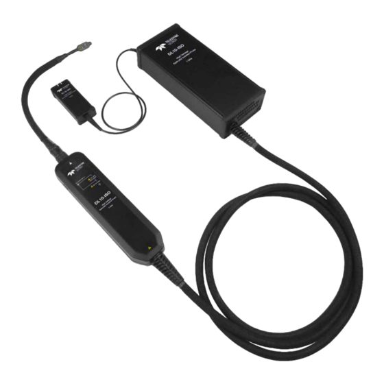
User Manual DL-ISO Probe System Standard Parts DL-ISO Probe The probe head contains a frequency modulating optical transmitter and receiver integrated with a high-performance electrical amplifier. It is connected to the control module by an integrated fiber- optic cable. The control module utilizes the ProBus interface to communicate tip attenuation value and proper voltage scaling to the oscilloscope. -
Page 12: Probe Tips (At Least One Required)
DL-ISO High Voltage Optically Isolated Probes Probe Tips (at least one required) Probe tips are sold separately from the probe itself, but at least one tip is required for proper functioning. Tips can be stored in a compartment in the soft carrying case. The 2 Vpp through 200 Vpp MMCX Tips are high-quality coaxial attenuating tips that reject unwanted noise while terminating into standard MMCX connectors. -
Page 13: Dl-Iso Probe Specifications
User Manual DL-ISO Probe Specifications For complete specifications, see the product datasheet. Specifications are subject to change without notice. Electrical Characteristics DL03-ISO DL07-ISO DL10-ISO Bandwidth 350 MHz 700 MHz 1 GHz Risetime10-90% 1.1 ns 575 ps 435 ps Input Dynamic Voltage Range... -
Page 14: Noise And Electromagnetic Compatibility (Emc)
WARNING: The probe is not intended for hand-held use. Always maintain adequate spacing between floating probe components and earth ground when measuring high voltages in a stationary test setup. Noise and Electromagnetic Compatibility (EMC) DL03-ISO DL07-ISO DL10-ISO Noise (typical) DL-ISO-2V-TIP (100 mV/div) 2.3 mVrms... -
Page 15: Tip Specifications
User Manual Tip Specifications The measurement terminals of the probe as well as all accessories are to be used only for measurements on circuits not directly connected to the mains. Use only accessories correctly rated for the Measurement Category (CAT), voltage, temperature, altitude and amperage of any measurement. -
Page 16: Bandwidth By Model
DL-ISO High Voltage Optically Isolated Probes Bandwidth by Model Typical frequency response of the DL-ISO probes when used with the DL-ISO-2V-TIP: Bandwidth by Tip Typical frequency response of the DL10-ISO probe when used with the following tips:... -
Page 17: Input Impedance Vs. Frequency
User Manual Input Impedance vs. Frequency... -
Page 18: Max. Non-Destruct Voltage (Tip Derating)
DL-ISO High Voltage Optically Isolated Probes Max. Non-destruct Voltage (tip derating) Max. Operating Voltage (tip derating) -
Page 19: Common Mode Rejection Ratio (Cmrr)
User Manual Common Mode Rejection Ratio (CMRR) CMRR varies by tip and measurement frequency. The table below shows typical values. Probe Tip 1 MHz 100 MHz 200 MHz 500 MHz 1 GHz DL-ISO-2V-TIP 160 dB 110 dB 90 dB 90 dB 80 dB 75 dB DL-ISO-10V-TIP... -
Page 20: Equivalent Circuit
DL-ISO High Voltage Optically Isolated Probes Equivalent Circuit Probe Tip DL-ISO-2V-TIP 1.2 pF 1.3 pF 0.01 pF 200 kΩ 125 Ω DL-ISO-10V-TIP 1.2 pF 0.55 pF 0.05 pF 1.0 MΩ 700 Ω DL-ISO-40V-TIP 1.6 pF 0.5 pF 1.5 pF 1.0 MΩ 3.0 kΩ... -
Page 21: Operation
User Manual Operation Note: Operating the probe requires MAUI firmware version 9.9.x.x or higher. To confirm the version, choose Utilities > Utilities Setup from the oscilloscope menu bar, then open the Status tab. Connecting the Probe to the Test Instrument Connect the probe to the oscilloscope through the ProBus input. -
Page 22: Operating With An Oscilloscope
DL-ISO High Voltage Optically Isolated Probes Operating with an Oscilloscope When the entire DL-ISO, including the attenuating tip, is connected to a Teledyne LeCroy oscilloscope, the displayed scale factor and measurement values are adjusted to account for the effective gain of the probe. The oscilloscope will set the proper probe attenuation according to the information received from the tip, while the oscilloscope probe control functions are activated, and probe gain and offset can be controlled through the oscilloscope. - Page 23 User Manual Auto Zero The Auto Zero procedure corrects for DC offset drifts that naturally occur from thermal effects in the probe system. DC offset drift is independent of probe tip connected, but it is affected by oscilloscope gain setting and ambient temperature. DL-ISO Full Scale Range (FSR) is calculated as: 8 x Vertical Gain Sensitivity For example, at 100 mV/div, FSR = 100 mV/div x 8 = 800 mV.
- Page 24 DL-ISO High Voltage Optically Isolated Probes The probe dialog will indicate when the probe has a valid calibration (green “√ Pass”): Calibrations are not cached. If the probe was previously calibrated at one temperature then re- calibrated at another before returning to the first temperature, the Precision Gain Calibration will have to be repeated.
-
Page 25: Performance Verification
User Manual Performance Verification DL-ISO probes shipped from Teledyne LeCroy are tested and adjusted to meet the Gain Accuracy specification. This procedure can be used to verify the performance of an DL-ISO. Some of the test equipment used to verify the performance may have environmental limitations required to meet the accuracy needed for the procedure. -
Page 26: Before You Begin
DL-ISO High Voltage Optically Isolated Probes Before You Begin 1. Turn on the oscilloscope and allow it to warm up for at least 20 minutes. 2. Connect the probe connector box to the oscilloscope C1 input. Verify that the C1DL-ISO tab appears behind the C1 setup dialog. -
Page 27: Gain Accuracy Check
User Manual 3. Turn on P1 and set it to measure the standard deviation (sdev) of C1. Turn on statistics. 4. Clear Sweeps, wait 10 seconds, then record the mean value shown for measurement P1:sdev(C1) on the test record and compare it to the test limit for the corresponding tip voltage and DL-ISO model number. - Page 28 DL-ISO High Voltage Optically Isolated Probes 6. Set the DMM to measure V 7. Set the oscilloscope timebase to 10 ms/div. 8. Set the function generator output to 1 MΩ termination, and the output waveform to a sine wave with a frequency of 100 Hz. 9.
-
Page 29: Dl-Iso Performance Verification Test Record
Thus, the generator is not required to be calibrated. RMS Noise Step Description Test Limit (mVrms) Test Result Probe Model Number DL03-ISO DL07-ISO DL10-ISO Mean sdev(C1) – DL-ISO-2V-TIP Mean sdev(C1) – DL-ISO-10V-TIP Mean sdev(C1) – DL-ISO-40V-TIP Mean sdev(C1) – DL-ISO-200V-TIP... -
Page 30: Care And Maintenance
Service Strategy The DL-ISO probe utilizes fine-pitch surface mount devices. Defective probes must be returned to a Teledyne LeCroy service facility for diagnosis and exchange. CAUTION: Refer all servicing to qualified personnel. A defective probe under warranty will be replaced with a factory refurbished probe. -
Page 31: Reference
3. Pack the case in its original shipping box, or an equivalent carton with adequate padding to avoid damage in transit. 4. Mark the outside of the box with the shipping address given to you by Teledyne LeCroy. Be sure to add the following: ATTN:<RMA code assigned by Teledyne LeCroy>... -
Page 32: Warranty
Teledyne LeCroy shall not be responsible for any defect, damage, or failure caused by any of the following: a) attempted repairs or installations by personnel other than Teledyne LeCroy representatives, or b) improper connection to incompatible equipment, or c) for any damage or malfunction caused by the use of non-Teledyne LeCroy supplies. -
Page 33: Certifications
European Union requirements to Directives 2012/19/EU on Waste Electrical and Electronic Equipment (WEEE). For more information about proper disposal and recycling of your Teledyne LeCroy product, visit teledynelecroy.com/recycle. Unless otherwise specified, all materials and processes are compliant with RoHS Directive... - Page 34 dl-iso-user-manual_10jun22.pdf June, 2022...
Need help?
Do you have a question about the DL03-ISO and is the answer not in the manual?
Questions and answers